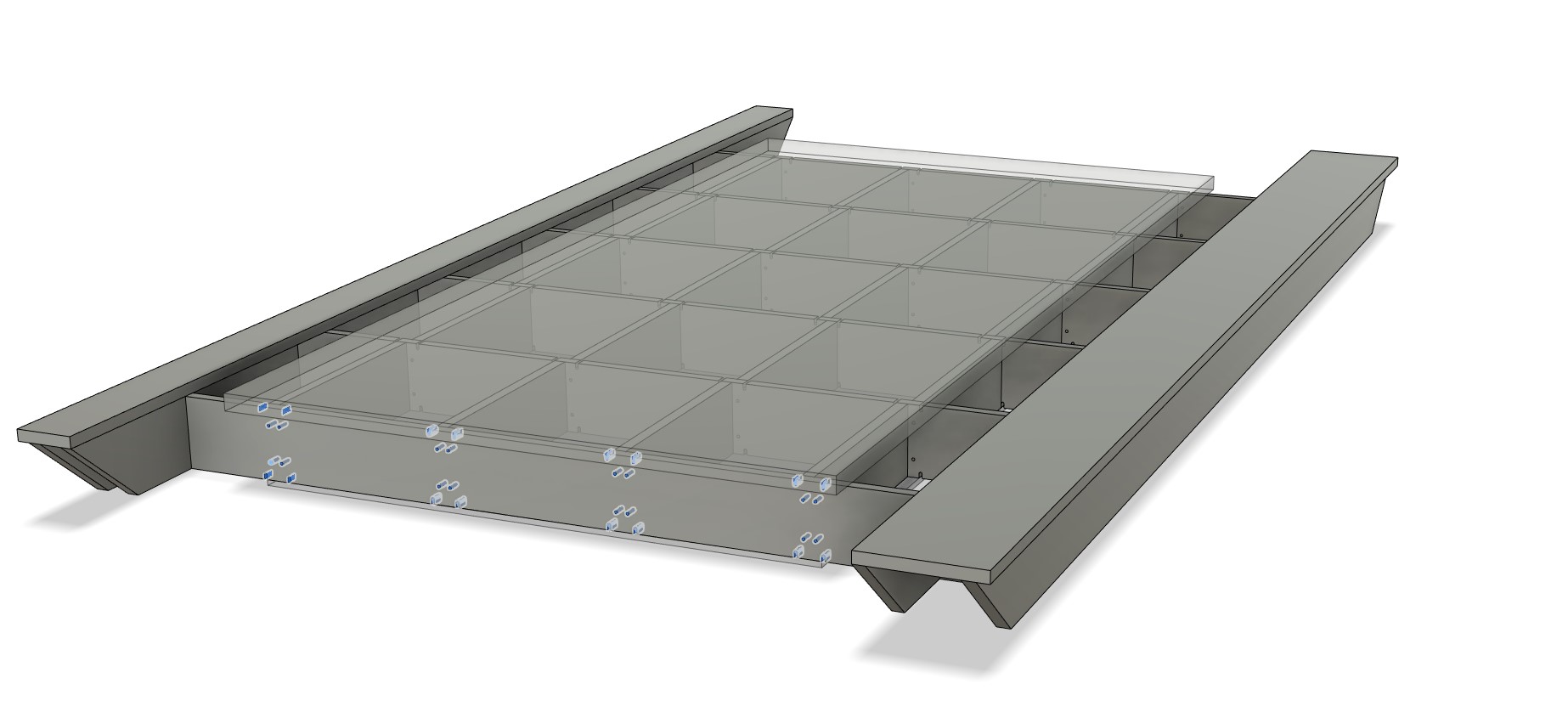
The key ideas here
*Can be cut with a CNC, table saw, or straight edge guided circular saw. Use what you have!
*If you use a CNC the alignment slots and holes can be used to speed up assembly.
*I would make the top Surface taller than the rails by at least a few mm to be able to surface it several times. If you plan carefully, you should easily be able to surface the entire thing, eliminating the swimming pool effect.
*You can skip the surfacing and make a full solid surface. This gives a nice, sturdy multi-use table.
*I need to test it but I think the rails side would be an ideal place to run the vacuum hose.
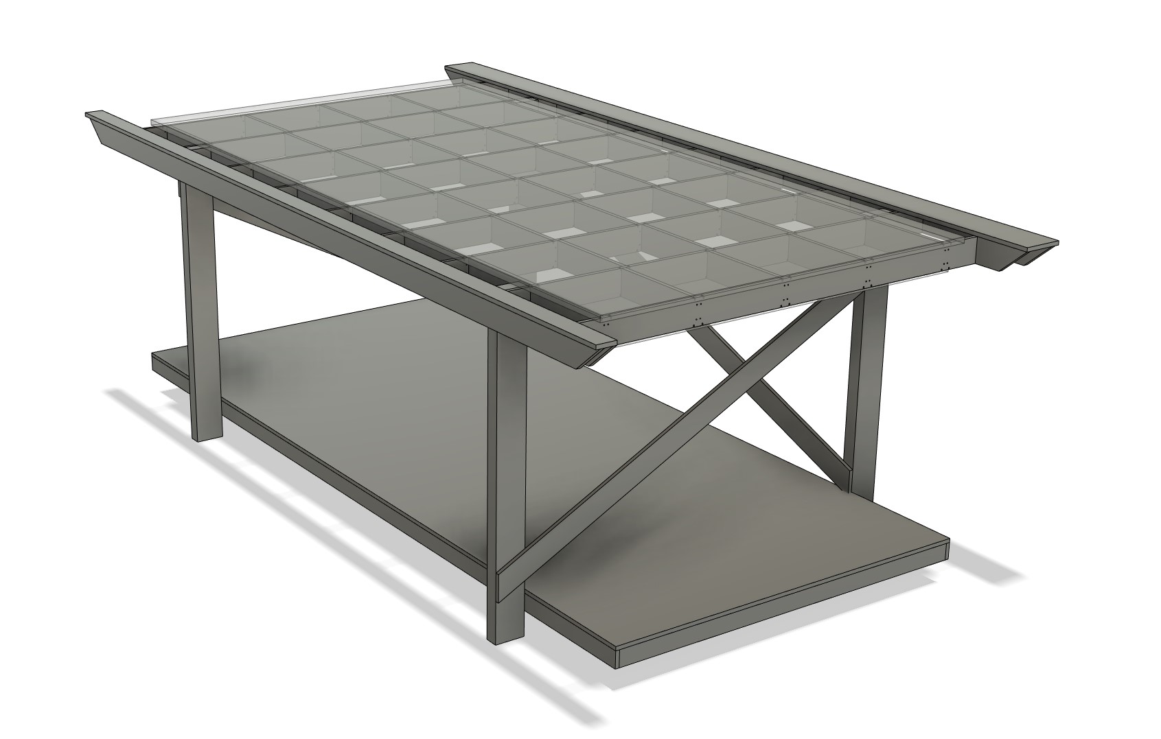
*Legs are kinda close to Bessel Points that should explain the positions depending on rib spacing. Of course, material size and use is open to interpretation and sketches and extrusions can be modified to fit your needs.
*Shelf and legs are very open to your specific use. You can use gussets instead of angled straps if you want a more open feel.
Notes-
*-Engineered wood will always be the most stable. In order of preference, MDF, Particle board, OSB, Plywood, Dimensional lumber. (in terms of stability for this specific purpose).
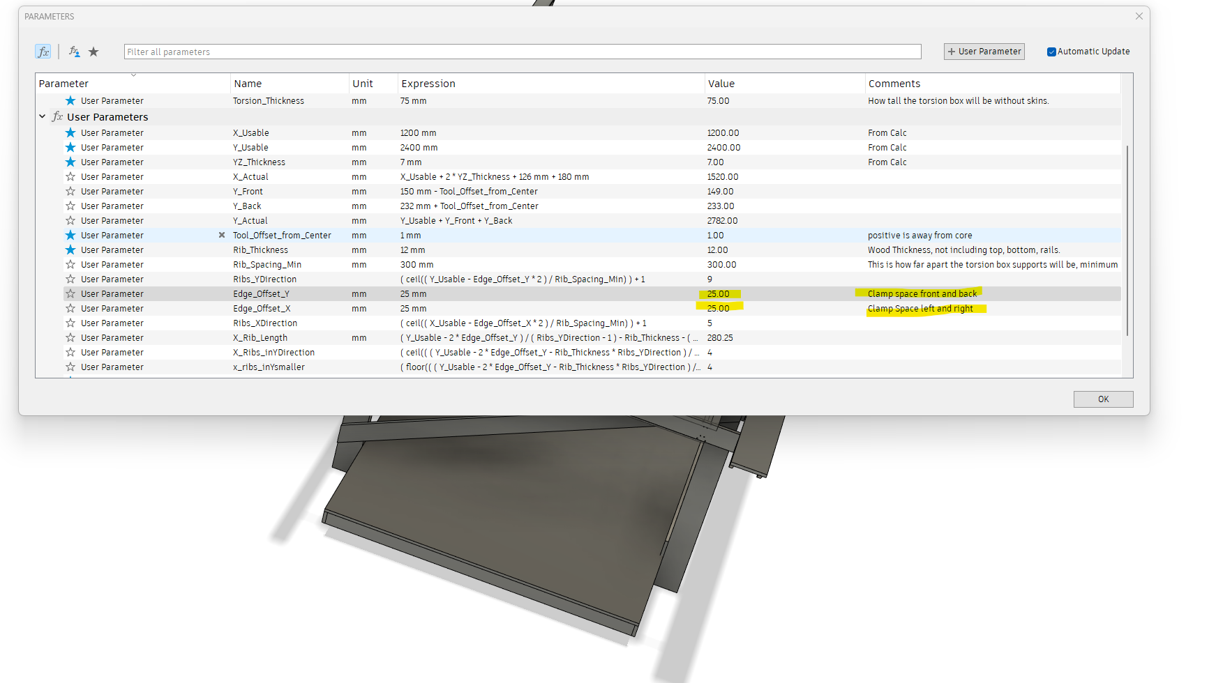
*- Front and rear area are adjustable, so if you want to make a vertical clamp just add the room you want to the numbers.
Looks awesome!
What material are the side rail “riding plates” (and their supports) cut from? I had suggested cutting them from dimensional lumber such as 1" x ?" x 10" but you had said not to use lumber.
How many sheets of plywood would this take without the shelf? Just the torsion box and side rail “riding plates”? I ask for comparison to the one I had been working on.
Oh, wait, is this not for a full sheet plus (ie. can address all of a 49x97 sheet)? I am looking at the dimensions and it seems it is not. EDIT: Sorry, it is for full size!
OK, so I guess my first question above, but related to my table, comes back into play. I had put forth an idea of doing the torsion box from plywood, but using 1"x ? x ? to get the side rail riding plates, and you had mentioned not to use lumber. MDF longer than 8’ is made, but I don’t think it’s very easy to source for many of us. Can I get you to revisit the topic, either to explain why we should not use lumber for those side rail riding plates, and/or explain what we should do instead? These would need to be about 114" long.
Engineered wood will always be the most stable. In order of preference, MDF, Particle board, OSB, Plywood, Dimensional lumber. (in terms of stability for this specific purpose).
No idea, not a concern of mine. All the parts are minimal so it can not get more efficient. If it is too much use bigger spaces between struts.
Connect two pieces. If you want to use metal or dimensional lumber it is not a big deal, connecting two pieces of wood is usually not a huge deal either. I gave you a tip, it is not a hard fast rule, I do not recommend dimensional lumber due to stability. If I remember right, you were recommending it, I just gave you a suggestion due to density and stability. I also do not recommend metal only because it is expensive. If you want to build this out of Aluminum box tube that is perfect…but beyond the philosophy of my designs.
I do everything in my power to design things for everyone in the world to be able to replicate them as inexpensive and as easily as possible for the best possible results. Every thing I design can be better with more money, better tools, exclusive or specific material or parts. I try not to lock people in.
Thanks for the ideas and input. All great points I couldn’t imagine all the things you have to considering being a world wide project.
That’s the thing that makes this so hard.
There are so many variation you can do it is damn near impossible to implement something that covers everyone’s needs.
I am so indecisive, it’s great to brain seed together.
I still like the idea of a table that you can extend. Like, pop up the rear and have double the cutting space. Would need to modify the belt tensioners that the middle ones can be taken out.
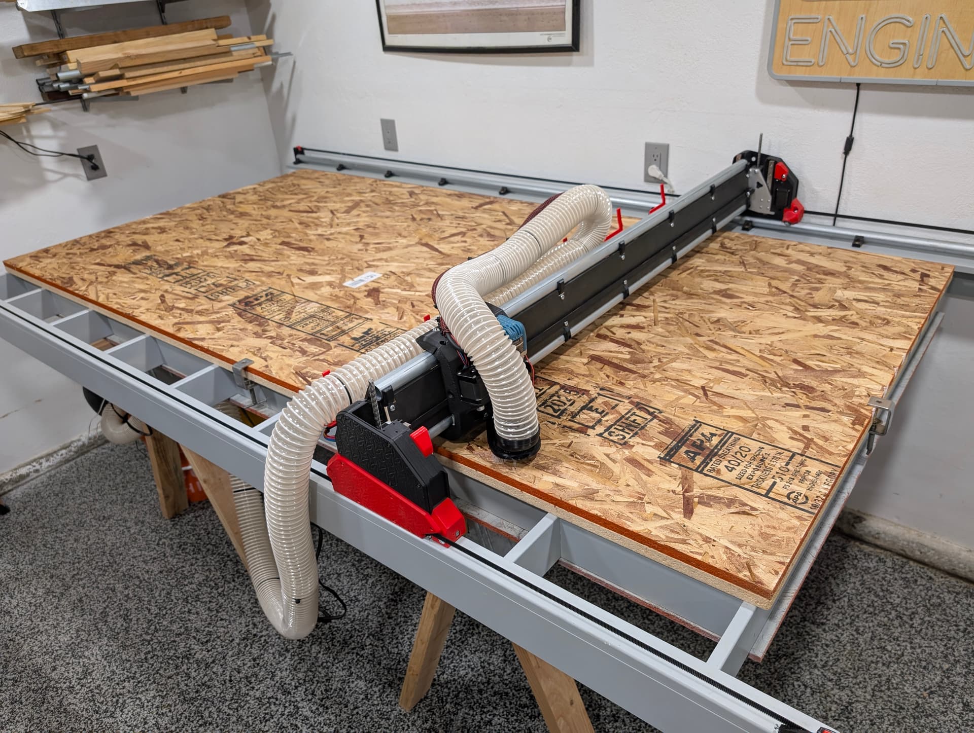
I used your design to build the table. It worked out great, easy, cheap and quick to build. It is a full sheet table. I went with 15mm mdf but i would advice others to use 18mm. It is only a small difference in price but it is easier to work with and more ridgid. A small change i would make to the design is too make the small side rail, which is now 6cm, a bit wider. The belt tension blocks for the y belt just barely fit.
Hi All, I have made a variant of this table and hoping you guys can help with where I’ve gone wrong as I’m having an issue with the router not being able to reach the end of the sheet.
My LR3 dimensions are
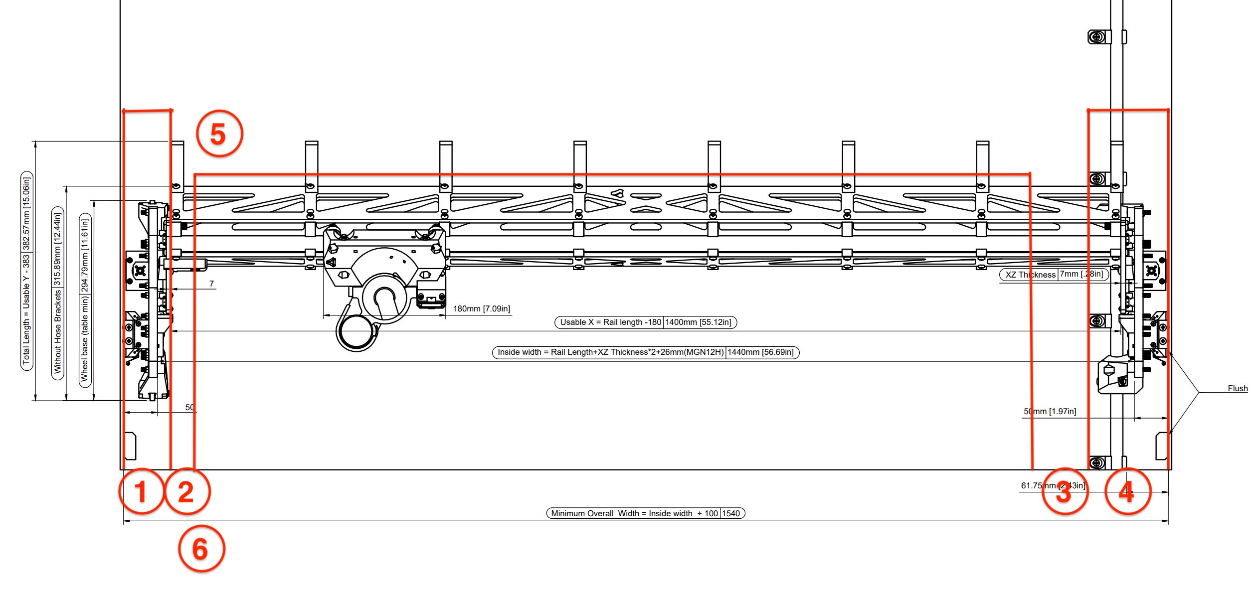
Rail length - 430mm
Cutting area - 1250x2500
Material thickness - 15mm
I used Ryans fusion model and modified the parameters to suit the required dimensions.
I then decided to change the ribs so that they would slot together, all in all from Ryans standard file with only the dimension changes vs my edits to the ribs end result all over is within a few mm. (sketches attached for ref)
Below is the original variant with only the dimension changes.
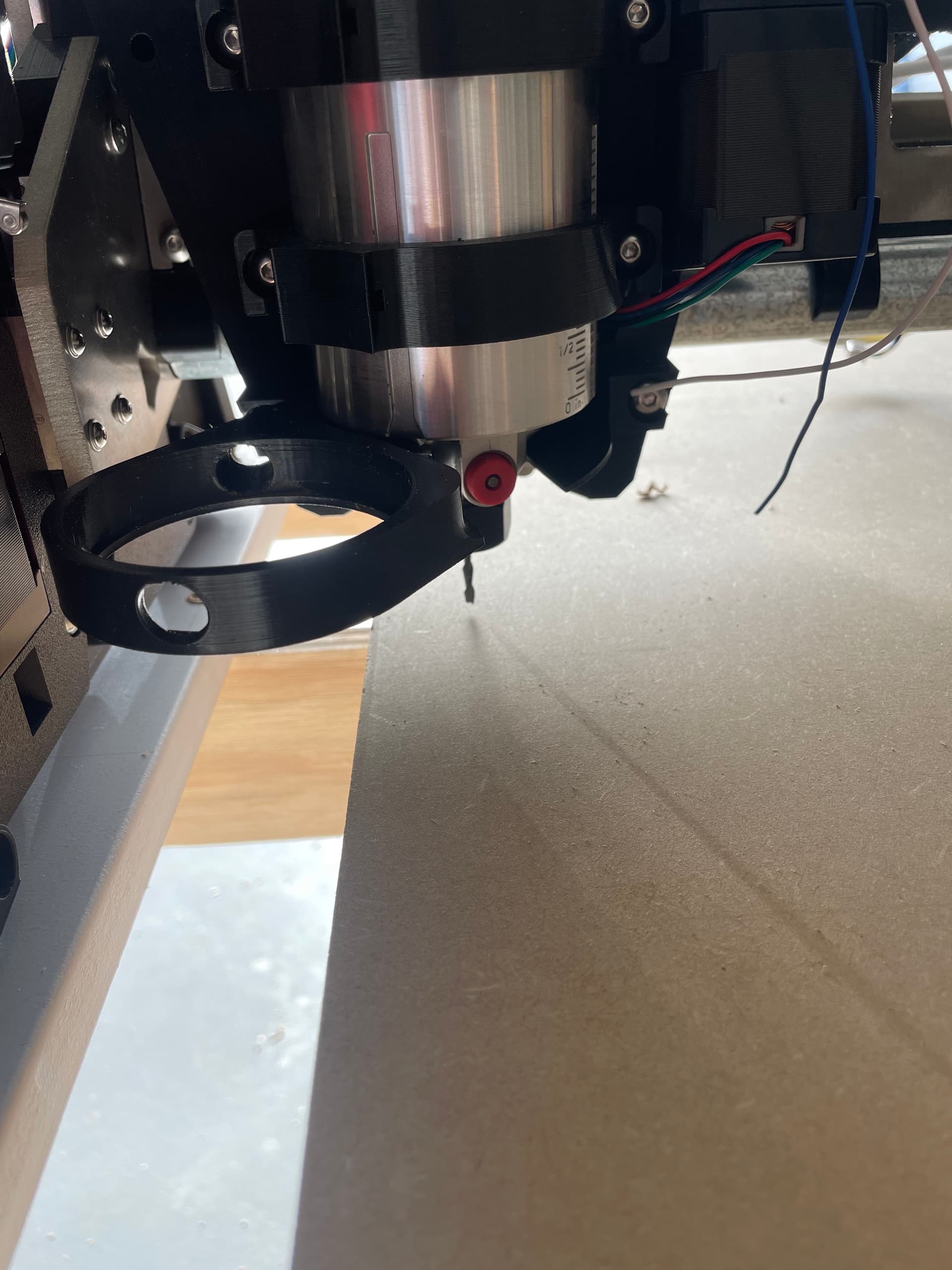
I have assembled my table and installed the rail runners with 10mm overhang as per the sketch, then installed the rail clamps at the 61.75mm in from the edge. This however puts my router 25mm in on the sheet on the X-min side when it’s touching the endstop on the X-max however it does go 35mm past the edge of the sheet.
The sides do have a parameter for an extra inch I think? You can double check but I added a clamping surface. Your bit should end at the last rib, if that is the case just cut your surface down if you do not want the clamping surface added.
I did try flip it, as I did think that could be the issue.
But if I did that the Rail and its Rail Clamps didn’t fit the Runner so assumed I had it right to begin with.
The Y-Rail is currently sitting on the side with the wider of the Y-Runners.
Your comment around the overhang makes more sense.
The bit does end at the edge of the rib on the X-min side (hope Im using the correct terminology its the side with the X-end stop)
It then travels about 60mm past the edge of the opposing rib (non X end stop side)
I set my X_Useable to 1250, from what you are saying the 25mm of clamping area on the X-min side is literally only to be used for clamping and the router bit will never reach it.
This means I only end up with a spoil board cutting area of 1225, so If I wanted to have a full width spoil board covering the entire usable X the spoil board would need to be 1275w or 1300w if I wanted it to also have the 25mm clamping area on the X-Max side.
I have also just had another play with the adjustable parameters in the fusion file and set the X clamping area to 0mm, doing this only widens the ribs themselves and doesn’t adjust the placement of the spoil board so the result is the same as the above.
That is good, you are getting 10mm extra in terms of the build calc (as expected). That means you should have been able to get 5mm off each side, or more likely a bit more on the endstop side and a bit less on the other.
Where does the endmill land on each side of your 1250mm spoil board?
Can you put up a pic of the Y rail location, that sets everything.
I am probably not alone in not particularly wanting to download F360 just to view the parameters, and I know you can’t please everyone with parametric drawings.
One of the reasons I like Onshape (and I’m not suggesting a change) is that while an account is necessary, sharing of documents does not any further software installation.
I’ll happily reproduce the drawing in Onshape if that’s of use although I tend to use an old offcut and a thumbnail dipped in tar for this sort of thing.
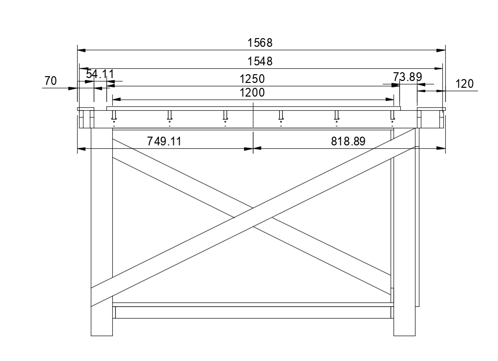
It would be very useful though if we could have the “missing” dimensions in the documents so the table can be recreated in other apps, or even manually. I know the question bobs up from time to time and it will save me doing a search!