I did some learning today, tramming

https://docs.v1e.com/mpcnc/Ptable/

This is the current table building instructions…from 2015. It has not been updated because we always end up in this cycle of…“it won’t be perfect”

Ain’t that the truth.

I like endstops, and use them regularly, because I like having repeatable stuff when something fails but is recoverable.

I’m not chasing a lot of zeros though, I trammed my Primo to be able to use a surfacing bit in it, but for the work, not for the spoilboard. I surface a small piece of scrap when I want to mill a PCB. My LR3 was adequately trammed when assembled (Though I’ve changed the router, I should check it again…)

Lasers

1 Like

Also I’ve noticed lately, well, maybe the last 5 years or so, no one want’s to read the docs. They want a youtube, or tictok, or some other bullshit other than the docs written by the $thing maintainer.

That reminds me of winding sticks. You could a white and a black stick to exaggerate the difference to make it clear. I wonder if you could even see the twist change with each 1/4 turn of the screwdriver.

Chasing zeros is neat, if you’re looking for a project. But not everyone needs an F1 racer. Some people just have a lot of fun cruising in their used subaru. And the subaru even has more room for groceries.

2 Likes

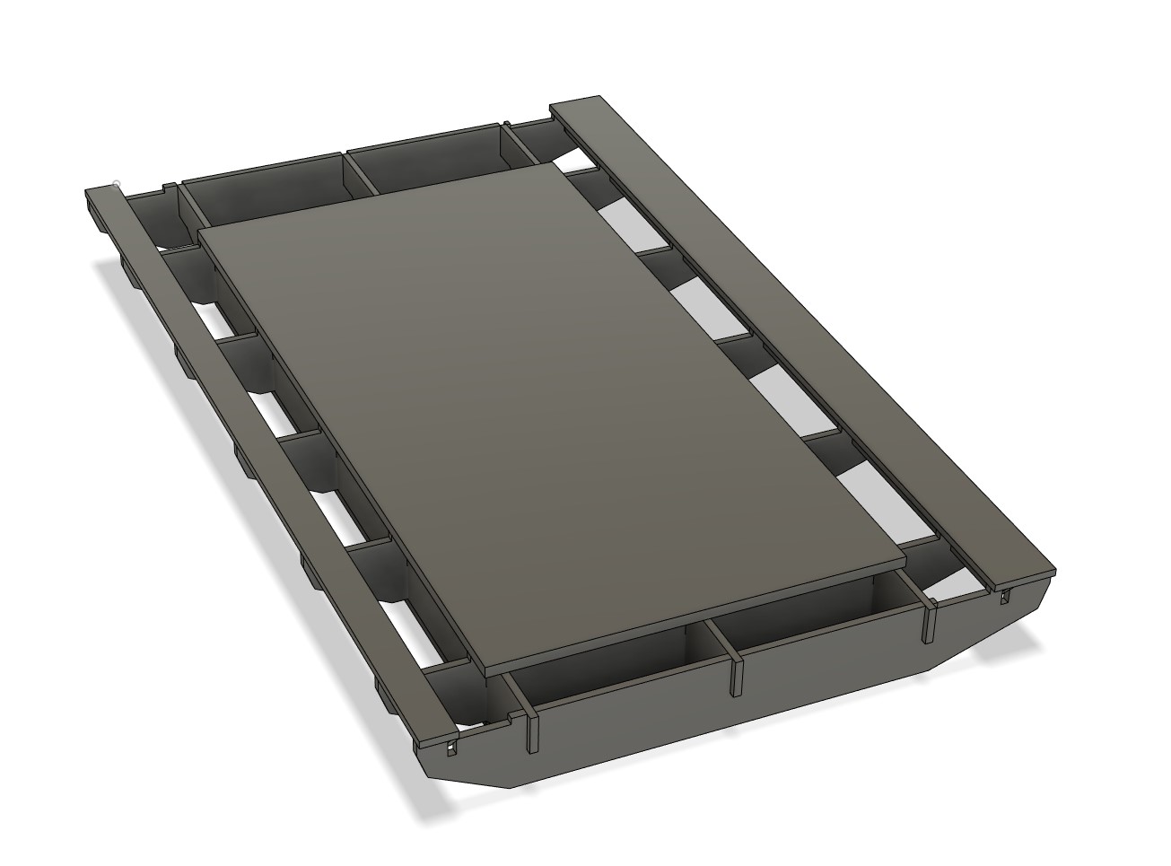
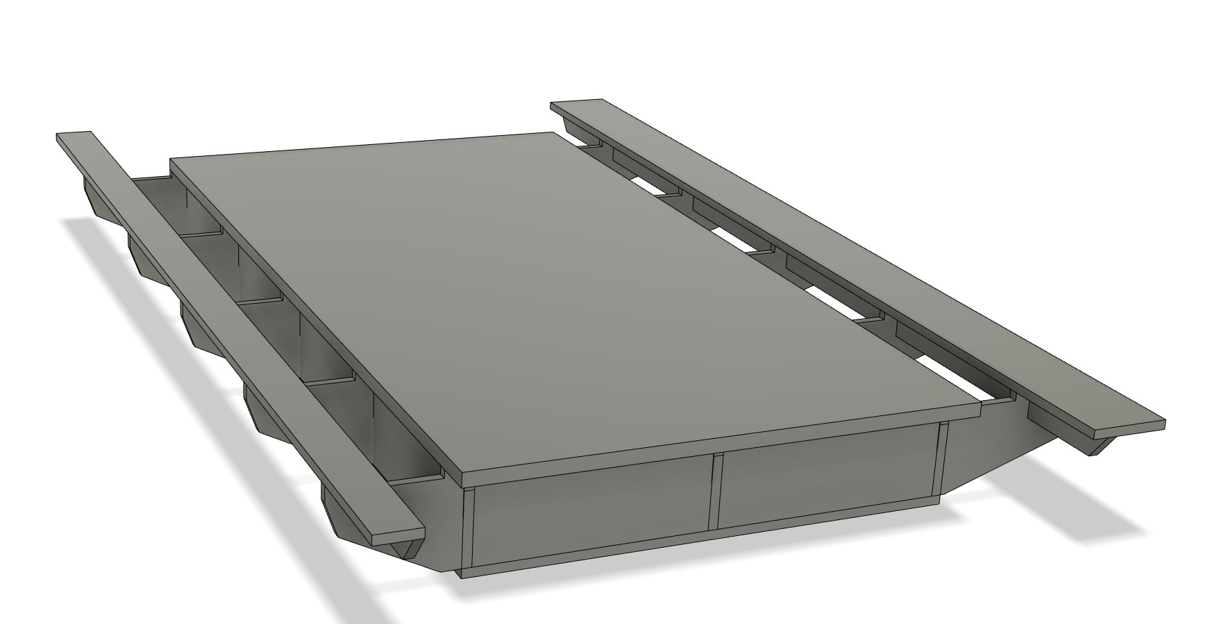
Not ready for a new thread yet. I took some sketches to basic CAD rough ideas. Not there yet.


I realized I have to focus on RMRRF, I need to bring something…time to stop farting around.


Basics are there, need to add some more mounting holes and some flavor. All the pocket holes and edge chamfers are going to test the tramming. Guess I am going to need to add in some V carves as well.

8 Likes

Are you using my pocket holes for wires past the Z axis? I did that right next to the top rail, if I were to do it again, I’d drop that to about the bottom of the motor height, I think. Still high enough to hide it, but you can get to the pockets to pass the wire through if you didn’t get it all the first time. (I had a heck of a time with the wiring for the 5V line to get to the ESP32Cam.)

I made the front (and back) panels come out to be flush with the side panels. I think it looks nicer that way. If you make the front panel and the side panels only come even with the extrusion, it doesn’t seem to look as good when finished. the extra 5.5mm does seem to add a nice touch to it all.

I hemmed and hawed about it, but ultimately decided to make the front panel full height. I left openings for the tension adjustment screw heads as something that I needed to be able to get to. I decided on the full height for myself based on providing more rigid support to keep the front upright extrusions parallel. Probably unnecessary, but I think it looks nicer that way, too.

On this build I am either going to wire them all across the build plate like your other suggestion, or in the extrusion channels (I can de-pin the plugs to get them past any tight spots).

I was leaving them all with 2mm from the edge, I was going to chamfer them pretty hard to soften all the corners. I could overlap the front panel, I can render them both out to see what looks good. I also was thinking about adding some sort of decorative edges, so not sure yet.

Oh for sure. I think I will go full height as well. I really just wanted to have a small test panel, hahahah. See how well my newly surfaced bed works with vbits and pockets first.

1 Like

Omg that table looks familiar

5 Likes

Ideal, If you hid a few Y axis braces under that work surface, I think you have the perfect table for most.

2 Likes

I think that picture really helped to narrow down a few key points for me. We might finally have some sort of decent recommend table design coming soon.

I think we have 4 categories now. Slap it on an existing table. Use decent wood off the shelf. Use a table saw. Use the CNC to cut it’s own parts.

2 Likes

It’s physically attached to a narrow workbench underneath so its providing some y axis support but I think when I do the upgrade to the lr3 I’ll make it more of a proper torsion box in the center.

2 Likes

I don’t think it actually requires much. 2-3 Y axis stringers/braces would probably do it. Unless you are using it as an assembly table, maybe add one more. I think most torsion box tables are pretty over built.

4 Likes

We’ll come back to this in 2.5 years. :stuck_out_tongue:

I like this table! Looks like it could build itself too. Start with a couple janky ribs laying on the ground and a spoilboard and you can cut out the ribs (and the LR3 strut plate).

During assembly, before adding the top, surface the top edges of the ribs and check for twist before securing spoil board.

(A torsion box with only one face is still a little bit compliant in twisting, right?)

1 Like

I really keep looking at the design of these things. I am not really sure. I think once you glue on a face, or glue in the ribs twist is mostly locked in, and each face is doing more for tension (bowing), than the compression aspect.

I almost forget…a door is still a great prebuilt smaller torsion table. Sometimes you can get them dirt cheap.

2 Likes

It might be fun to simulate one. I don’t think I have any simulation software I can use anymore.

1 Like

I agree. A long time ago I made one with 5 ribs 36" long and only two ribs 60" long. The ribs were all 3/4" ply and the faces were 3/32" hardboard. It was plenty rigid. I also added 3/4" spoil board, screwed into the edges, but it was pretty flat even before that.

This is a pic of my 50lb vise sitting on the table on a tape measure.

It was as flat as the level.

6 Likes

A torsion box gets most of its value from having 2 faces. Those are the biggest contributor to the overall stiffness of the box. The reinforcement comes from having the ribs joined and reinforces on both sides. Opening up one end does allow much more compliance

Yeah, when we are dealing with machines that “need” finishing passes to ensure a cut accurate to ~0.1mm… Also, it’s reasonable to expect that these tables shouldn’t really have anything on them that we can’t reasonably be expected to lift…

They are… A pair of 32" doors from a building supply recycler can be had cheaper than a sheet of plywood

2 Likes

I need to at least add a blurb to the tables page tonight. I don’t think I will have any plans or CAD up anytime soon but I think this info will actually help some people decide. I hate that the first step to building either CNC is so wide open and unguided.

3 Likes