Well a couple days back we found out the LR3 braces can effect router angle. Basically if the braces are too tight they push the rails further apart. Wider rails means the router will kick the bottom out.
So I trammed my router to about 0.05 degree tilt, left to right. Good front to back.
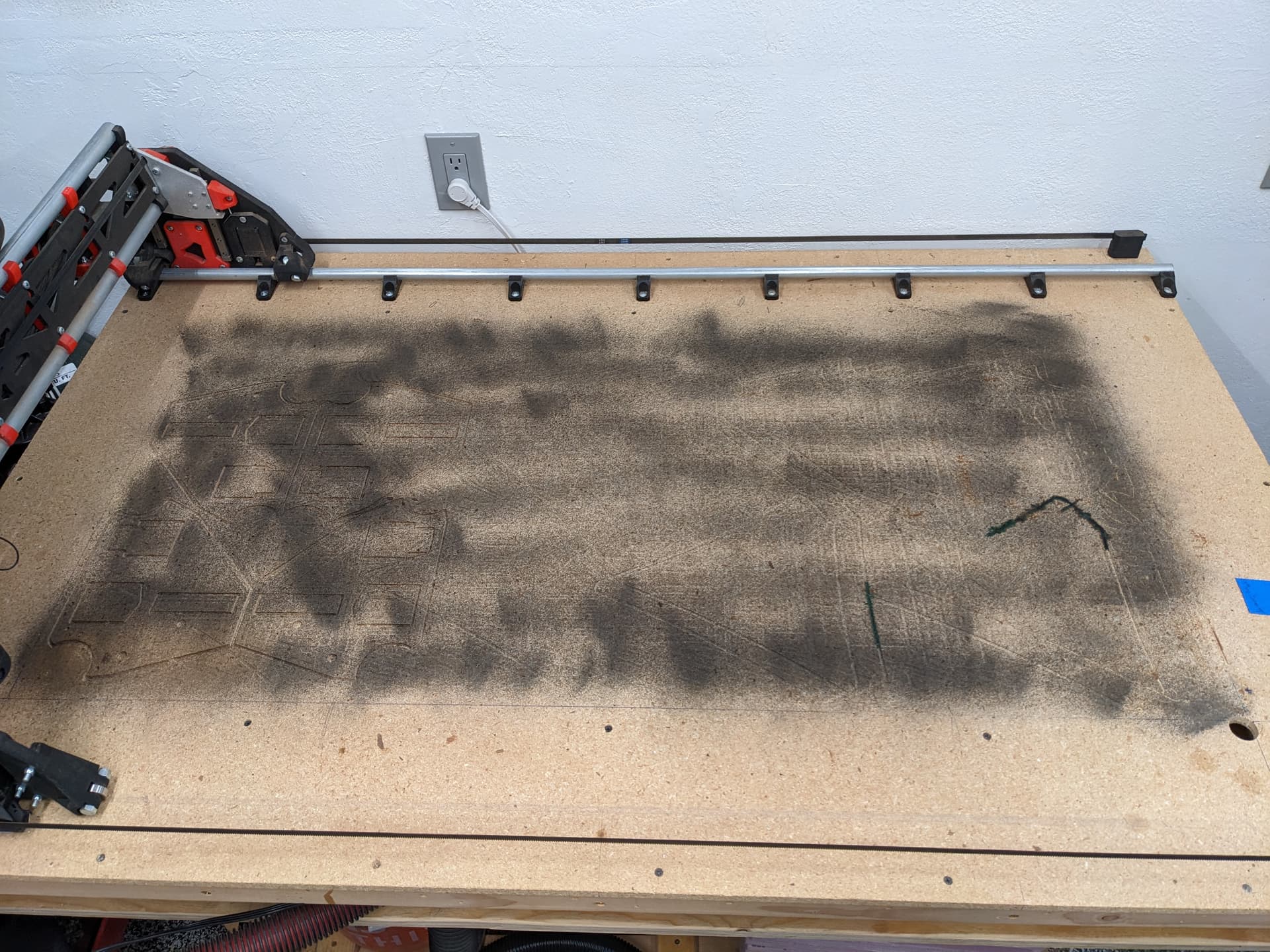
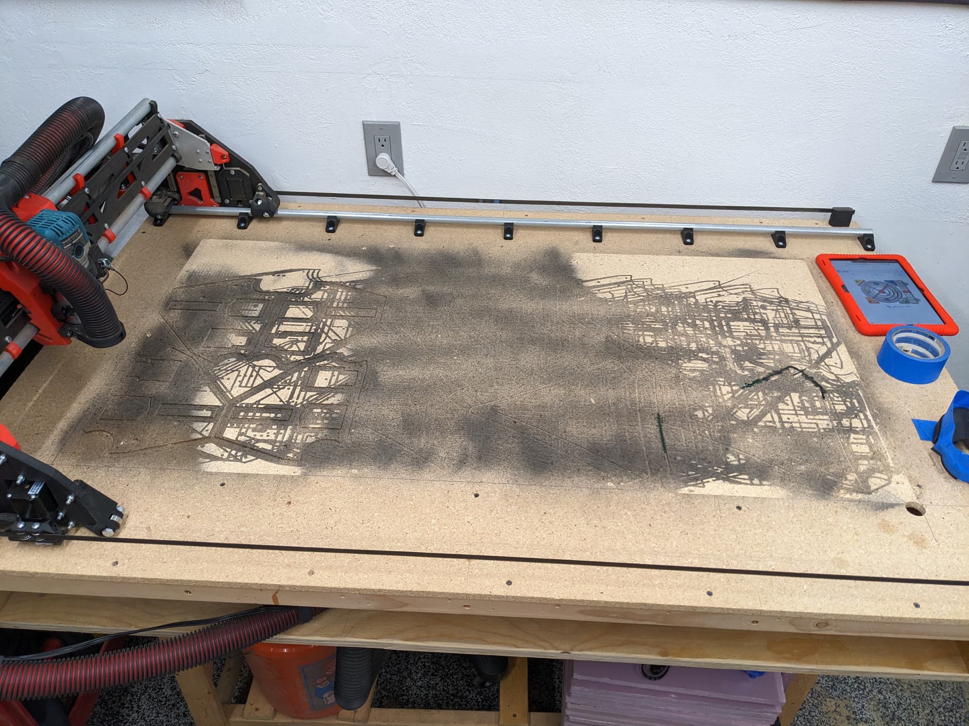
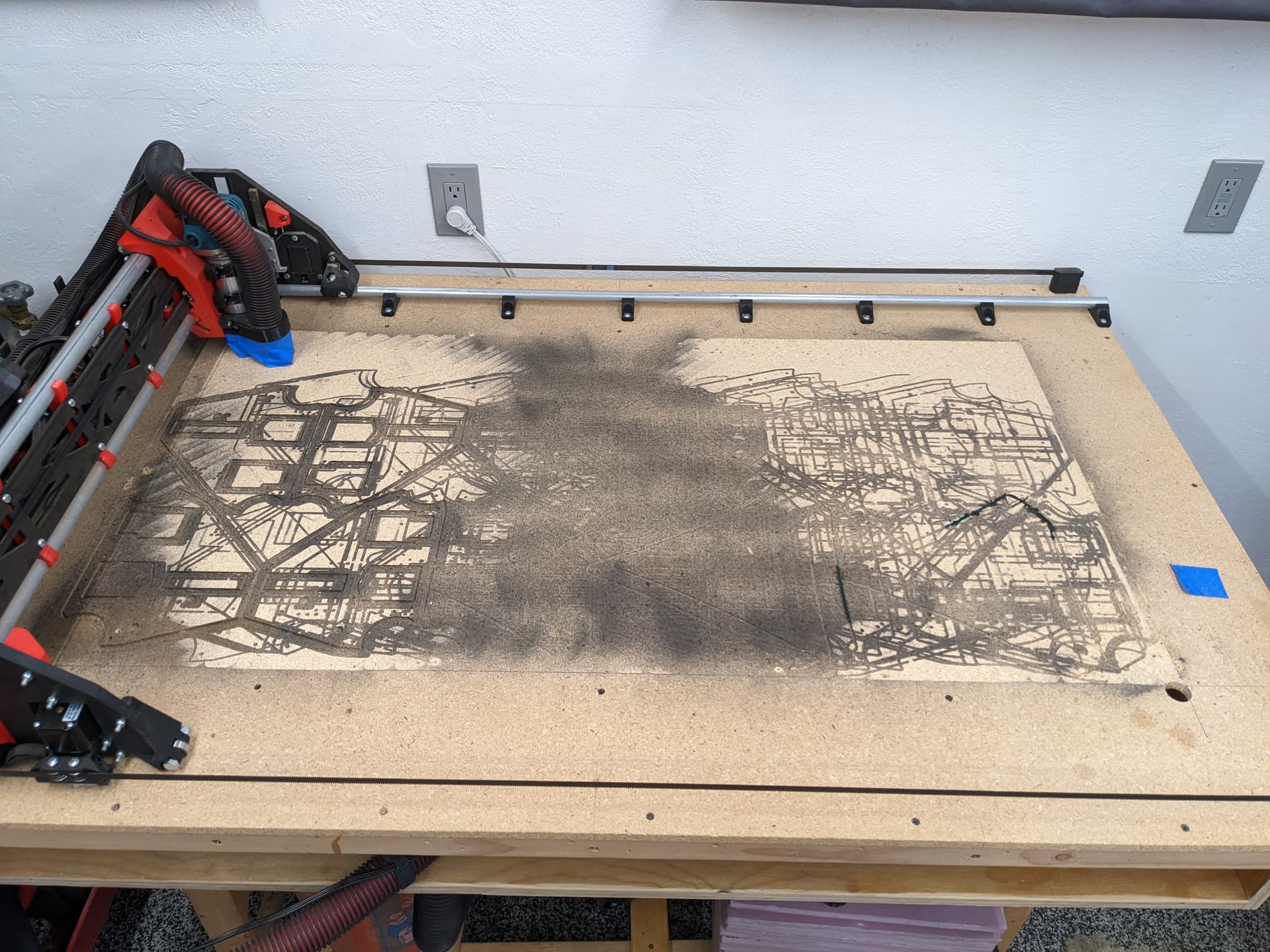
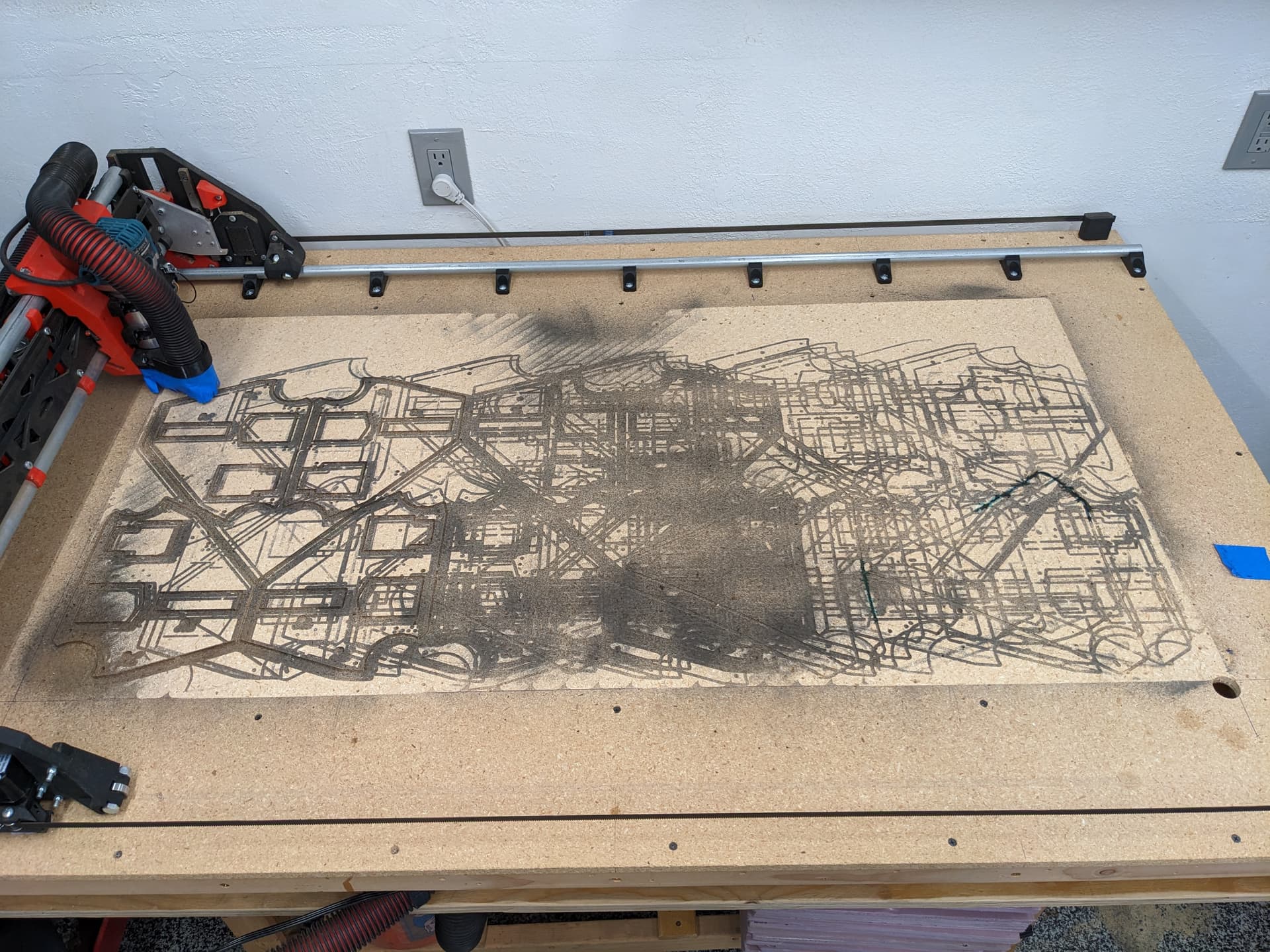
I then surfaced my bed 0.2mm at a time. I hit the bed with a dusting of black just so the previous jobs still show clearly.
The red circle shows the front to back tram issue. Right at the end I turned the last three braces about 1/4-1/2 turn looser. Then the CNC did the perimeter lap, you can see the green line, looks and feels flat again.
So, not sure of anyway to test for this other than some calipers at each brace to test the rail distance?
Table, or workbench? Something collapsible for taking to RepRap, and/or will appeal to folks with limited space, or contractors/businesses on the go. Maybe Paulk inspired, maybe even ends up on his channel as one of his workshop tour videos (a boost for both of you?). Curious to see what you’re up to. Guessing many of us are…
I was just thinking some sort of easy torsion box. Use some 1X3-4"'s for the Y and CNC out some X plates. Legs are up to interpretation.
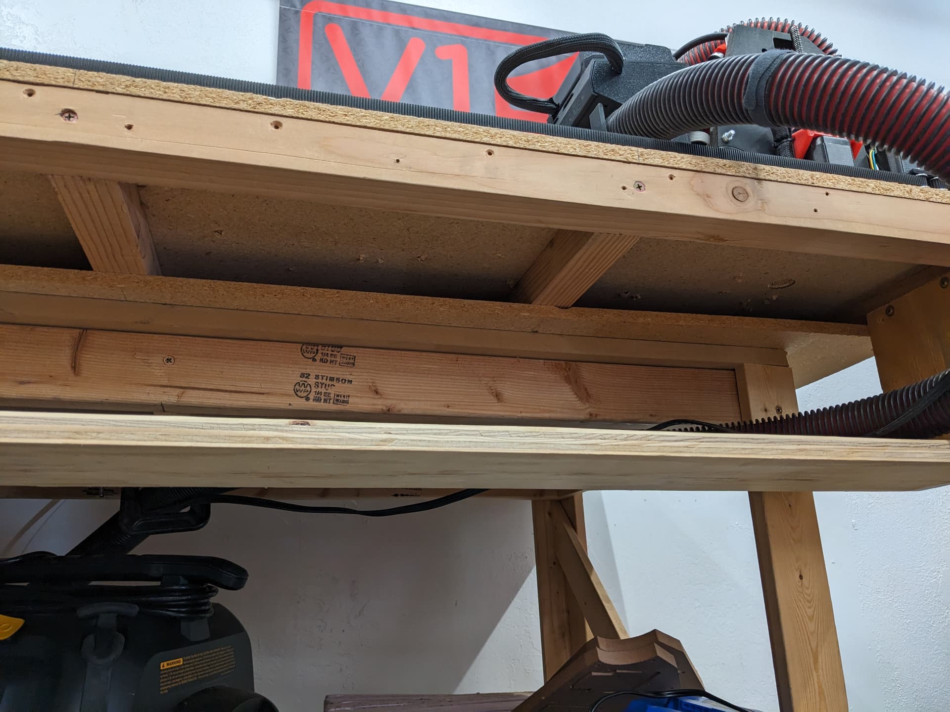
I have a couple ideas, but this is one of those things, you need a CNC to make a CNC’d table… Not everyone is going to like that. Now that I know how this janky little table has held up for all these months I don’t think we need 12" thick tables, this is 1.5".
I think the biggest issue is 1by material isn’t always the same thickness across the board. Prolly close enough though. The hardest thing I found was finding a flat enough surface to build it on. Garage floors aren’t exactly flat, and if your frame material flexes enough to conform to that, then once you screw/nail down the skins, it’s going to keep that contour. That’s generally why torsion boxes have a taller grid. Less up and down flex. At least that’s my understanding.
That would explain why it is smooth in the middle on my table and a little off on the left side. You were wondering how and where I screwed up that badly, but that explains it. So maybe even more butterfly wings on that side.
The LR can’t cut pieces long enough for the Y axis so they would need to be two pieces if there wasn’t an easy way to get something easy…a Table saw would do the trick but I think those are fairly uncommon these days? Or at least with this crowd in the forums.
Flood it with epoxy or floor leveling mix like when you do tile ?
Man I am right in the middle of building my table and I have re visited this like multiple times.
I talked to the wood guy at work he said we could do a biscuit joint and that would work.
I was looking at these
“Wings” ppl do, like I want to make a table that I can mount on a 4’x8’ table but the overhangs and stuff mess me up.
Damn wood everything should be metal lol
I usually make use of my table structure, for the LR2 I levelled it, then sort of built the top upside-down. You can do this with any two parallel beams like a pair of sawhorses. If you are looking for a very large table it makes even more sense to sort the frame out first. If you do visit the post below check out the one before and after it for the full picture
Uhh…
Before I put my LR3 together I think I want to understand what is happening.
The braces on the x-axis were too tight? That pushed the y-rail held down with the rail blocks further out?
Is it because the table isn’t level so the y-rail undulates along the length?
Or does the y-rail have a slight curve to it?
I’m confused, which is not unusual, but may not be the best state to be in as I close in on upgrading my LR2.
The last 3 of mine were, so that pushed the bottom of the core out about 0.025 degrees on the far end. Normal day to day use never showed this as an issue since the day I built it. This was only noticeable with a 1/2" diameter surfacing bit and even then only slightly.
If you are worried, I think the best course of action is to measure your rails at each brace to see if there are any inconsistencies.
No issues with the Y rail, if that does have a warp in it the machine and the work piece will follow it.
I wonder if it’s not that they were too tight but they were tightened slightly out of line with the others. You could get a whole twist as you travelled x.
Maybe a long straight edge placed vertically on the front edge of the strut on either side would exaggerate the twist so you could see it.
Yes I think we are saying the same thing. The last three braces were out of tension, compared to the rest. The braces themselves do have a minimum rail position and I thought I designed then in such a way that clamping would not push the tubes out, I thought the clamps would just open up…I was wrong. Actually just found this out here, Something isn't perpendicular
I set me tram near the 0,0 position so that was my reference. I will take some measurements today, and I have a old Beta beam sitting here so I am going to mess with the tensions to see what happens.
Both of my YZ plates are firmly grounded so twist on my build isn’t the typical twist some get when a plate sits crooked and the front of one side can be tapped on the table.
There are a few ways to adjust most aspects of the machine so I try to start with the most direct checks and adjustments first. A good example of this is adjusting the tram with the bottom tool mount. It has the most direct effect of the tool angle. You have an even finer adjustment using the top tool mount, I just never usually tell people to do that.
Maybe. If the beam was twisted the longer the beam is the harder that would be to see, or even measure. This is on the tune of 0.1-0.2mm out over a 200" diameter swing of the tramming tool. So on the 1/2" bit that is something like 0.001mm tilt. If my brain is doing the early morning math right. These weren’t ridges you could catch a finger nail on that was paint soaked would being deli sliced.