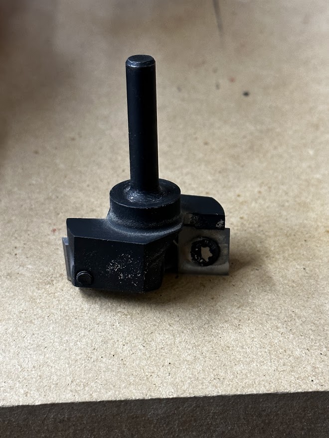
Trying to surface my spoilboard (for the first time), using the Vector76 utility and this spoilboard surfacing bit from Amazon. I’ve got the program set up to mill from Xmin to Xmax, with a 30mm stepover between passes.
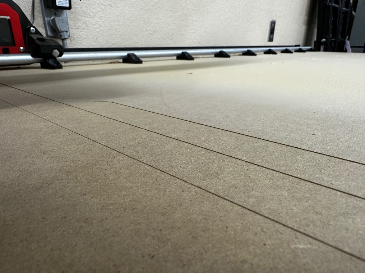
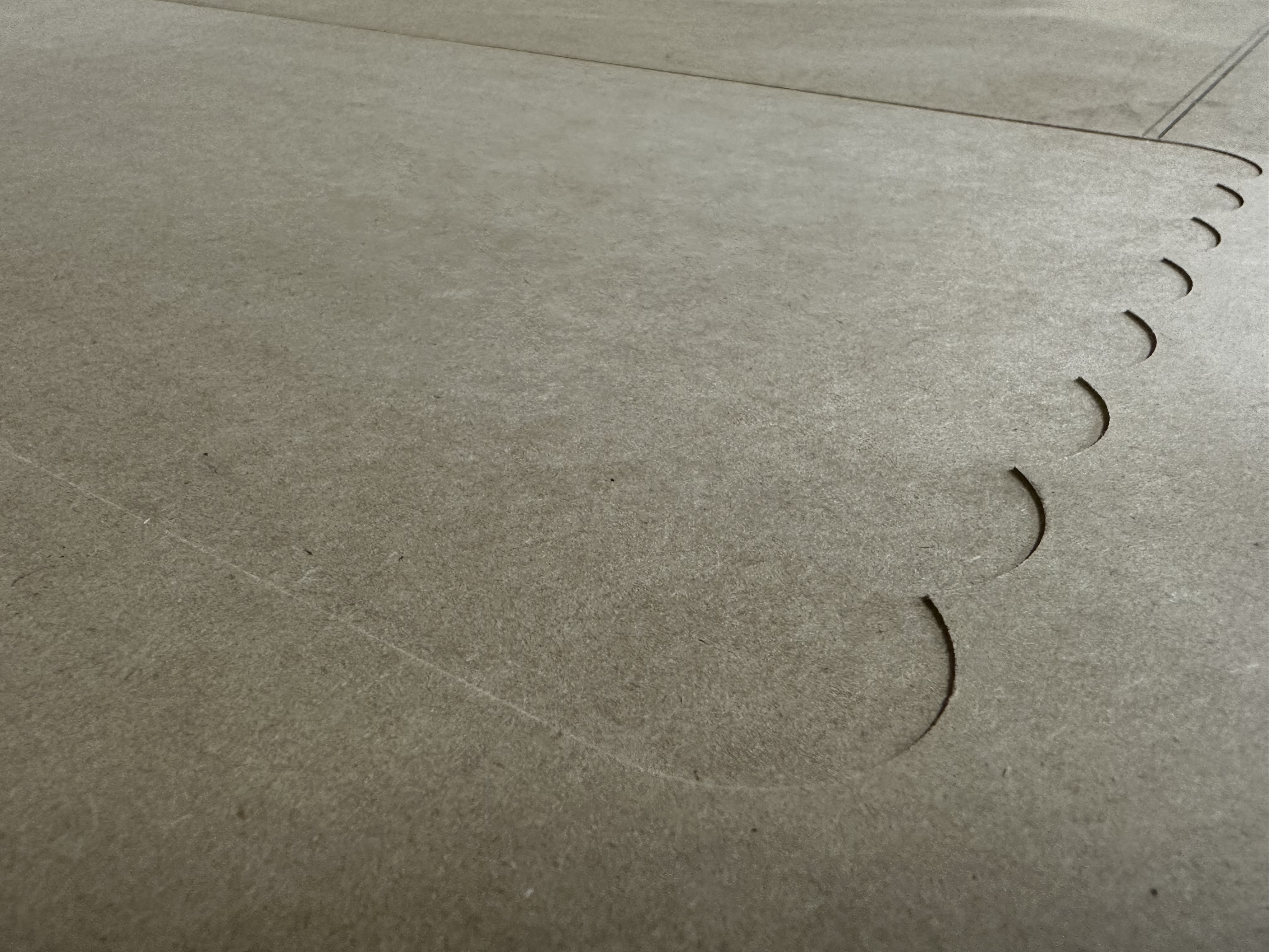
What I’m seeing is that the bit isn’t taking an even bite out of the spoilboard - the “right” side (as looking down the X axis) is digging in further than the “left” side, leaving a ridge between each pass as seen in the photo.
I’m inclined to think the shank of the spoilboard bit isn’t square (it looks to be welded to the , but maybe it’s the entire spindle assembly though I’m not sure how it could be. Here’s a photo in case someone can see something I’m not…
Using the biggest bit you have other than your surfacing bit, “surface” a piece of scrap MDF and see if you have the same problem. With stock, “surfacing” is often referred to as “facing.” If you don’t have an issue with the smaller bit, then it is likely your surfacing bit has an issue. If you do, then:
Verify your leg lengths and the height of your tubing relative to the spoilboard.
Check for any looseness of your core. Grab your router and just attempt to gently move it around. If there is some slop, you need to fix that before surfacing.
Search the forum for the term “tramming.” Tramming is the process of shimming your router so that the router is square with your spoilboard and machine. While there are fancy setups for tramming, just a simple tramming arm like this one gets the job done. You can even make a tramming arm with scrap wood and hand tools.
There is a bit of a chicken and egg problem between surfacing and tramming. You need to do at least a rudimentary surfacing before tramming will be accurate, but if the tramming is off, you will get ridges in the surfacing. I would suggest a minimal surfacing, then a tramming (if needed), then a final surfacing pass.
You can check if you have all the bugs worked out by surfacing a scrap piece of MDF before surfacing the spoilboard. Also, it is recommended you put in some hours using your machine before surfacing. Early use can show problems that need to be address…problems that would invalidate your surfacing.
I’d stick one or two strips of tape beneath the router on the top mount. That should do the trick. The bit is also huge, so every slight misalignment is visible quite a lot. With a “normal” size you won’t probably notice.
so a bent bit would definitely not give you the results you are thinking. I would say you need to tram your set up. I cannot find it right now, but @Ryan has a stl for a tramming aid. I believe your set up is not true to the board, so it is skewing it. Not uncommon and not hard to fix.
Yup, that is a giant surfacing bit and that is amplifying and tiny tiny tram errors you have a lot. Yours actually seems to be extremely well trammed and with a 1/8" endmill I do not think you would notice. But this is common, you do need to tram to use a bit that large and it is actually pretty easy to do.
Printables you should be able to cram this on or scale it to fit your tool. Just swing it around and shim behind your tool mount between the tool mount and core to get the swing as perfect as possible. I use small pieces of blue tape, and you shim opposite of any low part of the swing on the bottom tool mount. There are rare cases where you might shim the high part of the swing on the top mount. Simple tool, does the job with amazing accuracy.
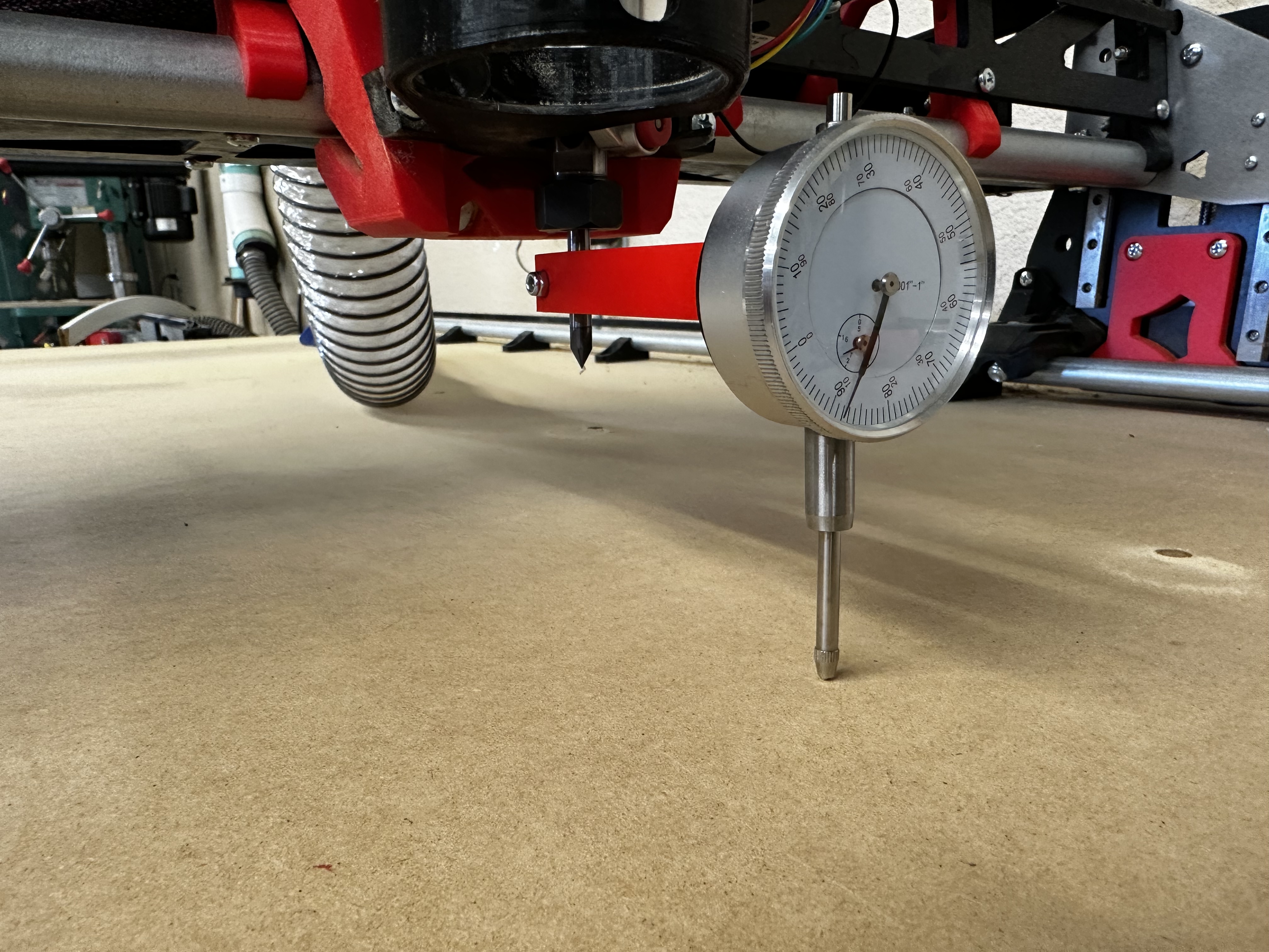
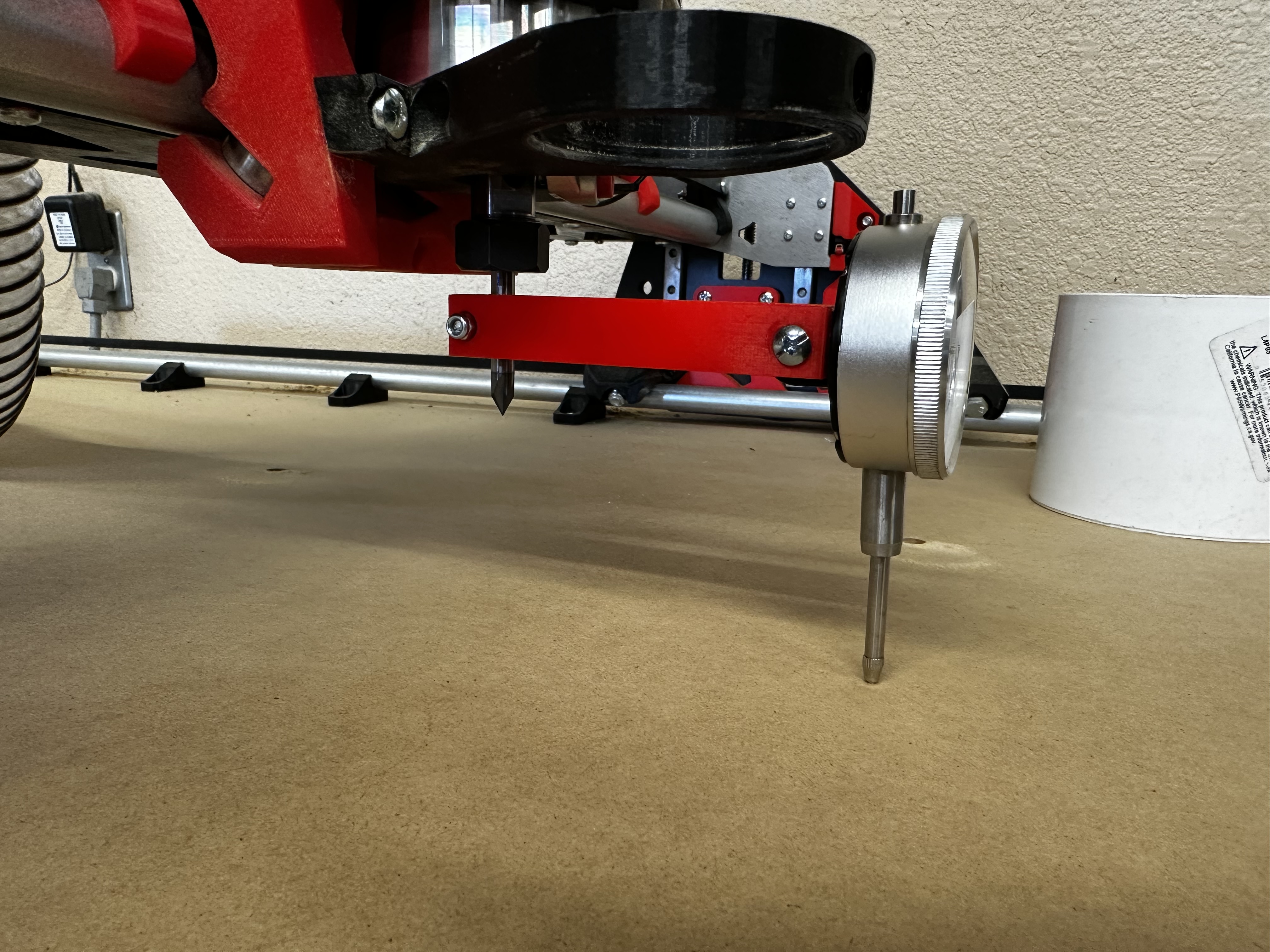
Seems like it’s gonna work great - though I had to remove the knurled nut at the top of the indicator to make it fit under the gantry.
Maybe overkill, but I think I’ll find it a lot easier to use than trying to guess at how far a screw is from the spoilboard. (If you really want to see some overkill, watch the YouTube video linked on the Printables page…)
Hoping to have time to tinker with it this evening.
Haha, I had the same problem. You don’t have to push it all the way on the collet, it just can’t fall down. See @vicious1, I am not the only one who is confused.
Just be careful. Those numbers will seem really big.
The tool does work, like Phillip said, just get it on the collet a tiny bit. I actually just redid my LR right before this post. I used a flat head screw driver to open it up and slip it on the collet.
The reason I bring this up is I don’t want you to chase Zero’s. Getting it perfect in a 8" diameter circle is not necessary, and using my simple tool will let you visually see how far off you are. Using tape as a shim my router is angled X 0.2mm over 8". That works out to about 0.05°.
So use the tool you have, get it to what you think is good then throw mine on so you can visualize your error.
Thanks for the info - I’m not going to get crazy trying make it perfect.
I started to write about how I didn’t want to use your fixture because it wouldn’t be guaranteed to sit square on the collet nut – but I just realized it doesn’t matter since I’ll be rotating the fixture from front to back in whatever orientation it happens to be on the nut…
It might be worth mentioning (as I have run into this resurfacing in the past, causing weird results), that you might want to also check to make sure your z axis leadscrew stub isn’t bottoming out in the cutout on the YZ plate when it is resurfacing.
So, 2 layers of electrical tape on the inside back of the lower router mount and I’m down to less than 0.4mm difference using @vicious1 ’s tramming fixture.