CNC-cut table for LowRider v3 (parameterized, for cutting full sheets+)

The idea I am working is not fully realized, there are a few things to work out still that is why I have not taken it further.

Some tips, The cutting area should not be centered, dimensional lumber is not a good idea, the top should be different height from the arms, and the arms are also longer than the top surface. It kinda looks close but it is missing some things.

2 Likes

3 lengths of tubing in a triangle keeps the X axis straight , could you use it for the Y as well?

1 Like

Got it. The backend of the movable gantry eats up more space than the front. That affects the Y being off center. Also, I think your design showed more real estate on the side that has the Y EMT rail. Mine does too.

In my design, the side extension with the Y EMT rail is wider by 1". It’s 4.25" wide while the other side is 3.25" wide.

Re. the length and offset of the side plates (sometimes called side “rails”) that the LowRider runs on, I have not yet designed them. They would be easily offset as needed for the backend of the movable gantry eating up more space than the front.

Does all this cover the offset enough?

Was your napkin sketch idea based on MDF? Something spliced / scabbed together?

My thinking was that the “top” would have two sheets of MDF, one meant to be more permanent and attached and not intended for replacement, and another on top of it meant to serve as a temporary spoil board that would be intended for replacement. In this illustration, the first later on top is 3/4" MDF, and the layer above that is 1/2" MDF. Does this sound right?

Also, in this illustration the side extensions have “something on top” that is currently showing at 1/2" thick. If not dimensional lumber, and instead MDF, then I don’t think MDF that long can be bought in my local area (maybe from a kitchen manufacturing place). Nevertheless, does this arrangement seem like the height difference you had in mind? i.e. the LowRider is riding on a slightly lower plane than the material is sitting.

I’m not sure what this means. Can you help me understand better?

Thanks for taking time to look it over! I know you’re busy.

Ugh. Don’t get me started…

I’ve been thinking about this too. I have a draft already of a torsion box frame for the LR, but not parameterized. Mine is based off of what I can transport in my car, and still be able to cut stuff that I can’t transport in my car.

My LR3 beam span is 47.5" so that I could cut the struts from a 24x48 sheet, but I am thinking I’ll rebuild to get a 49" usable span.

My current table is 5’ long, but the rails are 6’. This lets the gantry address all of the 5’ table.

2 Likes

That is driven by the dims on the calculator page. It is a defined number.

Just do it the way you think it should be done, if and when I get time I will work through the ideas I had. I was just offering some tips. Torsion boxes can be simple or tricky, There are things that need to be tested in my oppinion.

We were discussing it in that thread. A table saw or some sort of trusted circular saw guide is needed…or we were going to do a two piece Y. That is the part that has to be tested before I would release it.

2 Likes

@vicious1

Thanks. Got it.

To all:

Merely for purpose of collaboration, input, etc, and in case it helps anyone, here is a link to a viewable online Fusion 360 file of my work today, and I will also attach an exported Fusion Archive file of the work (below).

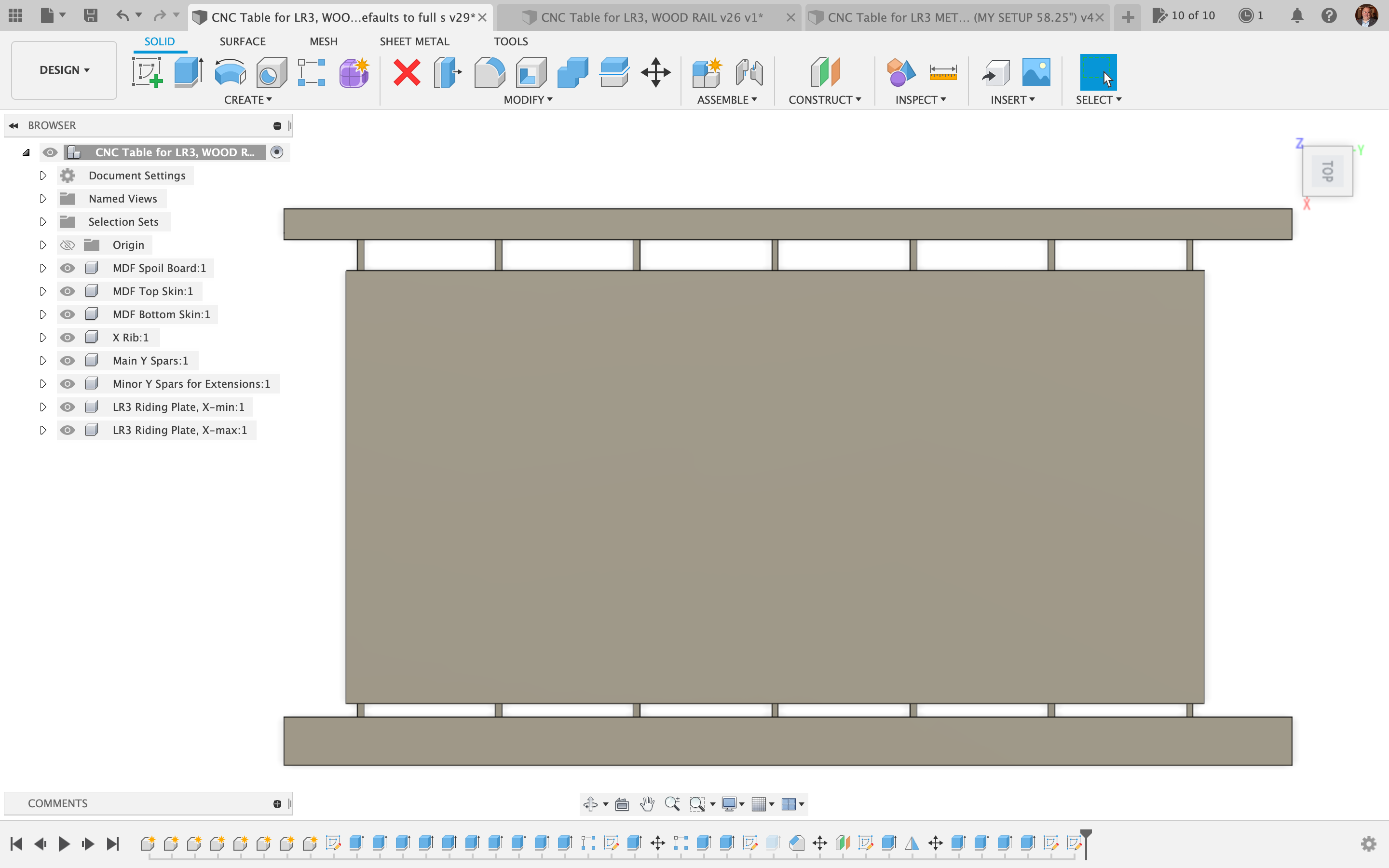
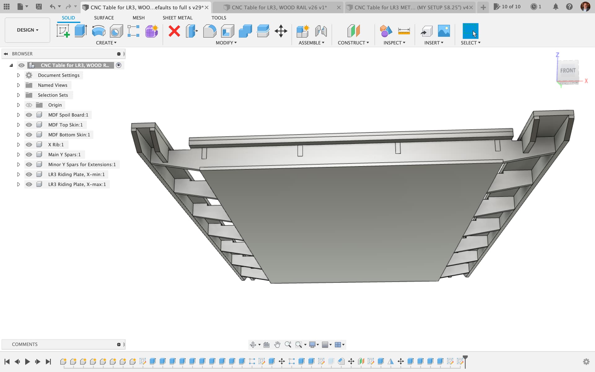
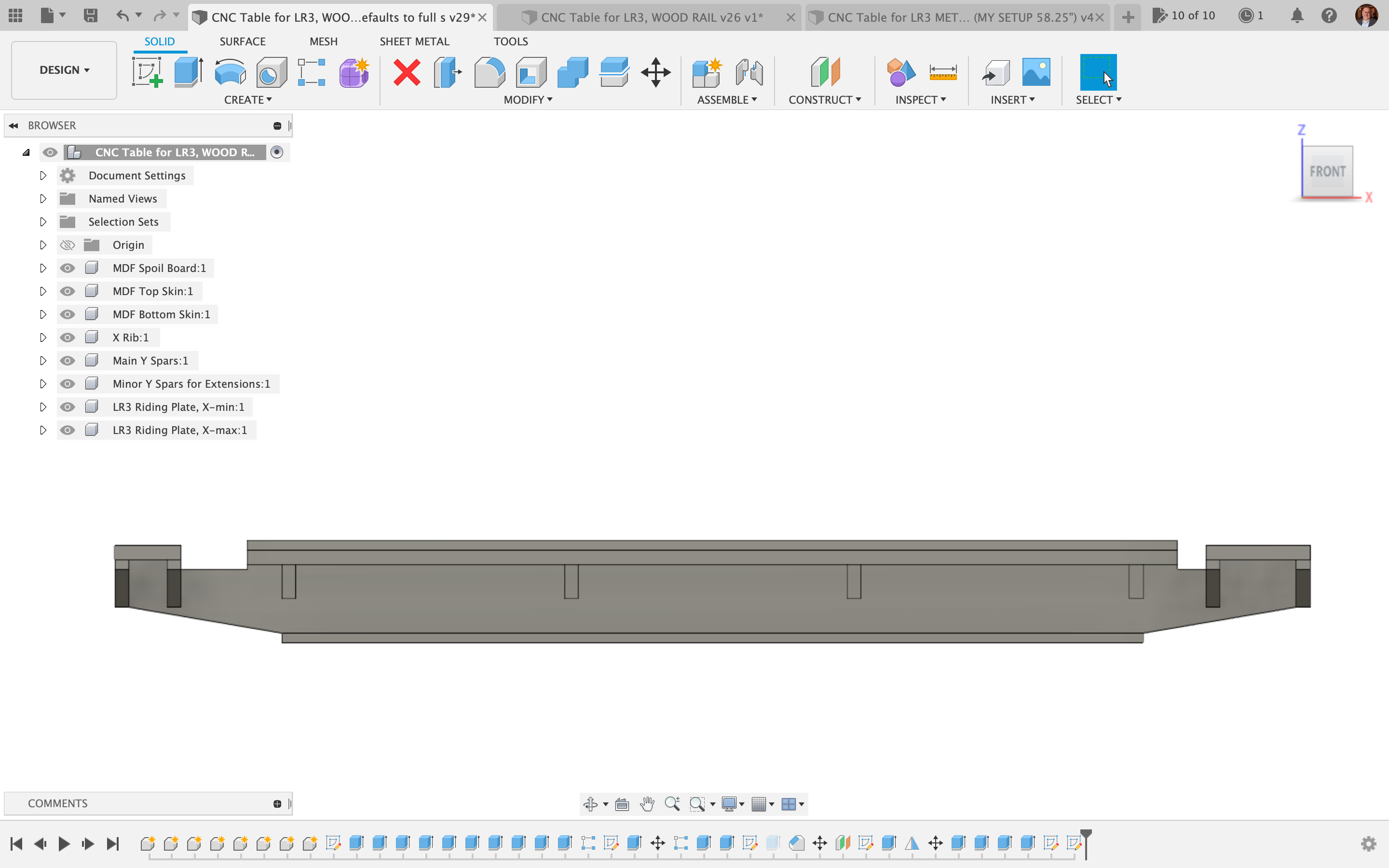
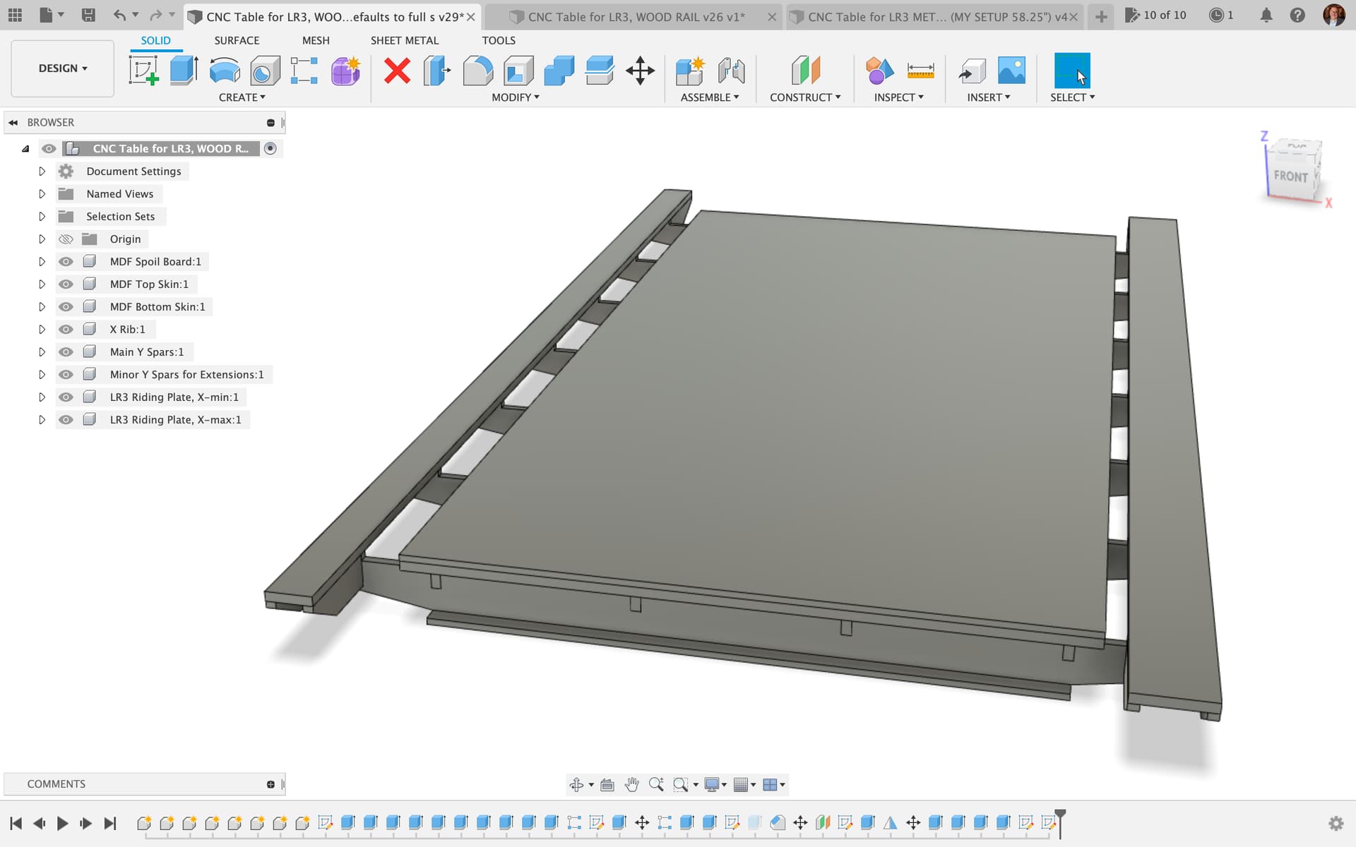
Update Apr 12, 2023: pics shown below — streamlined version that is doable from a single sheet of plywood (all except the wooden side extension rails), and the Fusion file is updated both for online viewing and the download links I’m sharing.

Click HERE for accessing the following

DXFs for TABLE WITH WOOD SIDE RAILS:

DXFs for TABLE WITH METAL STRUT SIDE RAILS:

NOTE: Ryan has now released a plan for a table that can also be CNC cut. I took many cues from both his napkin sketch and the table he released today. Here are a couple of overhead screen shots for comparison:

Ryan’s table…

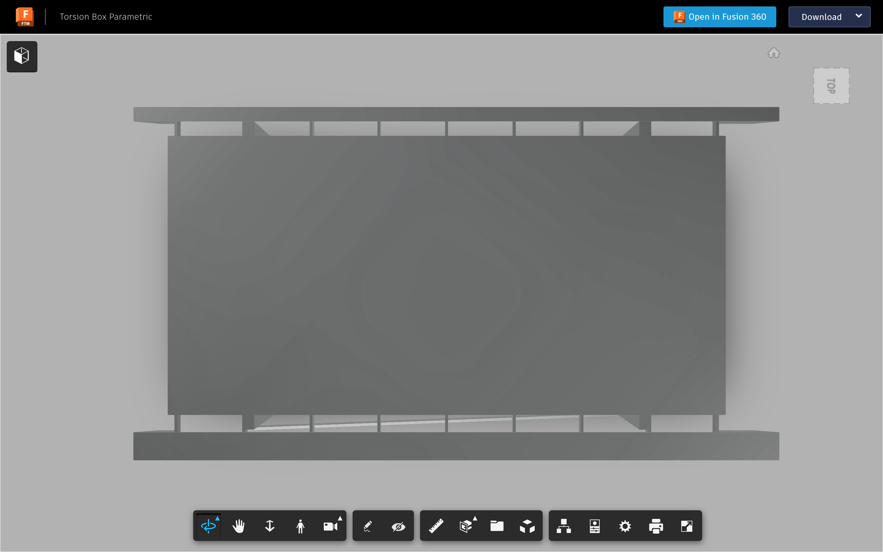
Compared to my table.

I will complete outputting mine, but since Ryan’s is available, I will not be offended if his is used instead of mine!

1 Like

Please note that I dug into how to parameterize the quantity of ribs and struts, etc, so that they should change as needed if someone edits main cut width parameter or the main cut length parameter, etc.

Not sure what you did, but usually how I do that is to use a rectangular pattern with the count set to something like 2+int(tableLength / 250mm) to have struts less than 250mm center to center. Then set the pattern length to tableLength - materialThickness and it should work out. It might have one more than you think it should for an even multiple of 250 but that’s why it’s less than 250mm center to center. I’d likely use a larger distance anyway…

2 Likes

One little tidbit I had to find out, was that the params default to a unit, and for quantities of [ribs/struts/etc] the quantity param has to be unit-less. So if anyone is trying to do this, and Fusion 360 just won’t accept your quantity param, check the units. Also, I could not see a way to change a param with units to one that is unit-less. I just deleted the param and re-added it the right way.

1 Like

Some links and videos with helpful info about F360 params:

2 Likes

Right. Which is why my calc has tableLength/250mm tableLength is a parameter in mm so dividing by a number of mm results in a unitless count.

2 Likes

@Ryan, despite what I said in a video I recorded several days ago, please don’t feel any pressure. It’s all a work in progress. I did finally get the video posted. Link up soon wherever is best place to post it.

EDIT: Ok, the video is now over here:

1 Like

No Worries. My head is down until the machines ship out to Colorado. Keeping all the printers humming to stock the shelves. 4 days is longer than they have ever been off, I think. Hopefully Rmrrf nudges sales a bit higher to afford to get some help in for a handful of hours a week. I am so close. The first employee is just super expensive.

Then maybe I will get back on pre-covid track. If any of you remember, we were all headed to Mrrf, and I was super excited to hire someone when I got home. 2-3 weeks(?) before Mrrf lockdown started. Sales spiked and I couldn’t hire anyone then supply chain issues. I finally, just today, got 2 months worth of Skr’s ahead of inventory. I have been stuck 3 weeks behind or more for about a year straight.

I guess that is a long way of saying something is changing when I get back so I can spend time making more things (or finishing the details on the things I have started, at least), and get some more Forum time. Fell like I am never in here anymore.

7 Likes

I hear you! Thank you for all you do! From my perspective as a pastor, the Covid fallout was a nightmare. And for many, the fallout is still happening. Some key decisions about how to approach it made the “cure” worse than the disease.

1 Like

Doesn’t feel like it, you answer everyone with absolute patience and are always present.

As teachers we learn that kids have to have the feeling of being supervised in the breaks. That’s what you absolutely achieve here. Omnipresent Ryan. :slightly_smiling_face:

1 Like

OK, so I mentioned above that I had intention of creating a version made for metal struts (aka Unistrut, aka Superstrut). Well, I have that version just about ready to go. See screen shots. This would get around the issues of having to scab together some type of wood long enough for the sides that the LowRider rides on.

Regardless, I welcome input and help on how to design the legs / support structure for the table. 4 legs are easy, but they would require some form of leveling. Casters are desirable, and there are heavy duty casters that also do auto leveling (transition from movable to immovable) and they are affordable (for instance on VEVOR website). So four legs is an option. There is also a method of doing 3 legs, and a method of doing two legs and a pivoting two-leg prong that accomplishes “three point” blended with “four point.” Thoughts?

1 Like

Also the thought occurs that it might be possible to do a version of this that accommodates drawers inside the torsion box cells. Thoughts?

1 Like

From my swiveling armchair, I’d limit it to the four end-cap cells. Access to the side cells would be problematic under the best of circumstances. Granted, if you’re making it parametric, nobody has to add side-access drawers, but I think they are a phenomenally bad idea. I’d at least put off side-access drawers until later… Also, don’t forget that you need to keep some of the face frame intact to maintain the torsion box, so the drawers aren’t going to be overly large. Probably bit/collet/tool storage (maybe even some clever tilting mechanism for longer bits if you need it).

2 Likes

My thinking was to (if attempting it), keep lots of the face frame intact, with added secondary drawer mount faces added to the plan, so the torsion box would be largely unaffected. I agree it’s possibly a not-good idea, but I like to try to leave no stone unturned.

LOL :smiley:

1 Like