The issue is all the dimensions are actually there. The reason they are not center about the endmill is the X endstop is not fixed. It is a variable. Then there is the variable thickness of the XZ plate.
1- if you take a look at the other side you will see the dimension, and the thickness of the plate called out, both sides are the same.
2- Variable due to the X endstop, but it is close to #1+half the core width.
3- Since there is no endstop it is fixed, so #1+half the core.
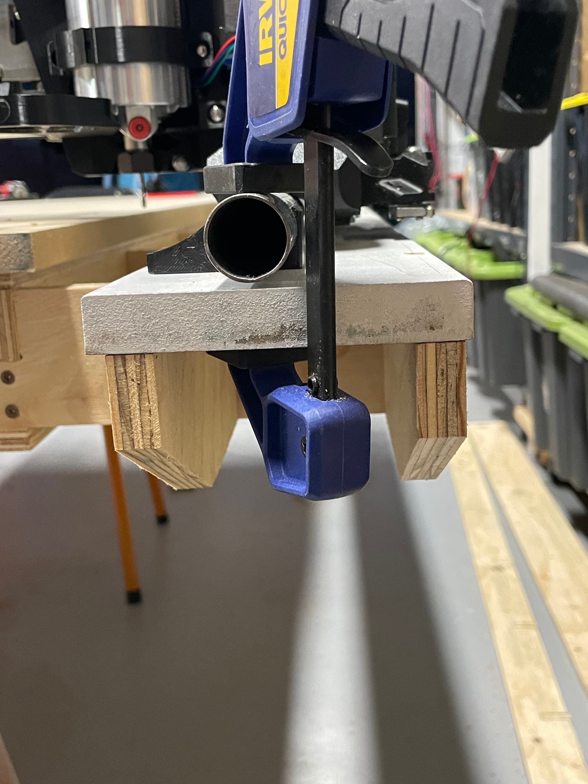
Just a note, I have already started to try rectify the offset issue, I have moved the Rail Runner, Rail side inwards 10mm so there is currently no overhang.
Image to show 0 overhang on the outside for reference.
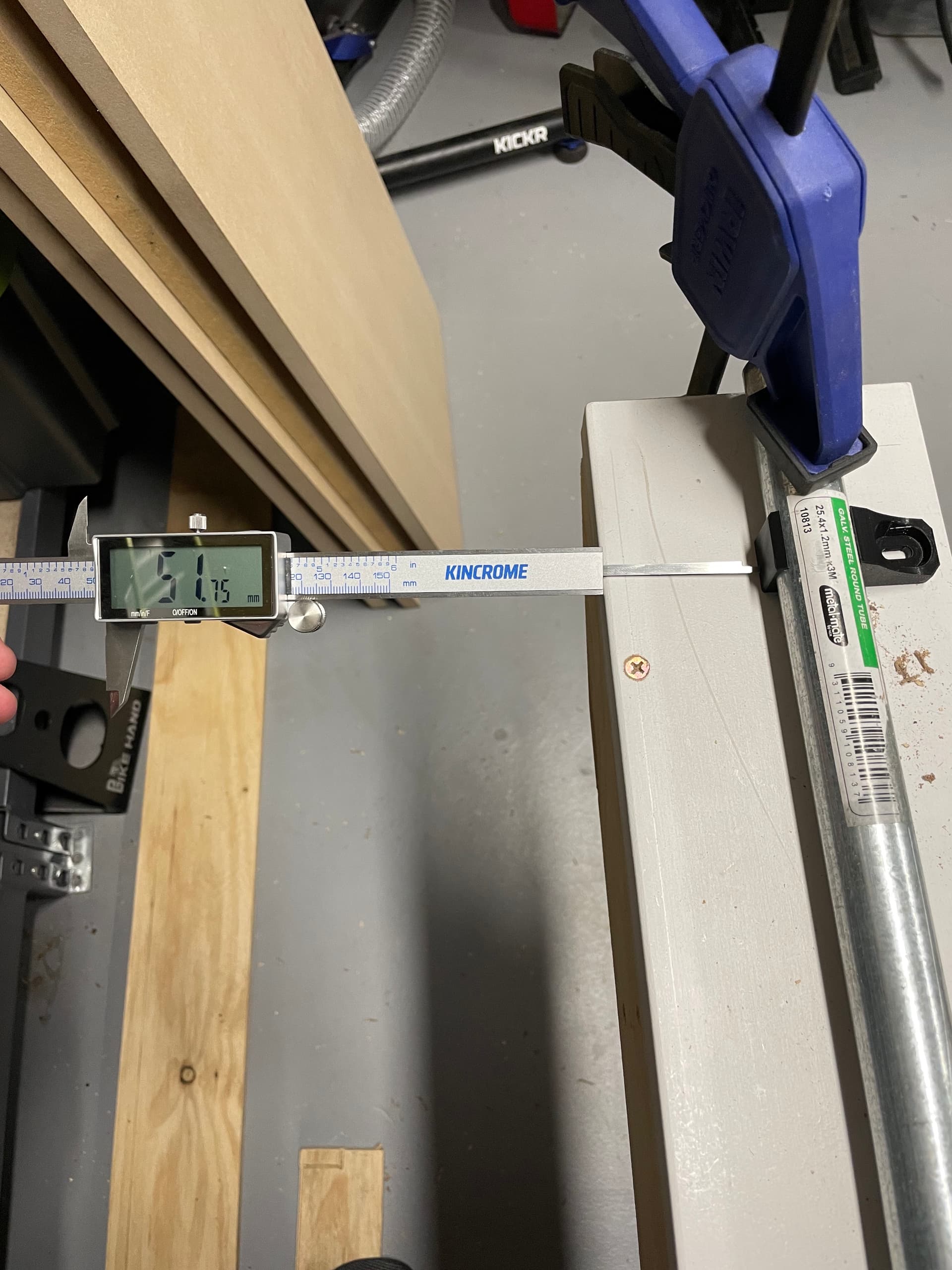
Taking the above mentioned 10mm into account I have for these test purposes set the rail to 51.75mm instead of the 61.75mm to give us the same net result.
I will definitely double check all of that in the CAD if this doesn’t account for it.
So what I am seeing is yours needs to move over 25mm to be ~centered. But that 10 you added is opposite of the 12 I was talking about…Hmmmm. The Though part is the extra 10mm you have is (or should be) from the X endstop side, which means you are even further off.
What are the outer dimensions of your rails on the table?
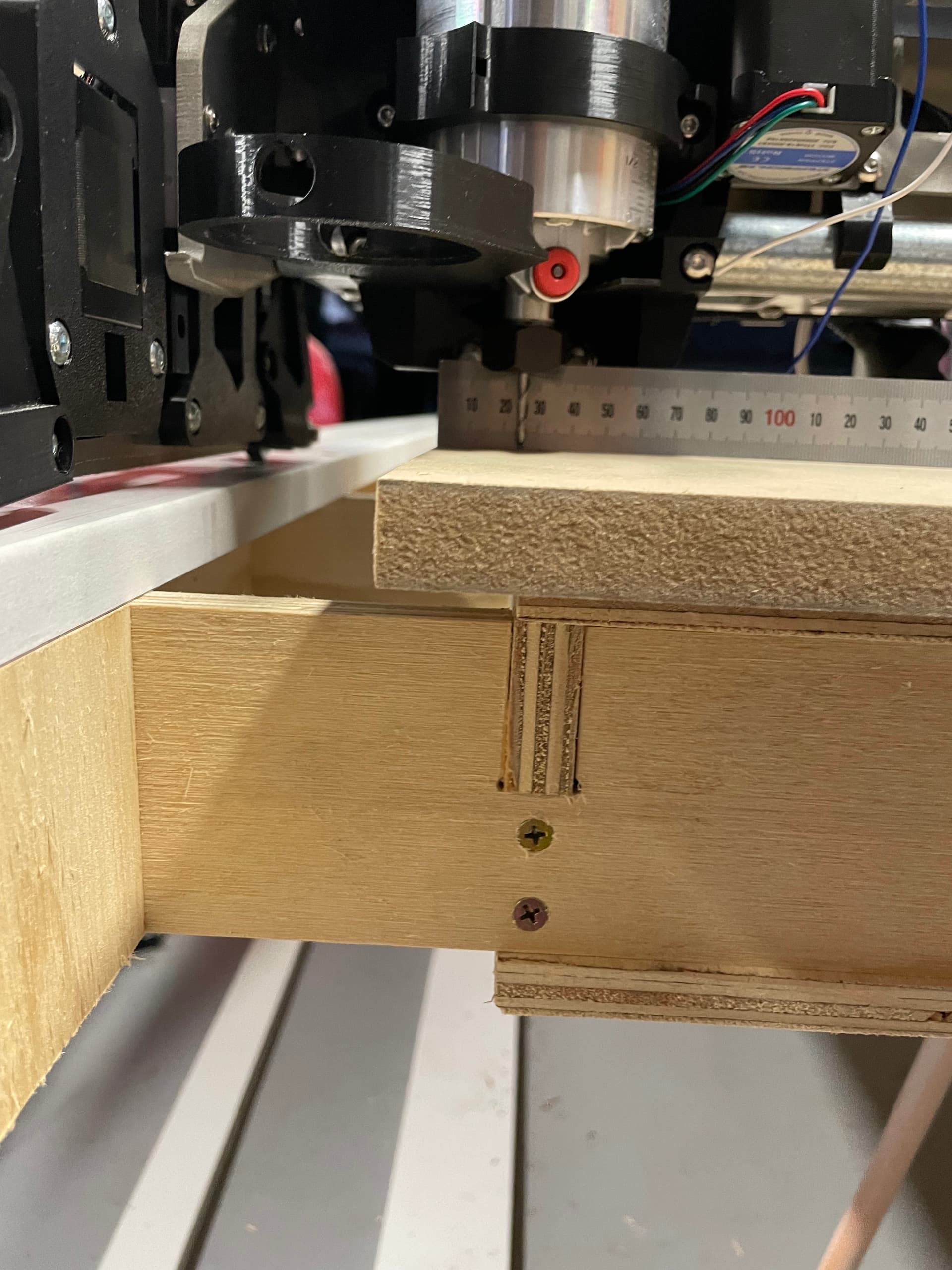
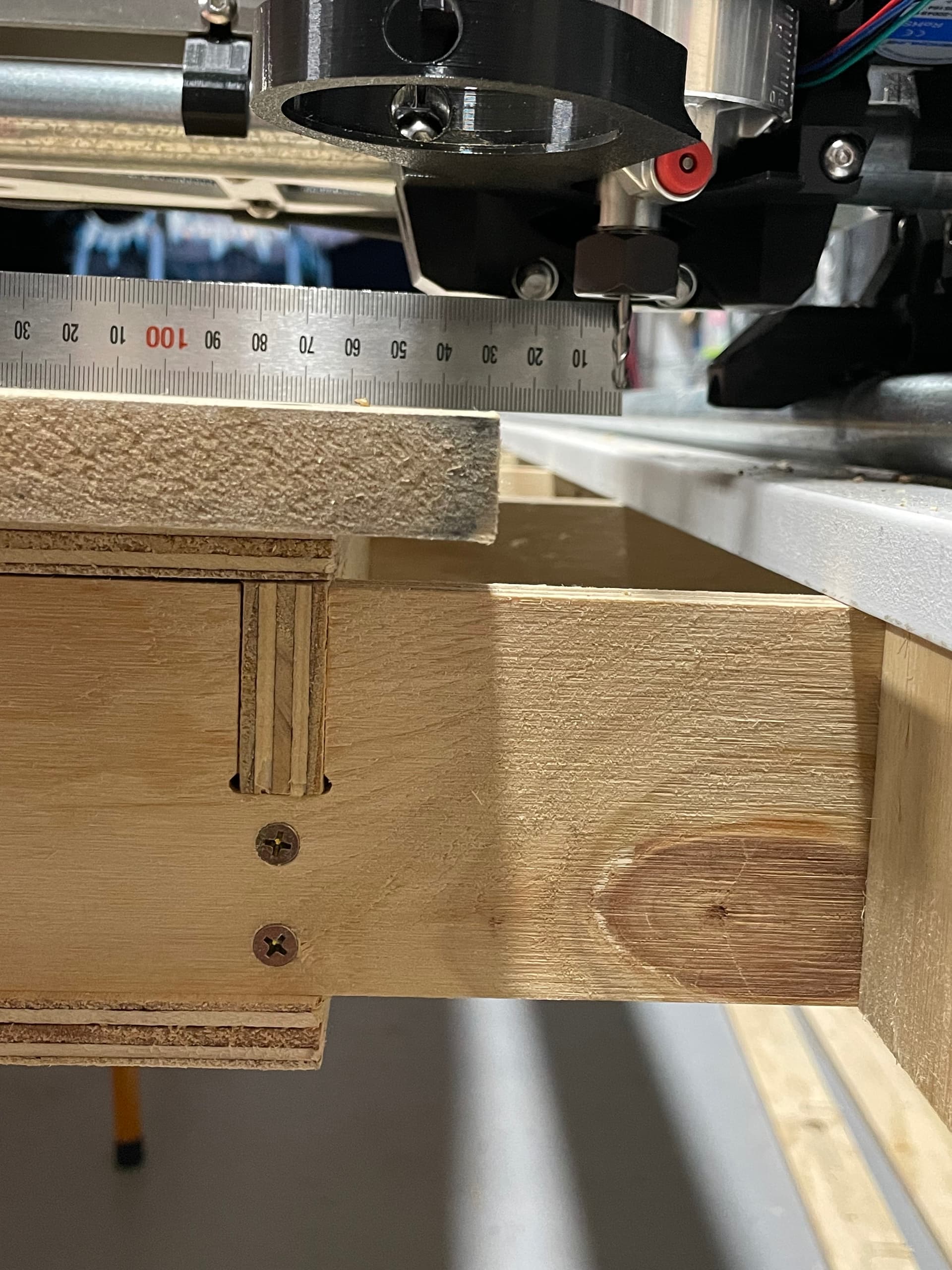
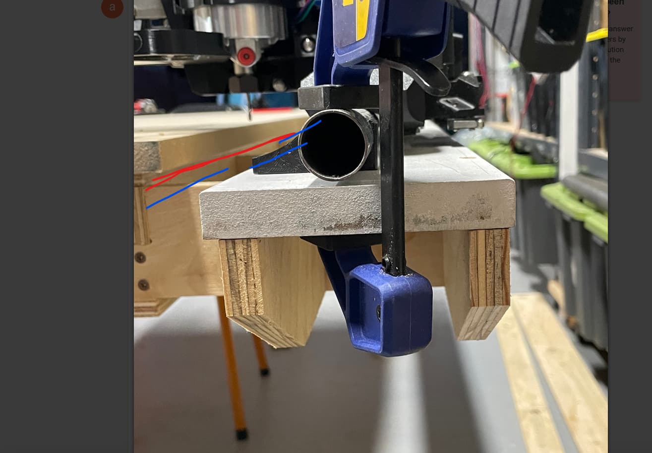
Looking at the picture you provided, I see you made the ribs all one single piece (red) mine are two pieces and offset (blue). How did you account for this in the CAD?
No, Not at all. That is why those dims look so funky, it is not an easy one to do. In hopes of squeezing out every possible mm I made a “hardstop” variable, and the XZ plate variable, and the entire machine variable.
You can see why I am always so hesitant to release CAD though. In this thread about a table with just a few actual parameters we can’t easily figure out why Anthony’s table isn’t as expected. I am always going to assume a CAD editing mistake. Trying to figure out where things are wrong isn’t easy. My machines are not fully parametric, not even remotely close. One tiny edit on the LR CAD and things might not fit together anymore.
TLDR version scroll to the bottom and ignore the body haha
haha, I feel your pain.
I been staring at it for days going back and fourth with the tape measure trying to work out what I messed up.
Yeah thats correct, mine had a 10mm overhang but as I was trying to shift the entire gantry across to fix the offset issue I slid the rail runner inwards.
I have been at it again tonight with a tape measure, my offsets are completely off.
I need to move the gantry over from my original position 30mm towards X-min.
I then also need to add 40mm to the opposing side.
117mm and was meant to be 68mm but instead of the 68mm end up using 92mm so I could offset things as a temp fix while I wrapped my head around things.
The formula is “Edge_Offset_X + Rib_Thickness” this came from your file.
I have actually just had a dig through the formulas and think I may have found the root cause.
My measurements tell me edge of rail runners to centre of router bit on the;
X-Min side = 150mm
X-Max side = 160mm
So total table width 1568 - the above 310 = 1258 (close enough to my measured 1260 total travel)
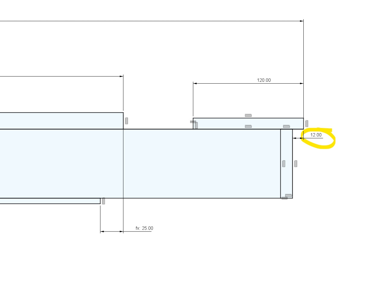
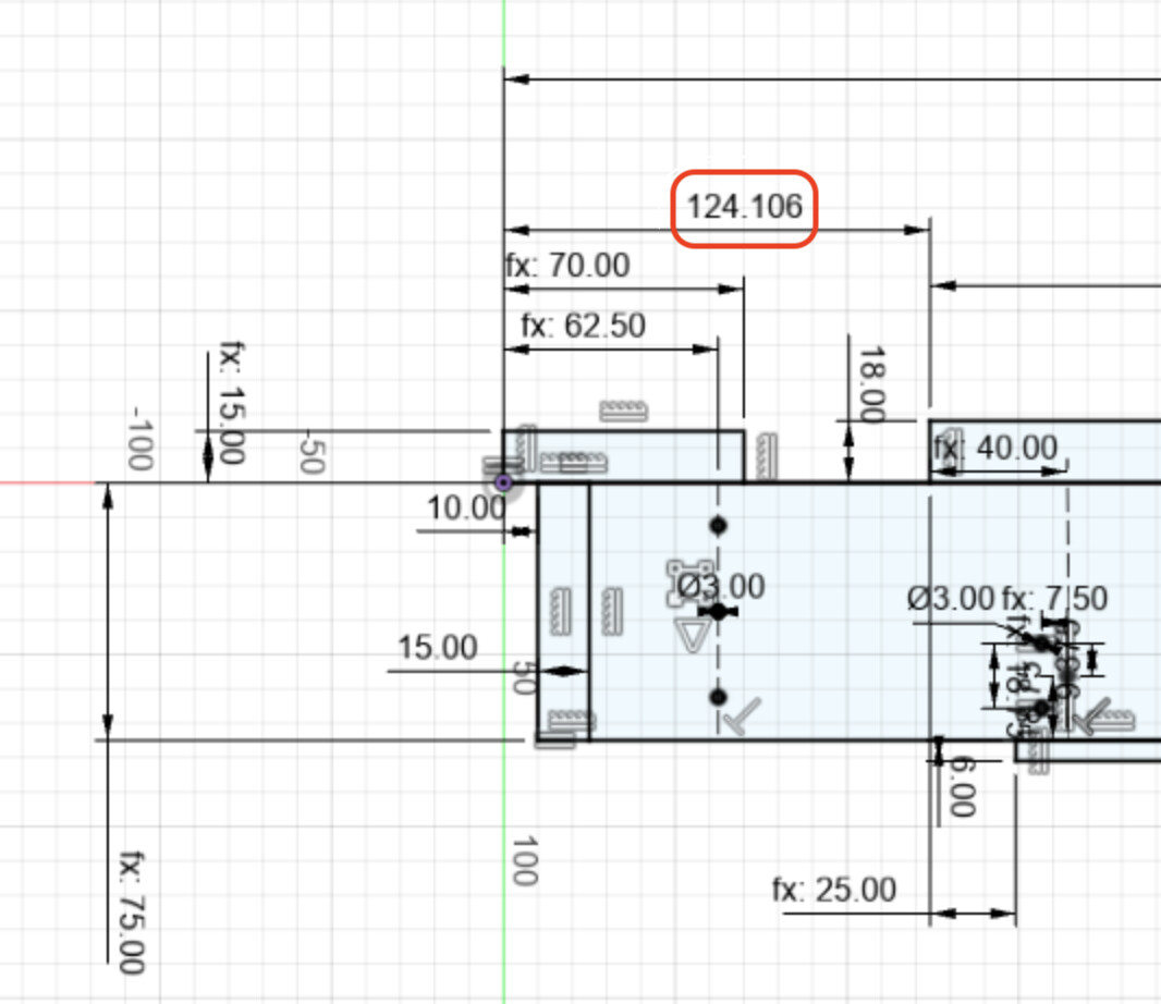
In the below screen cap I cant work out the math for the red circled value. (note this is the non rail side)
If I adjust this to 155 and my math is correct it will give me roughly 5mm of over hang on either side of the spoil board with the end mill.
I feel like this should actually be a formula? Something like
50mm ( edge of table to inside of YZ plate)
13mm (MGN Rail)
6mm (XZ plate thickness)
90mm (Half the core width)
maybe also + half of any extra width someone may add to their table?
The above math gives me 159mm which is a 4 mm off where I think it needs to be, I assume the router does travel slightly further on the X min due to the endstop vs stepper placement so perhaps the value should be less than 90mm, you will know better than I.
That number could be a formula, but it is going to change. X position is variable. The surface actually should get put on according to your build. So that number doesn’t really matter unless you know the exact position of your X endstop. 6 months in you might give that screw a bit of a tighten and move the location.
For me, I know I am going to be surfacing the table with a 1/2" endmill so it doe not need to be perfect, I just need to be able to get a 1/2" bit to swing off both sides. The larger endmills I actually use for projects is 1/4" and 99% of the time it is 1/8" so it is really easy to keep them on the table even after an endstop adjust.
I could make every single part there parametric but that is just not fun. Things I knew were slightly variable are made a bit big to meet the max standards.
If I get a chance I will triple check my cad with an actual cut part today but are we safe to say it was an edit error on your side not the original model? That and the surface needing a recentering to match your X endstop?
Yeah understood, I get there is a lot of variables and that somethings are better/need to be fixed.
Thanks, that could be helpful.
I didn’t realise the idea was to offset the workpiece/spoil board, I was trying to keep this at the dimensions set in fusion (25mm clamp area per side)
It looks like the same result in the original fusion file, give or take 2mm so id say no unless the idea is to offset the spoil board by up to 20mm?
If I offset it by 20mm, that means one side has a 5mm clamp area and the other side 45mm.
I guess that would be close the the min required for the 1/2" surfacing bit to reach the edge of the spoil board. (1/2 of 1/2" = 6.35mm) so the surfacing bit would clear the spoil board by roughly 1.35mm, and I guess this value would grow if there was ever any tension added to the screw/belt.
Technically you can adjust your endstop/belt to get exactly that. But you are going to get more travel, less clamping space. I think that is a good trade off. You can move your workpiece to wherever you want it, the only important thing is to make sure you can surface the entire plane. With a half in endmill you can pretty easily move the surface where you want it.
I’ll cut my test part asap and see what comes out of it.
I really can’t get my head around so many variables, and would like to have a crack at over-simplification.
Is it OK to go off on a bit of a design tangent on this thread or would you prefer I start another?
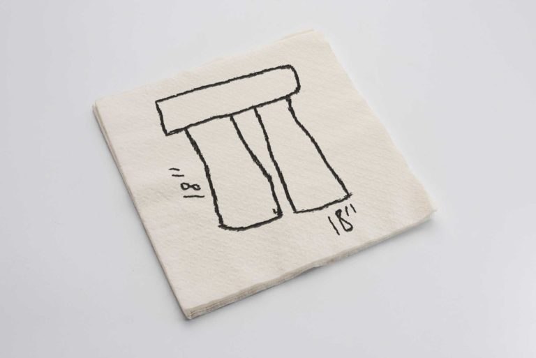
Oh, dear… You poor thing! Bless your heart, you mistook Stonehenge for pi. I admit, it’s a contextual joke. you have to know the source material to know that the stage prop that was discussed when the drawing was made was to be 18 feet tall, not 18 inches. It then becomes the centerpiece for a number of gags, including a couple of short people dressed as druids frolicking about the stage during what is supposed to be an epic metal ballad.