It has legs,
Or you can make your own.
It has legs,
Or you can make your own.
That drawing goes to eleven…
This is the way.
I’m a noob, so forgive me if this is a stupid question…
The boards on all of these designs are cut so that the long axis boards are notched on the bottom of the board, and the short axis boards are notched on the top of the boards.
The longer boards presumably have more propensity to bend over time, and with the notch on the bottom, it seems to me that the notch could spread apart under weight. If the notch were on the top of the long axis board, then theoretically the weight on the center of the box would cause the gaps on the long boards to “pinch” rather than “spread”.
Yes, the top and bottom skins would assist in preventing sag, but intuitively it seems that some benefit might be had by flipping the cuts.
But again, I’m a noob at this…
My design is not notched. My long axis is short segments fastened and glued in.
As for notched designs, once you add glue assume the joint is rigid (most wood glued joints are stronger than the wood itself) and notch side doesn’t really matter.
Sorry, I was browsing through several of @DougJoseph’s table threads when the question arose in my head, but ended up posting the question in this thread, not looking closely enough to notice that your design is notchless.
Thanks for the info about the glued joint strength. I didn’t realize that everything was glued together in the slotted designs, had it in my head that the slotted sections just slid together with no screws, glue or other bonding.
I think I actually first saw the notch on Ryan’s napkin sketch and liked it and kept it, then Ryan did not do the notch when he came in with his Fusion 360 file. Notch offers guidance, while “notchless” offers options for sliding one way or the other.
In addition, I think the top and bottom skins provide a bigger percentage of the stiffness than you are giving credit for. Like an I-beam, a huge fraction of the strength and stiffness comes from the top and bottom. I am guessing it is 90% or more.
Yes adding a notch or cutout would make it quite strong imo.
If it’s a after thought some square stock could be added and glued.
But it might not really matter. If your going for light weight and want to add cutouts in for storeage etc.
basically making is a semi monocoque structure.
Been following this in the shadows for when my silly idea doesn’t pan out lol. Great work ppl
Hello!
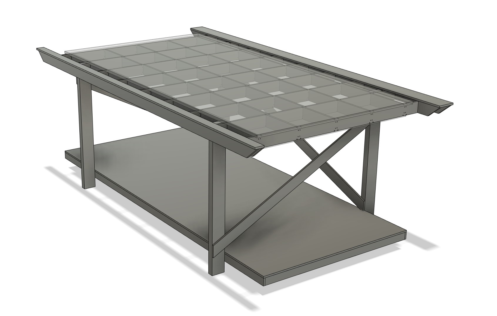
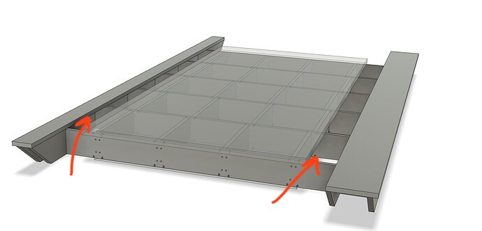
What are those channels between ”work area” and ”rail area” used for?
The core needs space to the left and right, so there does not need to be a spoilboard because it can’t cut there anyway.
Ah, I see! So I could fill those areas in and that would be okay?
You can but they might be useful. I think the channel on the left will keep things from going under the bearings, and on the right might be good to run the vac hose.
But yes, traditionally we all have solid tables.
Somewhat of a tangent, but for anyone considering an IDEX build, you need clearance channels left and right of the cutting area. When each tool is cutting, the other tool needs enough clearance to not crash into the table.
Assuming you are not deliberately cutting deep grooves in your spoilboard, you will need a channel depth that’s a bit more than the difference in length of your cutting bits, so when your shorter bit is at the spoilboard top, the longer bit is not crashing. If your bits are nearly the same length, then you only need a little bit of channel depth, and you might get away with just the thickness of the spoilboard and no extra grooves in the table.
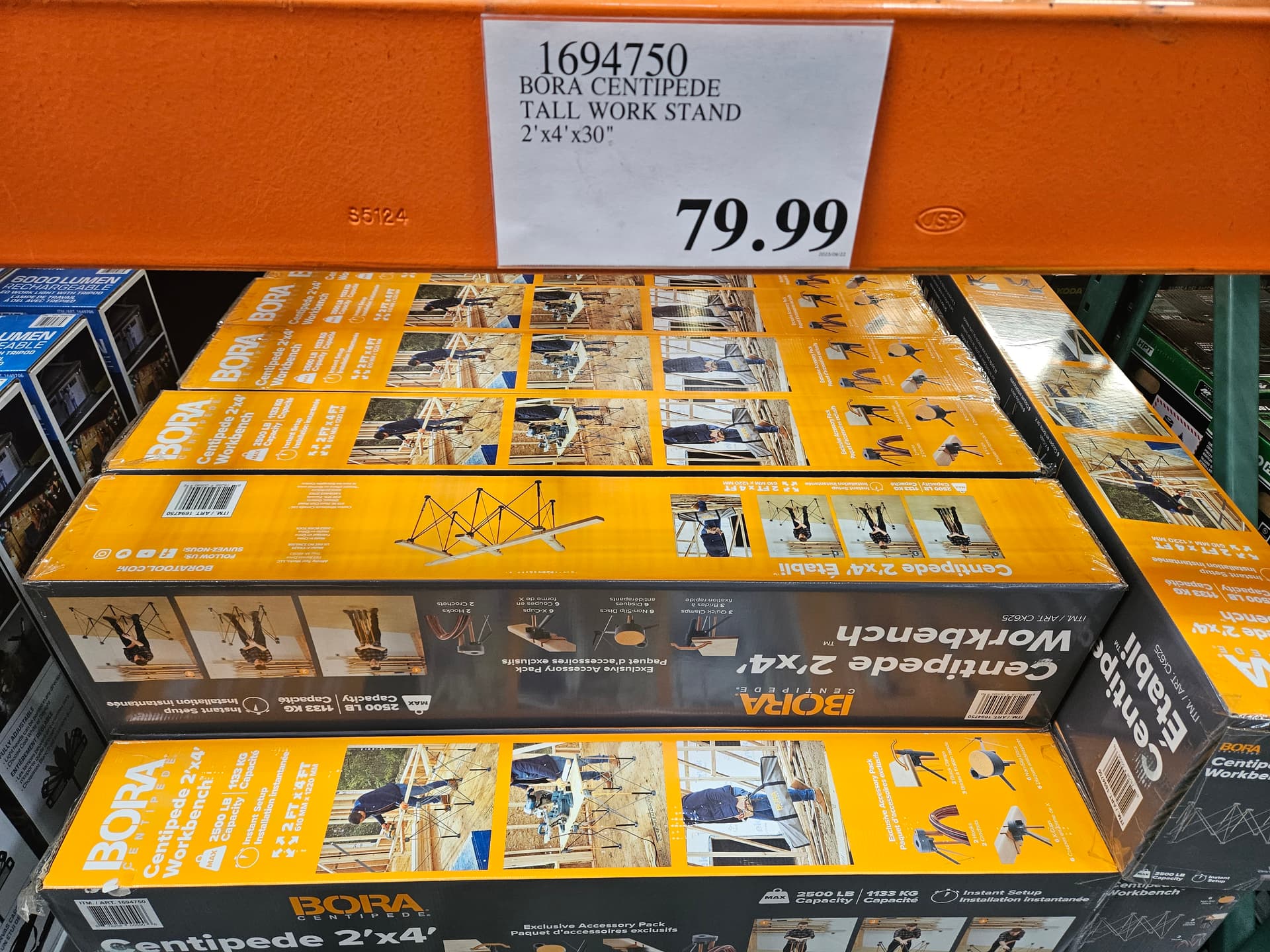
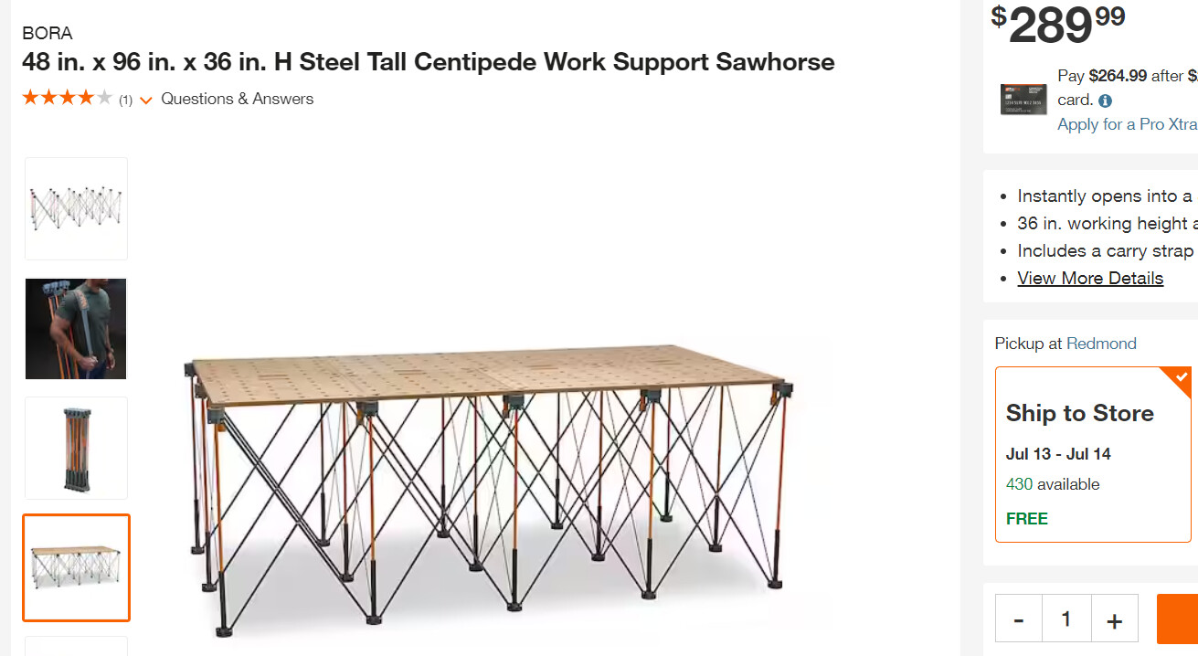
Interesting, they come in various sizes, including 4’ x 8’ !
Not cheap, but looks fast to setup, no idea if they’re rigid enough for the CNC machines we’re using? Concerned all those legs will follow, and project, the contour of my uneven floors to create for an uneven spoilboard.
Now thats a nightmare to level
they’re pretty wobbly.
Here’s a really nice concept for a tilt table - mechanically it’s super - could be done in timber with a lightweight torsion top rather than all that aluminium.
Sorry it’s a 60 second clip because it’s my first attempt at creating a youtube clip (how good is that feature?) and only 45 seconds of actual content!
The foot nearly takes up as much space as the table… ![]()