LR3 traming - X and Y direction

There’s been quite a long discussion yesterday with a few forum members in another thread here: Pocket with a T-slot bit - #23 by Fabien
I’m making a dedicated thread, as I dig deeper into the problem…

Short version: What are the possible ways to tram the LR3 tool in both X and Y direction

For the Y axis (front to back tilt), small shims between the core and the tool mount bracket seem to do the trick
Not ideal, but definitely do-able…

For the X axis (left to right tilt) though, I cannotfigure out a way to adjust.
As explained and pictured in the refrenced post, compensation for the tool tilt through the Z gantry squaring also modifies the final height relative to the surface

I’ve been making some measurements trying to rule out a maximum of errors on my part
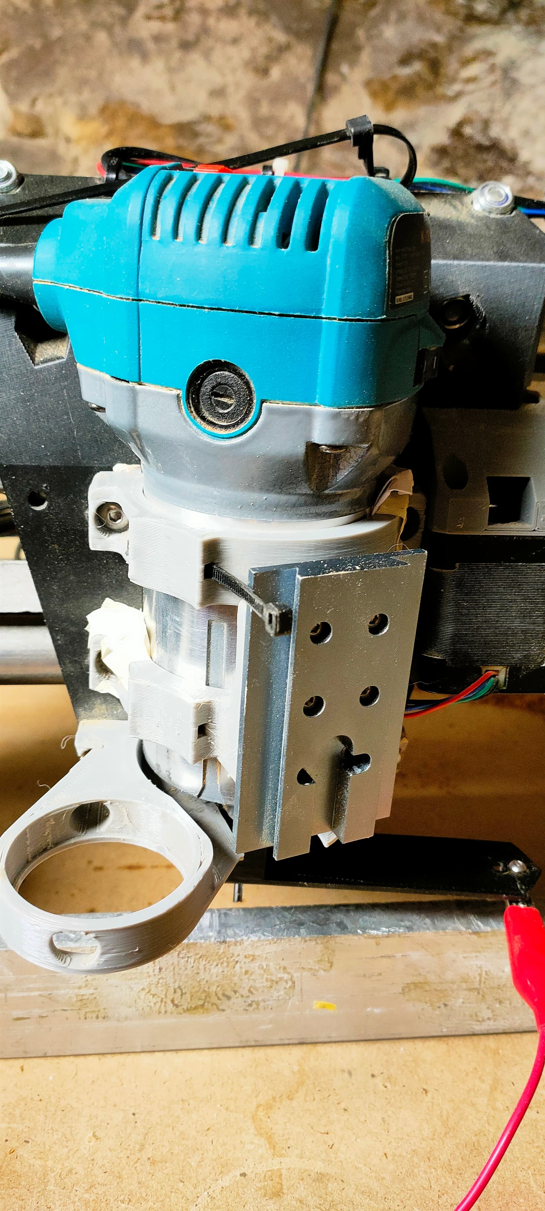
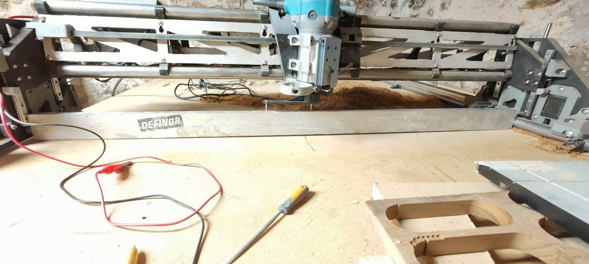
Here’s the setup

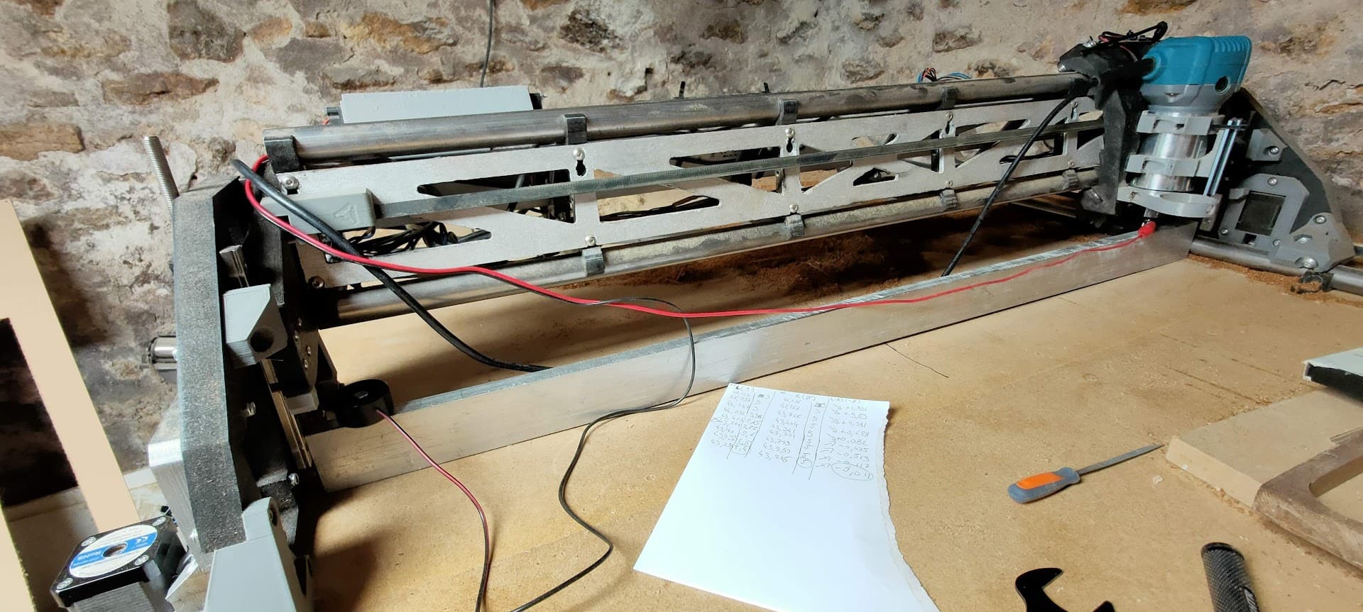
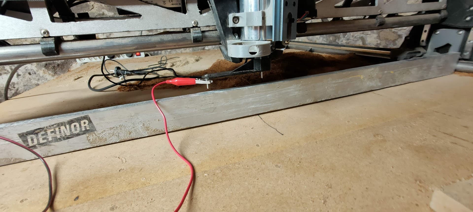
I first installed a straight aluminium ruler through the X axis to eliminate the table’s bow and refrence a straight edge
The probe’s nagtive is connected to the ruler so I can probe the ruler directly using the bit

I leveled the gantry relative to the ruler by adjusting the z motors pulloff_mm param, homing, probing on both ends, adjusting , and repeating the process
Once done, I can run the bit just a hair above the ruler across the whole length with an almost constant space in-between the bit and ruler (maybe .10mm difference over 820mm of travel)

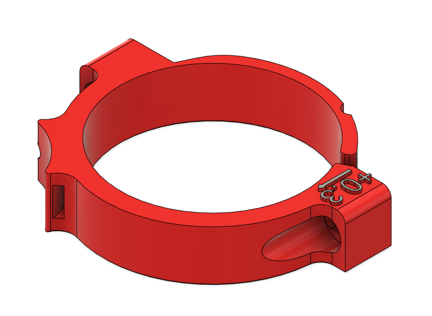
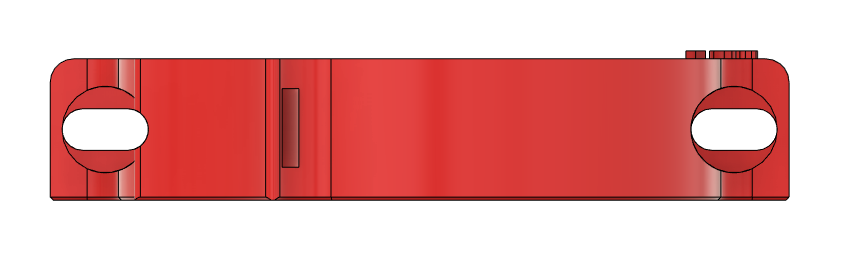
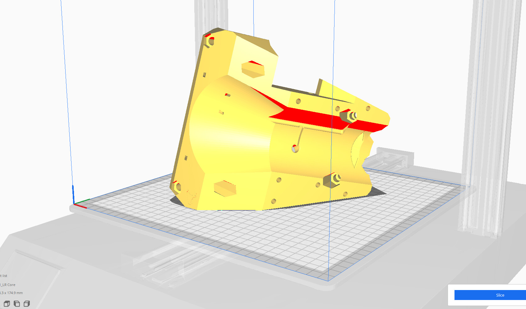
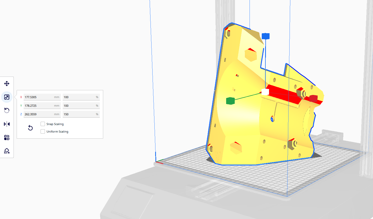
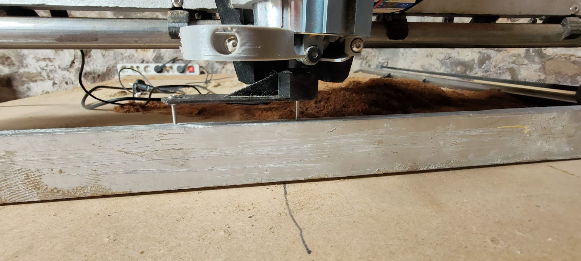
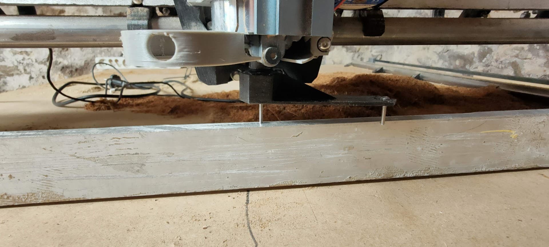
Once done,I installed this printed tool on the collet to visualize and measure the perpendicularity of the router to the ruler.
image

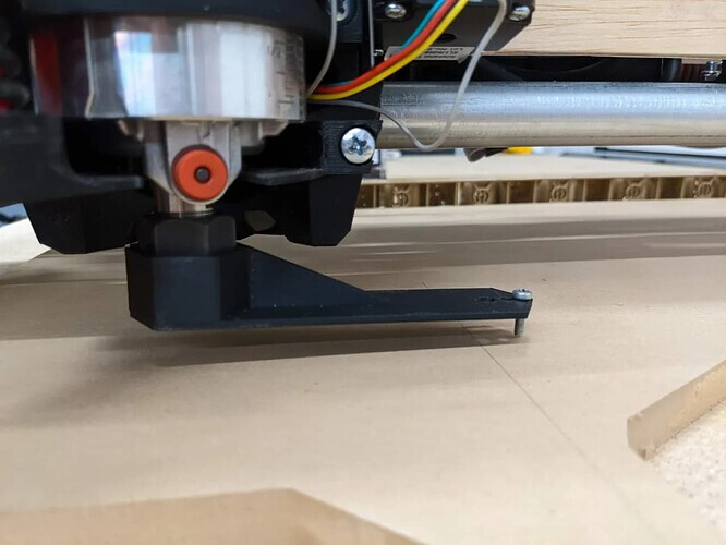
This is measured in the center of the X axis.
Left side:


Right side:

The right side is clearly lower than the other…

Note: I re-checked for sanity, and can confirm the router bit is strictly parrallel tu the ruler’s edge in-between the two points measured by the tramming tool end

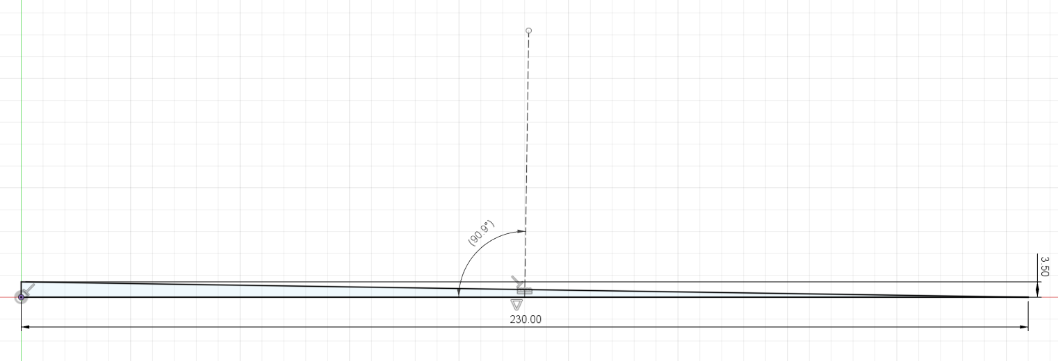
I Installed the probe clamp on the little screw and probed against the ruler on either side, I’m getting a 3.25mm between the sides

Probing with the router at X=50 yields the same results

What could cause this tilt in the X axis? What would you check after this for misalignment?
How would you go about adjusting this?

Left to right was where I had to adjust mine. I loosened the tool mount, Slid the spindle up, Put a single piece of painters tape in the area that needed it and then put the spindle back in the mount and remeasured. It was at .00011 after applying the tape and left it there

So, masking tape wrapped around the top/bottom tool bracket on one side or the other ?

I added pretty thick papier shims (1.0 to 1.5mm thick) on the top and bottom brackets, opposite sides
Also weighted heavily on one side while tightening the bolts…

Gained maybe 0.5mm, but there’s still 3mm more to go… :confused:

Yes that’s all I did. About a 3” piece on the top of my low side. All depends on how far you are off for how much you will need. But start slow.

3" ??? How much is that in metric?!
3 inches is 76mm, seems pretty radical, and I coulent see it fit!

1 Like

I meant the piece of tape I used was around 3” long. Not thick. And that’s just a guess. I didn’t measure it

I assume you are homing the machine at the top and then jogging it to where you are measuring? Have you moved the z axis home switch? I expect that if you were to measure from the table to the switch position you will find the extra space.

Caveat. I have not gotten mine up and running. Just remembered that the limit switches are adjustable. I also feel like you could fix this in software with a limit switch position statement.

Traming is a little different than leveling the X beam. That is done first at the extremes of X to get the limit switches level in software. This is to get the spindle straight with the table. So that when you are surfacing you don’t get gouges and lines.

I understand that. But if the x beam is not level then you will never be able to tram the router. There is not enough adjustment available.

True. I’m assuming he leveled his X beam before trying to tram his router.

That’s a bit like chasing your own tail indeed :slight_smile:
I made a few drawings in the other threads to try and wrap my head around how the order of operation could affect the setup

As you can see, you could surface with the gantry totally skewed from an imaginary horizontal line, or even from the average table’s surface, and still get perfect tramming, as long as the tool is perpendicular to the gantry

On the other hand, as soon as the tool is not perpendicular to the gantry, whatever ation you take, no matter how many surfacing oepration you do, the tool won’t be perpendicular (tramed) to the surface

What about this. Level your X beam. Then surface. Sure your going to end up with ridges because your spindle isn’t tramed. Then take something flat, Piece of aluminum or whatever you have handy that’s wide enough for the swing of your traming tool. It will now be sitting on the ridges of your surfaced table so should be level with the X beam. Then run your tramming operation. After that do just a light surface again. just enough to take out the ridges and your left with a flat spoil board.

1 Like

Yep, but still, adjusting the tilt front to back is pretty easy, but I find side-to-side very hard to adjust…

On this particular notre, as mentionned in the first post, I have 3 to 3.5mm height difference between the two positions of the tramming tool (230mm apart)
And that may be the problem, I shouldn’t have so much tilt…
That’s roughly 1° of tilt of the router side to side

Couldn’t get any shim that fit in betwee the bracket and tool thick enough to compensate for this :confused:

I tried re-printing modified brackets with some slack built-in and see if it’s doing better
I took the occasion to add some other features I needed too anyway, and added a +0.30mm extra on the back of the top bracket to account for my front to back tilt

This looked promising at first, as I could wiggle the router side to side a couple millimeters, but as soon as I tighten the bolts , it just “straightens” itself back in position, and out of perpendicularity :confused:

Ah… at least I have the front to back sorted out, and added a wider hole for re-usable zip ties in the process…

After this miserable failure of trying to fix a perfectly good design, I just thought a bit harder about what could be the cause of the tilt. if it’s not the designer’s fault, maybe it is mine (of course I tend to give credit to this option only after a couple days of bitching and trying to “fix” everything :p)

And maybe I found something…
In my build log, you can see that I had a few issues with the printed YZ plates, that were just a bit too tall and caused binding on the Z leadscrew
This was due to my printer’s Z axis not being calibrated, and it was printing “too tall”

Well… here’s the core in it’s recommanded printing orientation

Let’s say my printer has a tendency to print “too tall”, and exagerate it a bit:

If we turn this around

Well, the model is deformed, and everything but that’s not the point, my printer is not “that badly” calibrated :slight_smile:
The interesting thing though, is that, through the slight angle the core has when printing, the two mounting bracket holes are not horizontal anymore

Could this be an explanation?
I’m not particullary willing to re-print the core just to test that theory :confused:

Any other idea as to why I get this tilt? Or a way to get more adjustment and correct it?

1 Like

3mm seems very excessive. I believe the most I had was less than .5mm and that was over a much larger distance than you are getting with the printed tool. So your theory on the Core being skewed is very plausible to me. But I will let other much smarter than me people chime in on that one lol

2 Likes

What bothers me is that the tilt is in the other direction, so I might be totally wrong here

Do a calibration cube! is your z too tall?? I printed a normal then a 200 % before i printed my core.

200% you can check with a square as well!!

The printer has already been re-calibrated in the meantime
How Can I check directly on the printed core?
It has very few straight edges for reference…

Another question : does the tension on the lower bolts have an influence on the tilt?

I’m just skimming through this so haven’t quite got the lot sorted in my head.

I only ever use three points when I’m plumbing something - like a tripod, The concept of side to side and front to back doesn’t exist.

The penny dropped when I was levelling surveying gear in the olden days.

It’s not going to help if you’ve got so much tilt, but when you get closer, try inserting your shims at about 12, 4 and 8 o’clock. (on the face of the router not at four hourly intervals! Sheesh! :smiley: )