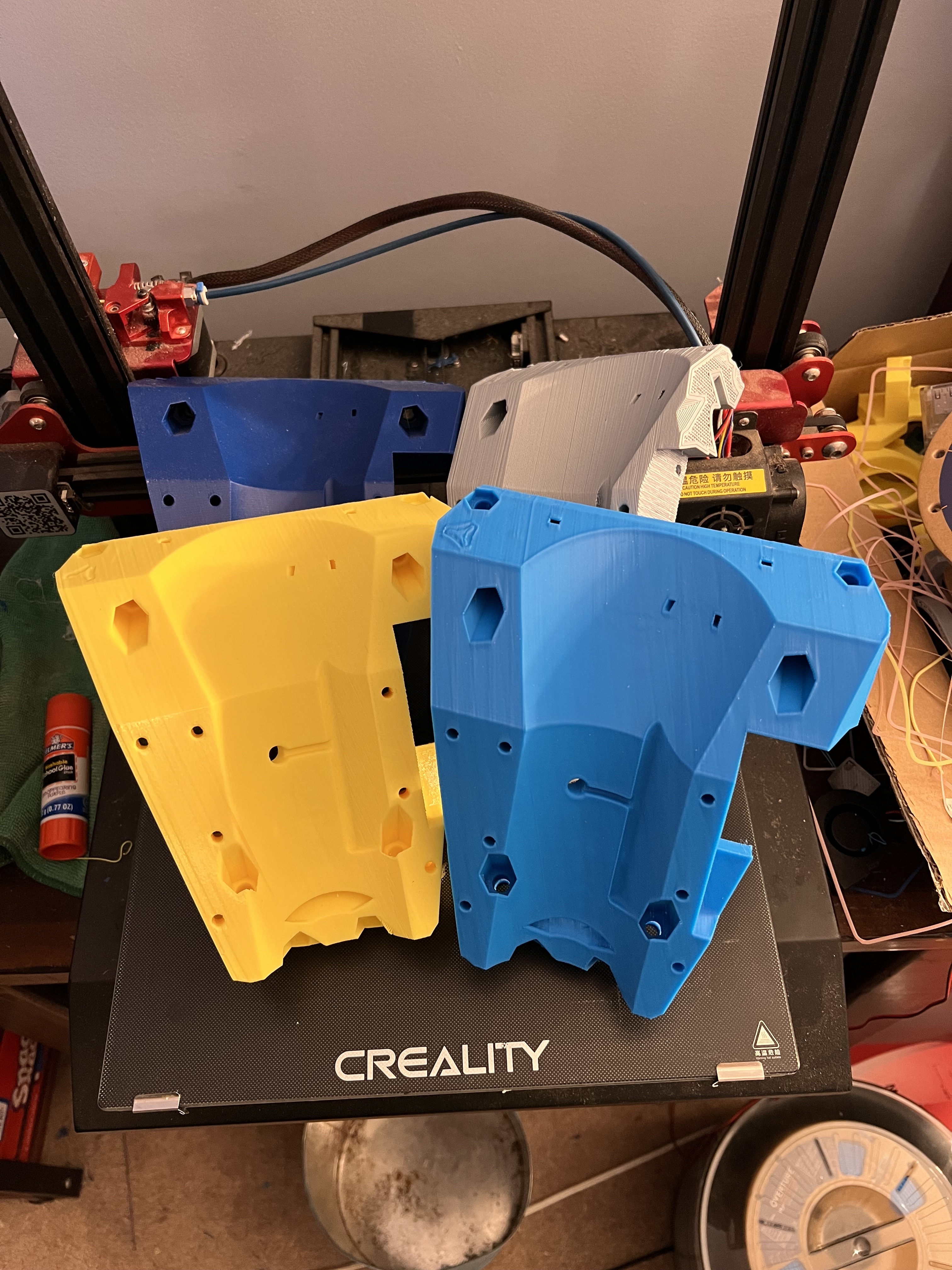
I printed three cores… ![]()
1 Like
Ok… amazon 1 day delivery is definitely useful sometimes…
Just received my digital level I ordered at 11AM (it’s 9PM right now…)
Much easier to measure and see what’s going on…
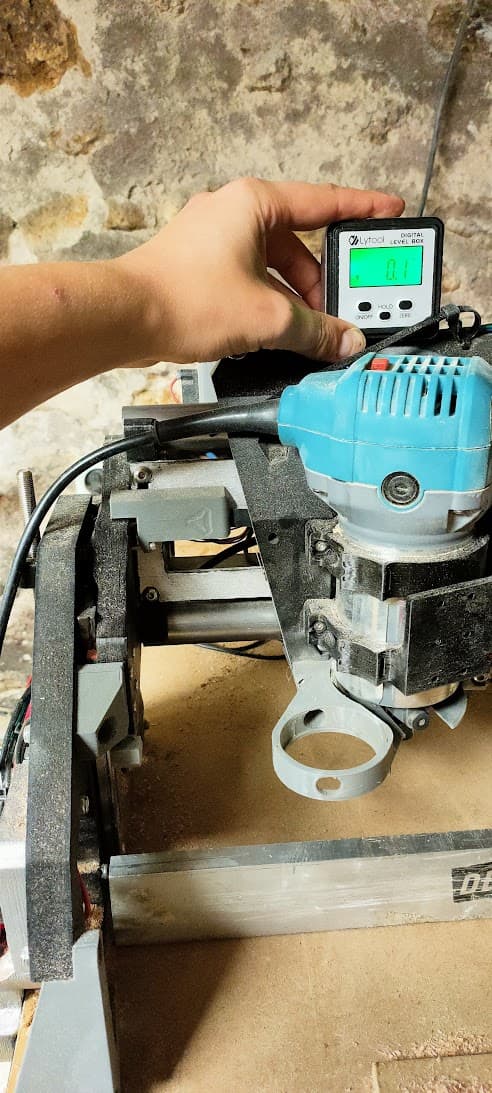
Put the level on the gantry and zero’ed it (btw in absolute mode it’s leaned 0.1° to the horizon…)
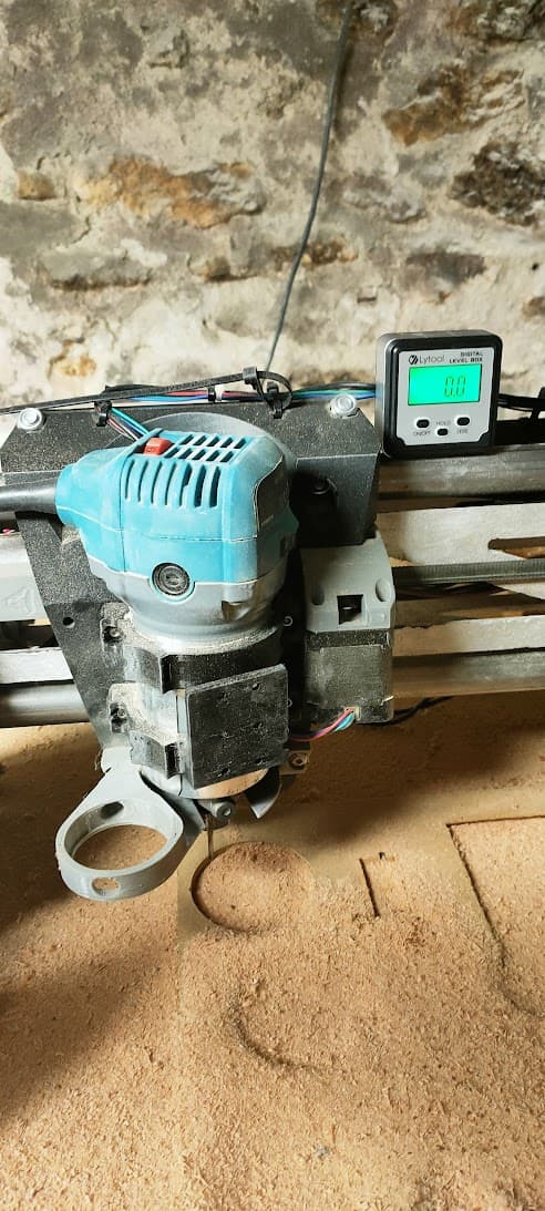
Then on the side of the mount (made contact with the small stub on the side of the brackets where the screw go in)

This should read 90° relative to the gantry, it reads 88.9°, so that’s 1.1° off, pretty much what I measured with the traming tool
Now I need to find why this is crooked…
Either I reprint a core overnight, or I try to remix and print customized brackets accounting for the tilt now that I know how much it is
Advice?
3 Likes
I’d just ignore it. You won’t notice it on any cut, it’s just to maybe feel better. ![]() My Z has got a difference of 0.42mm on the whole 1220 width. I could install a new firmware that allows me to use offsets in the software like you guys can, but I calculated that it is 0.00034mm height difference per mm, so around 0.137mm when planing a 400mm cutting board and I can absolutely live with that. At least until I installed the new firmware…
My Z has got a difference of 0.42mm on the whole 1220 width. I could install a new firmware that allows me to use offsets in the software like you guys can, but I calculated that it is 0.00034mm height difference per mm, so around 0.137mm when planing a 400mm cutting board and I can absolutely live with that. At least until I installed the new firmware… ![]()
What I cannot live with are things that visibly affect the cuts/inlays. ![]()
1 Like
This is not the height of the gantry relative to the work surface, it’s the perpendicularity of the tool relative to the gantry, and therefore its perpendicularity to the work surface
And that’s indeed noticeable, at least with the amount I currently get…
When surfacing, I get those wavy lines along the surface
And that’s just with a 3mm bit…
If I try to use wider surfacing bits like a 12/15mm one, this get even worse…

Moreover, I get a slight skew on the walls too
The walls that are supposed to be perpedicular to a surface are in fact 89 or 91°
It may not be that important on some pieces, but as soon as precision is important, or you need the part to fit witihin another, this get quite noticeable
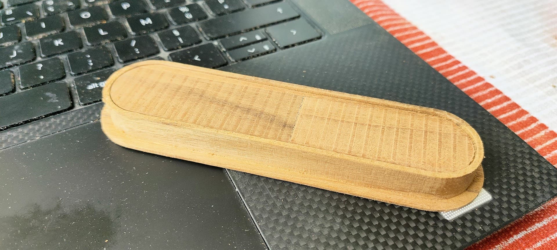
eg: when I made the routing jig for my door handles, the router definitely eated at the template because of this slight skew
1 Like
For X I agree, it should be perpendicular, it’s pretty easy to achieve with a shim. I have never noticed on Y though because all the pockets are cut left to right, so following the X-axis’ skew. Those lines in the first picture are really quite noticeable, the lines in the second are hard to judge. I also see lines when planing on X because of minimal burning of the walnut, but I can’t feel them, it’s just a slight discoloration. Can you feel those lines?
Yep, definitly noticeable and you cnan feel it
My specific build has quite a severe tilt though, and I cannot fit enough shims to correct it ![]()
Maybe you should really try with a new core. ![]() Jon and I already showed our failures.
Jon and I already showed our failures. ![]()
2 Likes
That much deflection can probably be fixed with a piece of masking tape in the tool mount. Maybe one on the top and one on the bottom (opposite sides)
I would also most definitely check the whole X/Y plane, since you will also get artifacts where the bit goes across as well. That wont adjust the plastic that the tool sits in, but it will affect the router.
On my Primo, I.was getting a similar issue, and fixed it by tightening one top tool mount screw (to the Z tubes) about a half turn. The equivalent would be the mount ring to LR core screw.
Sadly, no… already tried…
Not sure I’m getting which parts you’re talking about?
Is this the tightening bolt on the bottom?

Do you mean “Are the YZ plate and XZ palte perpendicular to the gantry?”
Here’s the whole measurment the arrows indicates if the left side should go up or down to be level)
Zero-ing on the gantry first
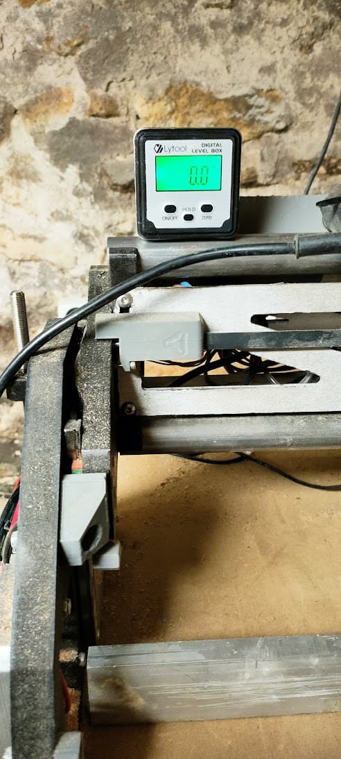
Relative to the table (averaged with a ruler across the X length)
Not that it matters much for traming anyway…

Relative to the top of the LR core → 0.1° - Down
Relative to the tool brackets → 89° - Up :
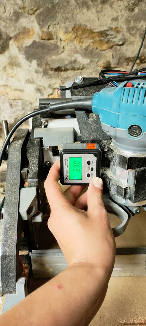
This correlates exactly with the measurement of 3mm between sides I made with the traming gauge
Relative to YZ plate → 90.5° - Down
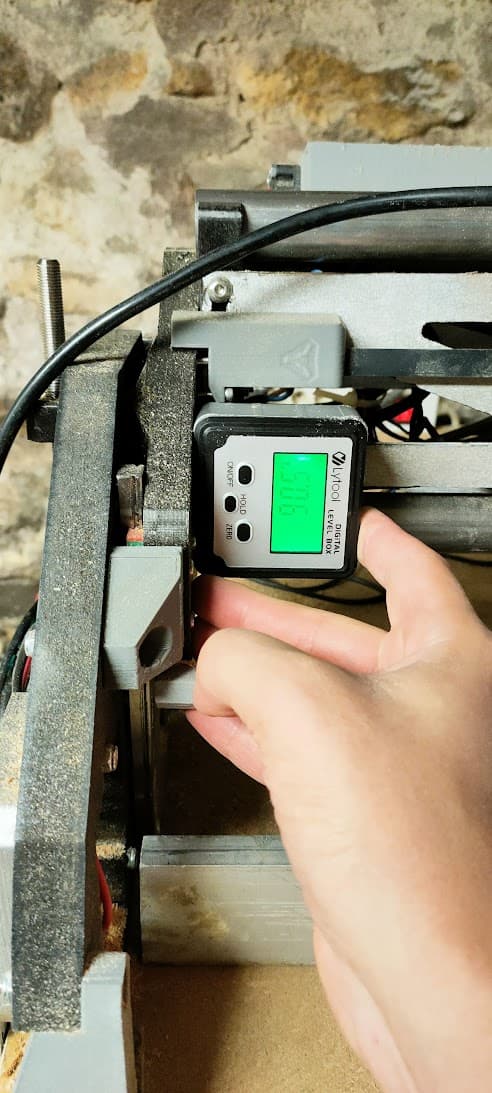
I don’t really know why it wouldn’t be perfectly perpendicular, but in my comprehension, this shouldn’t matter much , it just means the rollers have a bit of inward camber (LR3 “Tokyo drift edition”) and I need to compensate a bit with the Z height on this motor
2 Likes
OK, if you haven’t already started the big print…
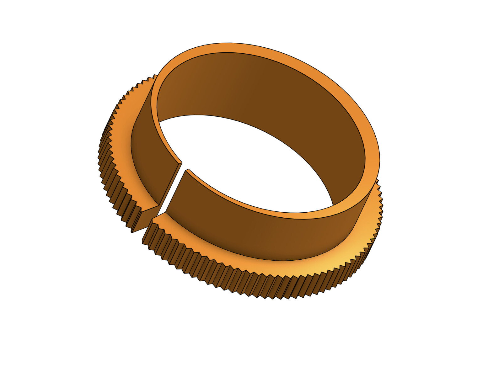
If you print the tool mounts with the router diameter about three mm oversized, you could then print two concentric inserts with an offset centre the correct size - to give roughly 1.6mm of offset on one side compared to the other.
Insert one in the top mount and one in the bottom mount and simply rotate them until the router is perfectly trammed.
Should I patent this idea, or just let you see if it works before I get too excited? ![]()

If it works I’d put a little 45 degree flange on the “inside” edge and a matching one on the tool mount to make it captive.
5 Likes
No, and I’m glad I did not ![]()
Made 2 calibration cubes, and had a regret before firing the print for the core…
I instead printed a custom top bracket with the inner circle slightly offset
Printed but not tested

But… This Idea with the cam-circle… This is genius sir! ![]()
I will definitely try this
1 Like
I’m pretty sure it will work with a much less pronounced cam, of course it might take a bit of a knack to get it right, and you’d have to start off with the cams exactly the same orientation or there would be a whole new world of hurt! ![]()
Yep… I was thinking about parking the outside of the ring si that you know how much and where it’s compensation…
I need to wrap my mind around this and see what it can or can’t do, but the Idea is very elegant and clever
I’m giving this cam thing a good thinking…
With this setup, you can only adjust the direction of the compensation right?
This direction can be adjusted continuously
But the amount of compensation (how far back you force it to tilt) is fixed, right?
It’s equal to the cam offset you designed it with (eg .8mm)
Wouldn’t that be a problem because if you don’t have the right offset you’d continuously over/undershoot, whatever the direction?
You’d need to test and reprint with différent offsets until you get it right (or mesure the tilt and make a calculation if the offset beforehand)
No, the offset is infinite and in every direction - if you start with both cams in the same spot, you have zero offset. To adjust turn in opposite directions, to adjust the axis of the adjustment, turn in the same direction and repeat.
The maximum offset in the above diagram is stupid large (2.2mm top and bottom which totals 4.4mm!)
If I wasn’t so snowed under doing absolutely nothing waiting for prints, I’d mock one up to demonstrate.
1 Like
I’m still thinking in separate X and Y adjustment (I know, I know… this is wrong…) that’s probably why I have a hard time figuring out this ![]()
2 Likes
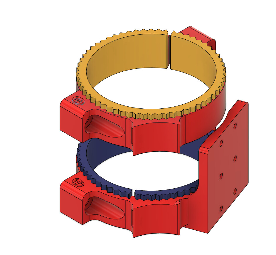
This is what I come up with following your idea
(I marked the brackets with a logo so I don’t mix them up with the original ones :p)
Printing the first bracket right now…
2 Likes
You can think of it as needing an offset in X and an offset in Y. Those offsets add up to a vector (X, Y). The vector has a magnitude (length (sqrt(xx+yy))) and direction (tan(y/x)). You can rotate both rings to change direction. And then rotate them relative to each other to adjust the magnitude (length).
It’s a bit like corexy. Very creative. Very useful. Very unintuitive.
You need to start with a very good measurement of XY needs without any adjustment. Write it down. After adjusting the rings, measure them again and subtract the original measurement on paper. That difference is what you can control. You can use that to see if your direction is right or your magnitude is right. You can’t tell from just a single measurement.
It may be possible to just adjust it with the measurement tool installed. Our brains are amazing calculators. But I know from experience that if you want to measure it, use paper (or a spreadsheet)
1 Like
![]()
![]()
1 Like