I´ve got camber on mine too. I suspect it is a combination of factors (bearings, table, lightly crooked sidings,…).
That will depend on what you are doing. I´ve made some parts in the past I glued together (3 the same pieces of 18mm) and the tilt becomes obviously then.
Myself I was reading this one from shapeoko link. Pretty interesting and some parts will be true too for the LR3. It basicly says what you are soing too with your drawings
wonderfull! Maybe it would be good idea to add a mark to the router holders? So you could call it “0”. That way you could count the notches instead of guessing how far you´ve turned it around? Similar like how one does it on snowboard bindings to know your feet angle?
just an idea: couldn´t you open up the holes with a drill to have some wiggle room whil tightening the screws?
I re-printed a bracket with elongated holes, this all works as long as you don’t tighten it
As soon as I tighten the bolts, it resets to it’s initial position
I think it’s the back of the bracket that centers itself into the core due to it’s shape
This would probably work if I found a way to force it out of alignement while tightening it, but that’s very sketchy…
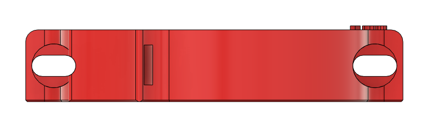
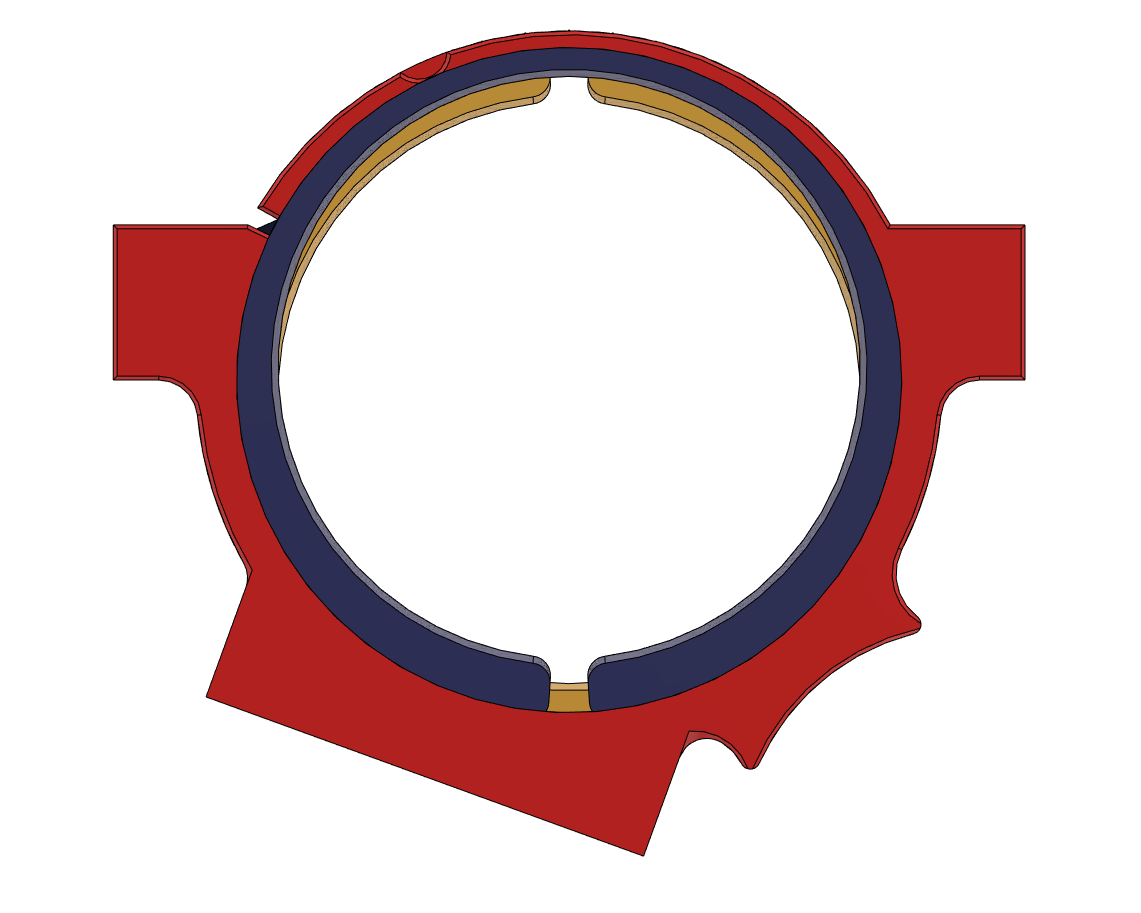
On the “cam adjust” thing side, I just realized I made a design error on the rings, and need to reprint them >_<
For illustration purposes, here’s what it looks like
No not the ones you indicated. The M5 screws that hold the tool mount to the core. I was able to get enough movement to tram my router adjusting those without overtightening. Some of my problem was the torque on those screws was a little inconsistent.
The offset ring solution is excellent and looks like it will solve your tramming issues.
If you’re going to chase zeros, chase the right zeros! You’re checking that the bracket is perpendicular to the gantry?!? That means diddly-squat. I mean, sure, it helps a bit, but the real culprit is the actual spindle core, i.e., the axis on which the bit spins. Which may include some amount of runout. You actually need to get a length of 1/8" or 1/4" rod (or whatever will fit your collet, and allow you to measure w/ your digital level), and chuck it up, then test that for perpendicularity to the gantry. And then rotate the “bit” to see what sorts of runout you have.
Well I’m chasing a bit more than zeros here above one whole degree in fact
But yeah, you’re right , this should be the right way to measure, although, really, measuring at the collet should get me right in the ballpark at least (not trying to get an absolute perfect traming, just a usable setup with reasonably sized bits)
To give you an idea, that’s already 0.21mm between edges for a 16mm wide surfacing bit, 0.1mm ona 8mm bit…
So, yeah, not very noticeable on a 3mm bit when surfacing (but who would do that?), but as soon as you get past 6mm wide bits, it gets very noticeable
Also, even witha 3mm bit, the walls turn out slanted, thats 0.23mm difference in the X axis between the top and bototm on a 18mm (3/4") thick stock
Ouch. That sucks. But in a way I think its a good thing. You know your printer was off and wasn’t fixed until after you printed the core. I’ll be very curious to see what your measurements are after you reprint and try to tram.
One degree is about 0.02 rad. Small angles are about the same as tan(angle). So for every 100 mm between the two tool mounts, you need a 2mm correction. That seems like a reasonable approximation given the accuracies of the measurements and models.
That seems pretty high. I would have expected near zero in that direction. What is it in the other direction?
Indeed, that’s a very high tilt, that’s exactly why I keep repeating those numbers
In the “Y” axis (sorry Peter! :p) it’s pretty much inexistant, just a small paper shim added behong the top bracket corrected it
But it’s a bit hard to check because my table is slanted in the Y axis and I need to surface it (and that’s why i’m tring to fix the “X” tilt first)
That’s part of the reason behind this thread too.
It’s about fixing my issue, but also about documenting how we can measure and fix the issue
Hope this can help someone down the road…
1.5 hour into the LR core print… 12 more to go …
this should print overnight if there’s no issue with the filament roll
You’re excused, that’s a pretty long post
That was one of the possibilities, see here: LR3 traming - X and Y direction - #15 by Fabien
but I wanted to try and diagnose further before comitting to re-print such a big part
Turns out the core cracked at some point when fiddling with it (or was it cracked beforehand?), so, re-print it is…
I found a very attractive price for a locally produced pack of 10kg of PLA…
Turns out that was not 10x 1kg as I expected… just one big 10kg roll! >_<
Now I’m slowly re-spooling it on empty spools until it’s light enough to be usable as-is…
I made a large spool holder with bearings and all (laser cut on the LR3) but it’s still too heavy…
@Fabien If you are going ahead with the cam gadget (and someone should ) you will find a triangular tramming tool much easier to get your head around where the thing is because it gives you a visual connection with three planes at once.
The router will appear to be moving in all three dimensions concurrently and as you rightly said you can only see two of them at a time.
This gadget will invoke the levelling Ninjas. (you need to provide a bolt to insert into the collet) It will allow you to see what is actually happening and you should be able to just very accurately once you get a feel for it.
I have been going to make one for some time, but never had the need for more accuracy than the LR2 gave me!
I don’t share things on Printables I haven’t printed and used, but on V1e anything goes! I’ll see if I can get it uploaded here tonight, otherwise it will be Tuesday next week I think (Monday for you!)
You blokes have caught me out a bit, I did a quick sketch to illustrate a concept and now look what’s happened! Here’s a version that’s a bit better than a sketch!
A few things to note - the centre hole is currently 1/4" - if you get a long bolt, cut off the head and use a nut each side with a washer it should be quite rigid - overall the arms are about 90mm each and 8mm deep ribs and they shouldn’t be under load.
The “points” were a bit of a concern so I flattened them to give us a hope of printing them at a consistent height - maybe a careful measure of each one on completion and a gentle rub with fine sandpaper to clean off any filament dribble will help. I can’t think of a simple way of getting this repeatable, but the idea is to use it to get close to where you want to be (when using the offset cam levellers).
Who knows, with so many test pilots we might come up with something useful! I’d print in PLA and I’d be inclined to use 4 or even 5 perimeters so that those ribs and the core bit remain really rigid.