Skew Correction

Hey all,

After reading about @Fabien’s challenges to correct for non-perpendicular core (LR3 traming - X and Y direction), I decided to check my printer for skew before attempting to print the core for my upcoming build.

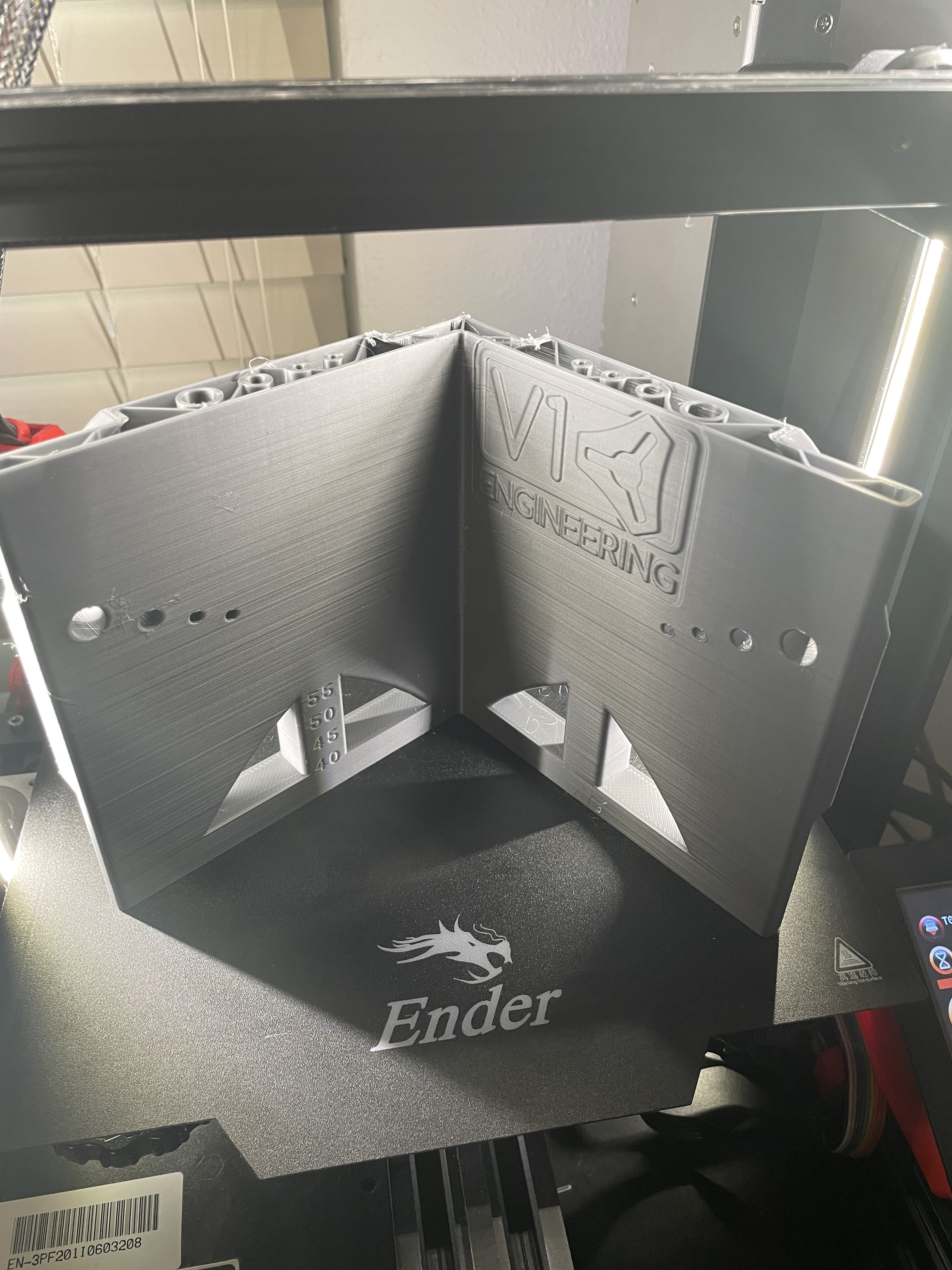
I printed Ryan’s (@vicious1) xzyz-test file from Printables (15.4 hours, almost 150g of filament at 5% grid infill). I did have to rotate the print to avoid one area of the bed that was having some adhesion issues (warped glass bed?), so the X and Y labels were swapped, in case anyone notices that.

I’m not sure exactly how to interpret the results.

X horiz = 140.89
X vert = 139.85
X \ = 150.10
X / = 150.63

Y horiz = 139.88
Y vert = 139.89
Y \ = 149.56
Y / = 150.20

Using a square, I get pretty close to perfect on the XY and XZ section

When measuring YZ using the bottom layer, I get a bit of visible gap

When measuring YZ using the top layer I get a much more noticeable gap,

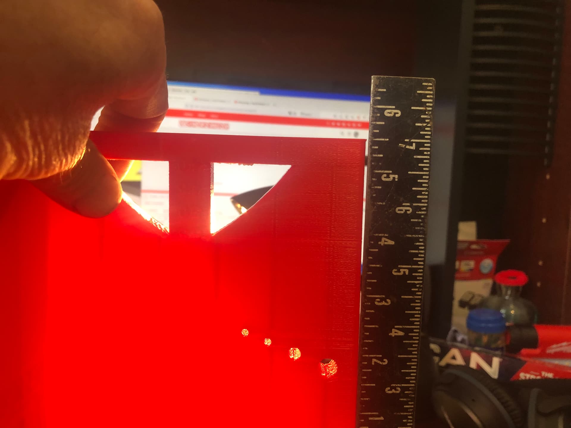
but when taking the same measurement using just the top of the thickest section (rather than the entire length of the narrow section), the results seem much better

I have tightened up all of the screws on the printer prior to printing this piece. and don’t see any obvious bent or misaligned parts.

So I have two questions:

  1. Are these results good enough that I can print the core as is? ( I hope so, because the next question opens up a can of worms…)

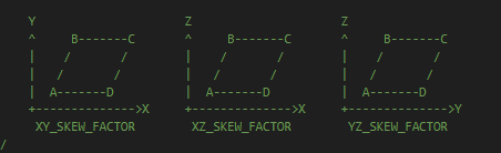
  2. If I do need to make adjustments using the Marlin Bed Skew Compensation (may require re-flashing the printer in order to enable BSC), how do I apply these results to the Marlin Bed Skew Compensation formula?

Marlin configuration seems to be based on a test print that is 100x100, resulting in an expected measurement of 141.421356 mm (doubled to 282.842712 mm), so presumably I could scale these values of the 150 expected test print value (measured value x 141.421…/150 = new Marlin value).

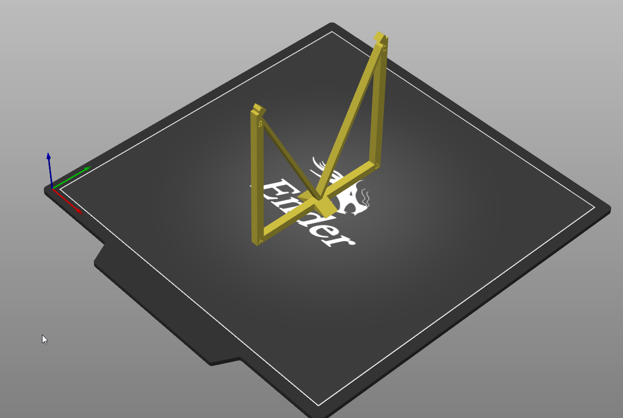
But I am uncertain which points on the test print correspond to AC and BD on the Y axis. Note that the print was oriented so that X axis section was at the back (or Y min) of the bed, and Y axis section was at the left (X min) of the bed. So in Marlin , is the bottom rear to top front AC, or is the top rear to bottom front AC?

Just a note that the LR3 will probably be used mostly for cutting 3’4" plywood, 1/4" aluminum, and possibly carving wood/plywood for signs and decorative items, so I’m not sure how much time and effort I should expend to chase exact square/perpendicular, and if compensating with shims between the core and router might be a better way to skin this particular cat.

Most of the discussion about square/perpendicular seems to come up during surfacing, so if I keep any surfacing tools small diameter, maybe I can live with this imperfection?

Any advice is much appreciated, as always.

I don’t have any advice on whether your machine is good enough for the LR3 parts, but my advice on Bed Skew Compensation would be that if you intend on using it, use the print they intend for you to use in order to get the numbers correct.

Side note…. I set out on the same path as you last night…

Good news:


My Y is dead on.

Bad News: I need a filament runout sensor…

@Michael_Melancon , I have previously printed that cube, with fairly similar results. But the instructions are unclear (at least to me) as to which direction is AC and which is BD.

The square in the link has letters on the face as it corresponds to the instructions in Marlin code.
image

So you’d print the square as oriented, then measure corner to corner like this:

then for the AD side, you’d want to measure across the width just above the triangles at the corners

1 Like

The XY I have figured out, it’s the YZ that is unclear whether to look at it from the left or right, because you have to rotate the file from XZ, and it doesn’t say to rotate CW or CCW

For YZ, you’d want the vertical model from that link oriented YZ like this:

I think you always want the A corner towards the front

He goes through it in detail here:

3 Likes

Thanks @Michael_Melancon , that answers question #2 perfectly!

I’m not going to tag it as a solution just yet, as I’m still hoping to get an answer to Question #1, but once that happens, I’ll tag it for sure!

1 Like

Yes, probably.

That means your entire Y plane is leaning. Not sure what way you actually printed it but the core is forgiving. If you can tilt your Y axis to get it closer that would be cool.

Those numbers are not bad at all, seems like the square should not have had a gap, maybe it was elephant’s foot or something that makes it not sit well in your square. I would think the numbers would show that kind of tilt. Most of my parts do not rely on the surface to do anything important. So I am confident your parts will be good.

2 Likes

Whew, thanks for that! I really wasn’t looking forward to modifying the Marlin configuration.h file, re-flashing the printer, then re-printing a test piece (possibly several times for each step).

Is there a way to tag two different posts as Solution? You answered Question 1, and @Michael_Melancon answered Question 2, so it would be nice to be able to recognize both responses as solutions.

2 Likes

Nope just one. Question 2 was a better answer, question was an educated guess :grin:.

2 Likes

Well if anyone is in a position to offer an educated guess, I would think that you would be at the top of the list!

2 Likes

Be careful of your square too. A lot of squares are not square. If you have a really straight line (like the factory edge on a sheet of mdf), you can make a line perpendicular to that edge, and flip the square to check the line is still square.

5 Likes