I you really want it perfectly trammed, you want your spindle and bit to be perfectly perpendicular to X -Gantry plane of travel.
You want that plane of travel, as a starting point, to be as close as possible to the plane of your table, which can be adjusted according to LowRider CNC V3 - V1 Engineering Documentation
There’s a thread related to this here: LR3 traming - X and Y direction which got spun off from Pocket with a T-slot bit - #34 if you want to do some light reading on the subject ![]()
If your tool is perfectly perpendicular to the table, surfacing should come out correct. Leveling the gantry and the table as close as possible should minimize the amount of material needs to be removed on the first surfacing job.
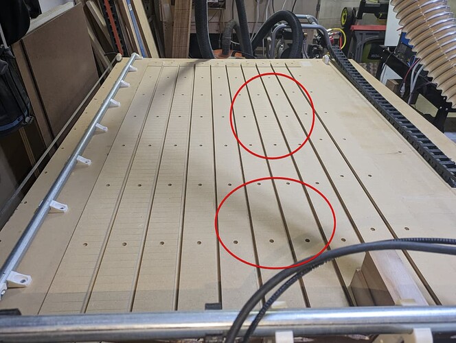
Edit: Looking back at your picture, it looks like I can see lines in your surfacing job on the right in some spots too:
you say it’s “trammed on one side”, but are you sure the tool was contacting the table at those points? Maybe the spots where you don’t see the lines is just where the tool didn’t contact the spoilboard?
Otherwise, the spots where there are lines being mixed like that leads me to believe that maybe your core has some movement in it or something where it’s not consistently making contact everywhere, or your table has some weird plane where it’s causing different angle of contact in other places.
If you want those lines to go away on a wide bit like that, though, I would start with making sure the tool is perfectly perpendicular to the X Gantry.
Others will likely follow along to tell you why it’s probably not that important for most things, like smaller bits, so you don’t necessarily need to chase that unless it matters for your project types, or your OCD ![]()
