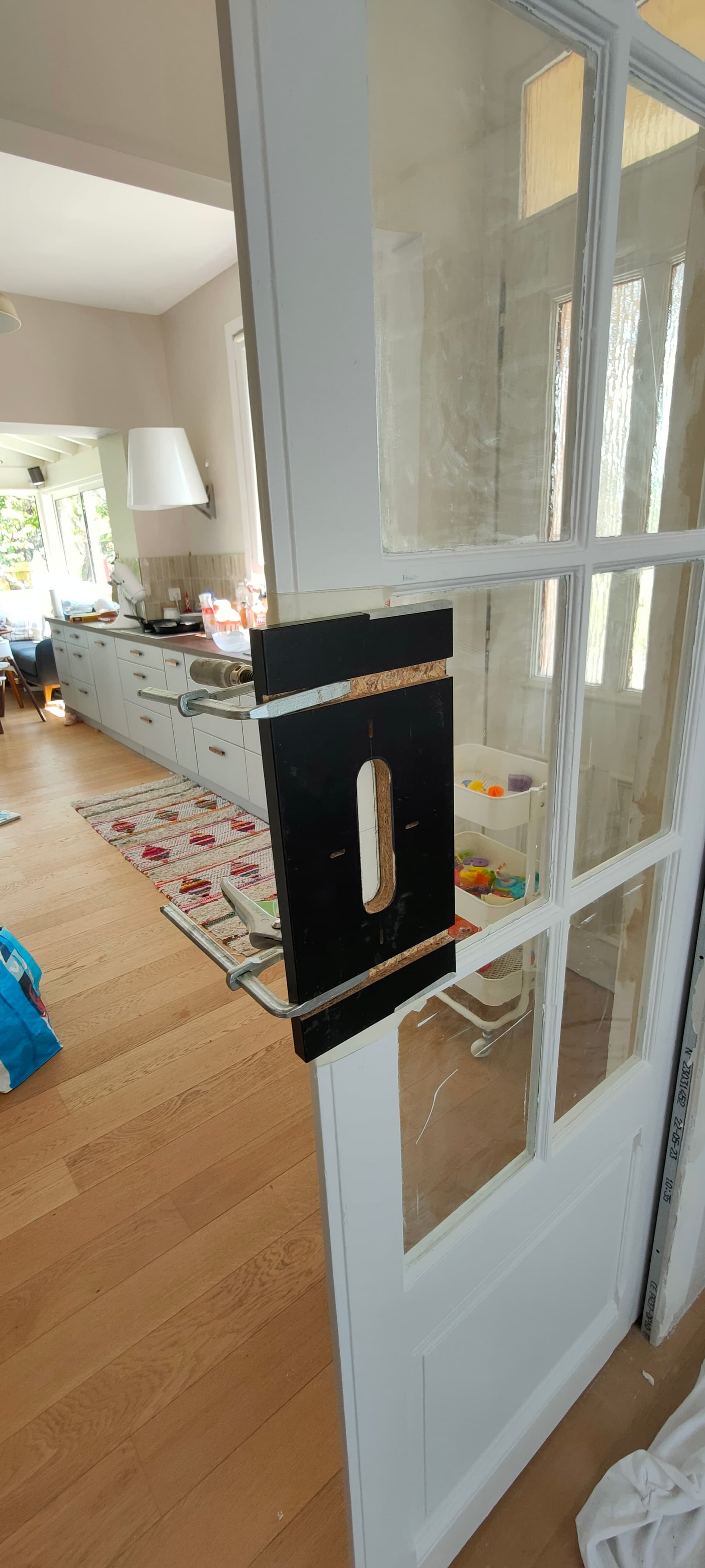
Stressful cuts ![]()
My hands are not as steady as the lr3 ![]()

9 Likes
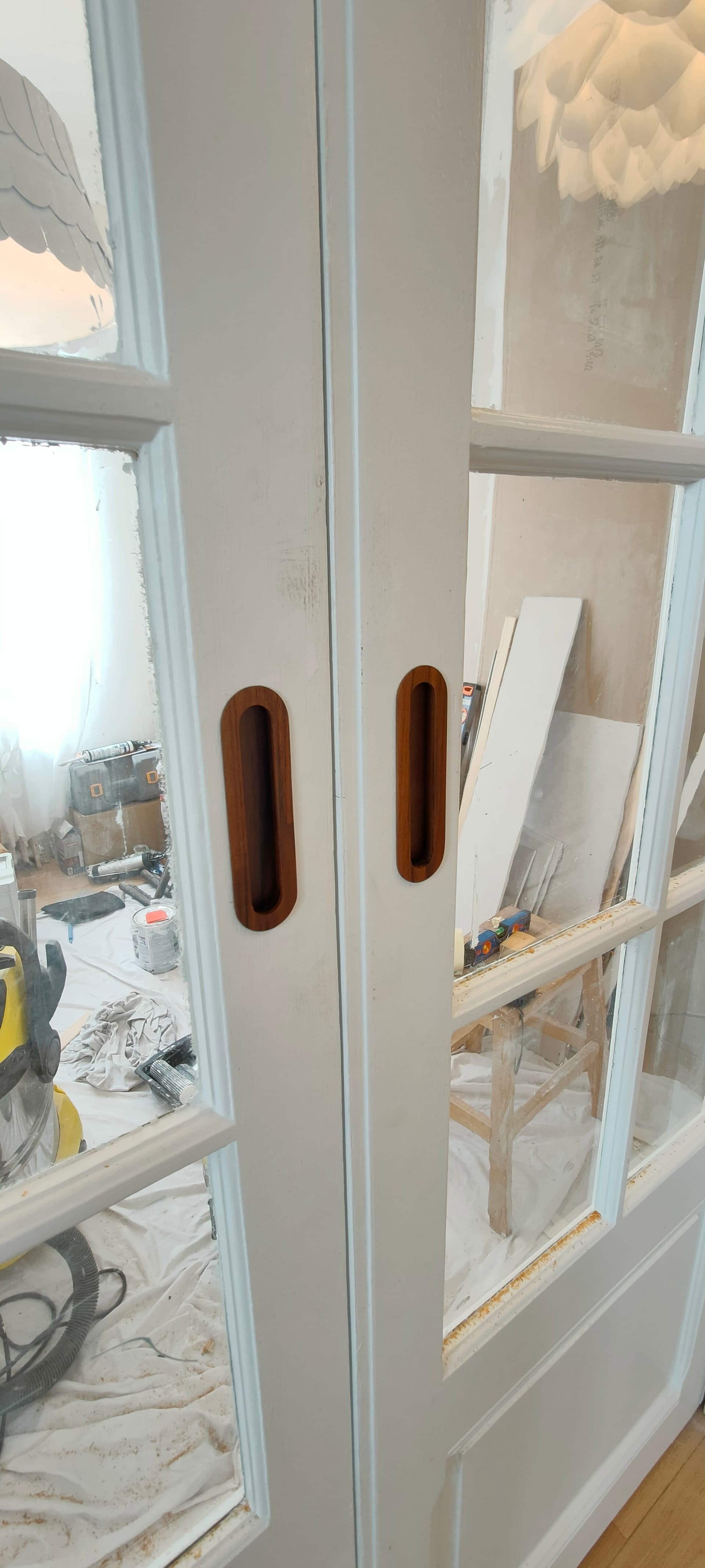
It looks great!
The flange covers all “wiggles”.
Mike
3 Likes
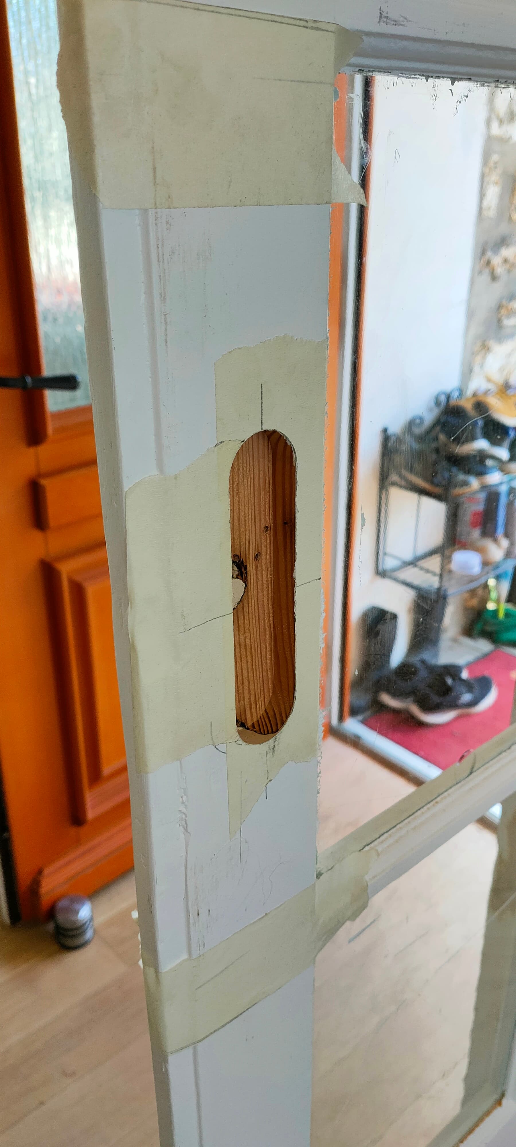
Yes the stripes are from the surfacing operation
I think I need to tram the router but I don’t really know how?
Anyway that’s not very problematic because it’s the black side of the handle ![]()
1 Like
Try this for traming. It worked really well for me.
1 Like
Missing a link?
I’ve seen some 3d printed “bits” that help with vizualizing the amount of skew, but what I mean is: how do you adjust for tramming on the LR3?
Shims behind the tool mounts ?
1 Like
well crap…
I will edit above post
The way I did it I was able to use the touch probe to measure. Once I figured out which way it needed to move I pulled out the Spindle and put a single piece of tape on the low side and that was all I needed. After doing that I surfaced my whole top with an 1 1/4 surfacing bit and you could barely see the lines
3 Likes
I Think I’ll print this one Printables
and use the probe on the screw like you did ![]()
I really wish there was a tramming adjustment built into the LR3 core though… adjusting this seems a bit sketchy…
If I can measure the deviation, maybe I can re-print customized brackets to account for it?
Another question: when I measure the distance between the arm extremity and table, how do I know it’s not the table leaning on one side?
Wouldn’t it be better to use a digital level?
2 Likes
No.
Well, If you do a true level on the table first, then maybe it works. My floor in my shop space isn’t quite level, so my table isn’t level.
What matters is the movement of the tool. The LR mechanism will move the tool in the XY plane repeatably, whether that plane is level or not. The spoilboard should be parallel to that plane. If the spoilboard is not parallel, that could be that the Z screws are not levelled, for example, then this is a problem. It is best to get this as close as possible before starting. Ideally you surface the spoilboard, or a piece of scrap that you will use for tramming. Even if it has “steps” it will still average out as parallel to the XY plane. Then you can use it as a reference for tramming.
3 Likes
Yeah, maybe I should surface a small piece of mdf to serve as reference for this calibration, not a bad idea…

4 Likes
Think of it like leveling a 3d printer. You aren’t trying to make it “level” you are trying to make it match your bed or in this case spoil board. I think the way you are going with the printed part and using the screw is just as good if not better than what I did with the wire. You could go though the hassle of printing new mounts. or you might just be able to tighten yours up a touch on the right screw and get it there. For me I saw no problem with the tape on the spindle. Cant even see it now.
1 Like
Tramming → getting your spindle perpendicular to your work surface.
Leveling → getting your work surface level to the ground.
For an extreme example of the difference, look at a Maslow design…
Getting your spindle perpendicular to the ground is useless, unless your work surface is also perfectly parallel to the ground. It’s all relative frames of reference. You want the spindle square in reference to the work surface.
1 Like
Yes, that’s why I was talking about a digital level, not a physical one
If I zero the level on the table, I’m looking for 90° on the router bit
With this setup , the table being parallel to the horizon or not does not interfere
Anyway, I spent some time trying to level and tram the machine
As I suspected, the table has a noticeable bow in the middle, so neither of those operations was easy…
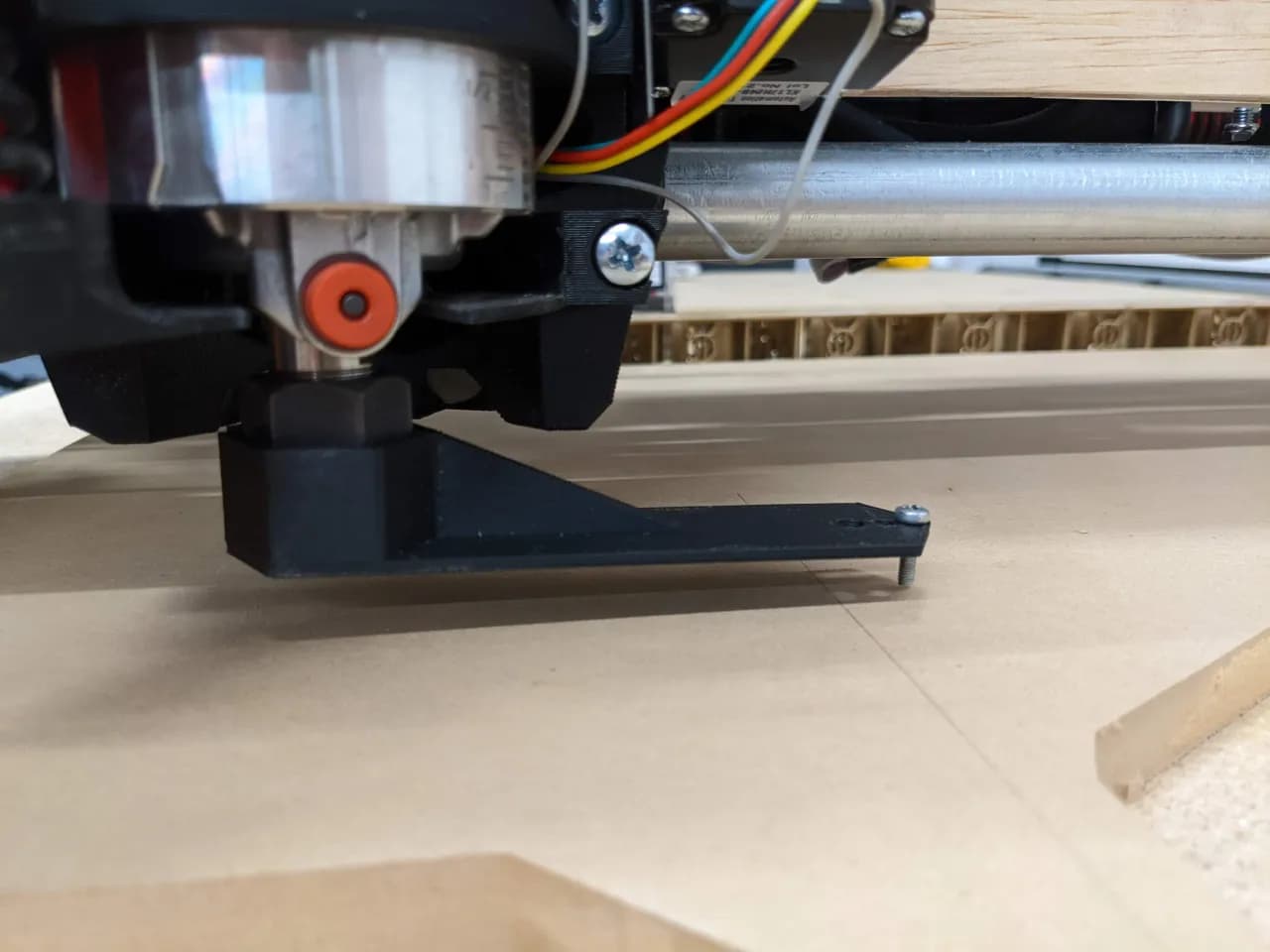
I came up with this setup
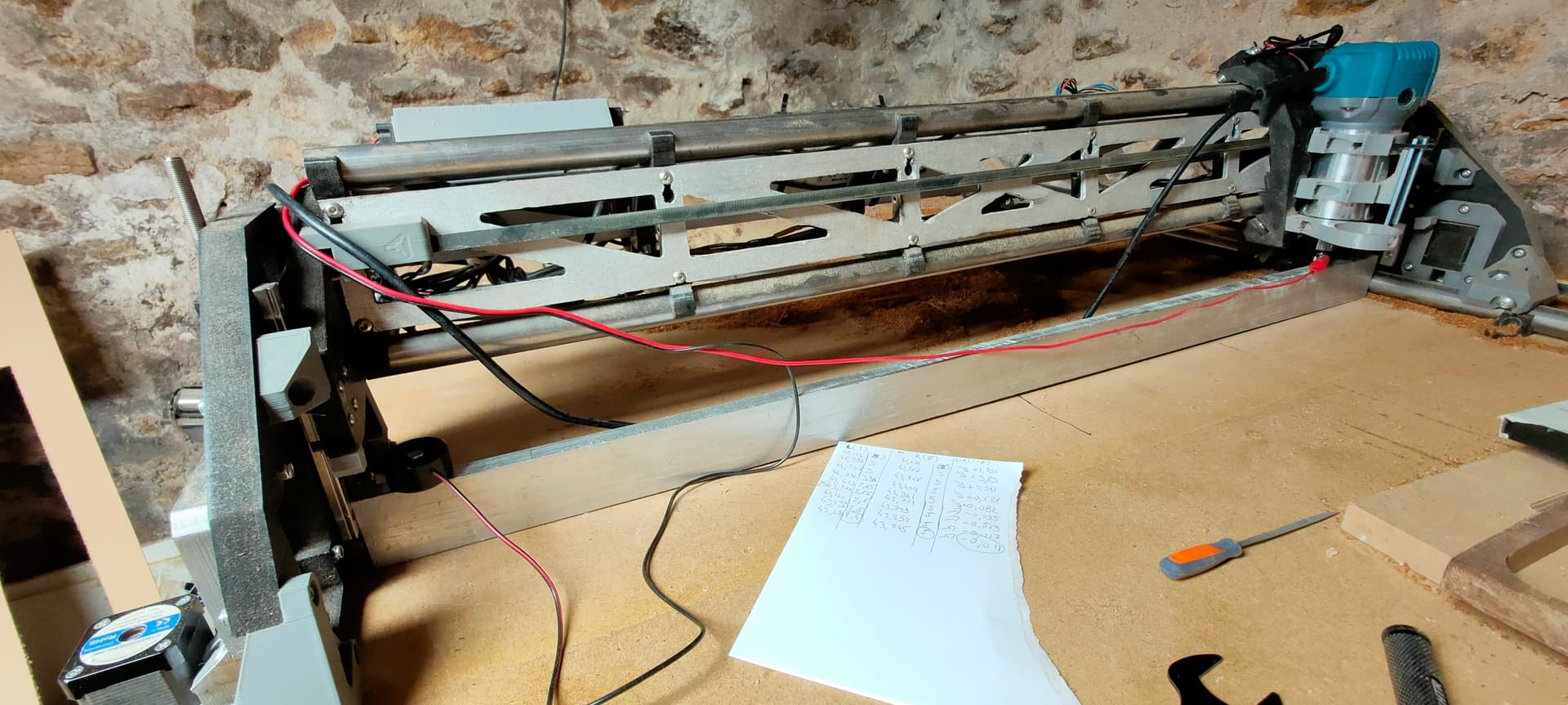
A large aluminium ruler used in masonry across the X axis
You can see the bow in the middle underneath it
I then put the probe negative on the ruler, and positive clamp on the bit
Then it was:
- X and Z homing
- Probe
- Move X → 820 (max)
- Probe
- Note the two values for Z from the probe result
- Adjust z motors
pulloff_mmparameter in fluidnc - Save, rince and repeat…
Once done, I trammed the router the best I could using small papier shims between the tool bracelets and the core, checking with the printed tool mentioned above
I still stand my point, wish there was an easier way to adjust the router position on the core on the LR3, this feels a bit finnicky right now, altough it can be done in the end…
Maybe two screws in the back of the core, in the middle of the brackets, to “push” the top or bottom of the router and thus tilt it forward/backward?
That would tacke care on the perpendicularity in the Y axis, but not for the X axis…
For this one, maybe have the brackets adjustable side to side? using an elongated hole?
Also wish we could automate the Z skew in FluidNC with two probes, one at each end of the X axis, and compensate for it in firmware
This could probably be done with a macro and program that does the routine described in this post and automates the procedure according to terminal output…
2 Likes
I’m new here and haven’t actually built mine yet…so bear with me…
Is getting the spindle perpendicular with the work surface what’s important first? Or is getting it perpendicular with the X gantry what matters?
With a 3D printer, I am usually trying to get my bed(work surface) parallel with my X because there is no re-surfacing, but my understanding is that the surfacing of the spoil board will take care of making the work surface parallel to the X/perpendicular to the spindle…
So prior to surfacing the spoil board, should the goal be to make the spindle perpendicular to the X plane of travel, which in turn should make the bottom surface of the tool parallel to the X?
Then re-surfacing the spoil board would then fix the work surface to be smooth with no lines, as well as parallel to X and perpendicular to the spindle as well?
I’m just trying to make sure I understand correctly so that when it comes time to do mine I will know why I’m doing what I’m doing.
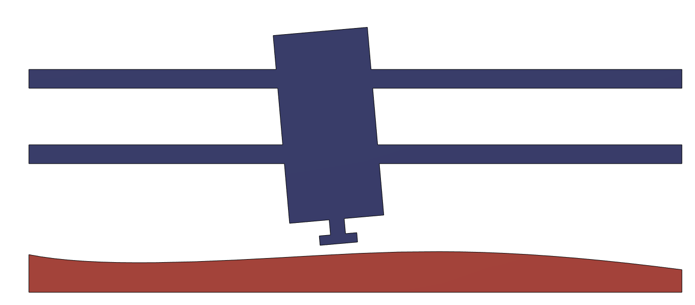
The thing is: if your gantry is not parrallel to the table (X axis), then the bit’s face won’t be parrallel to the surface too
Example with a table skewed in one direction and router skewed in the other
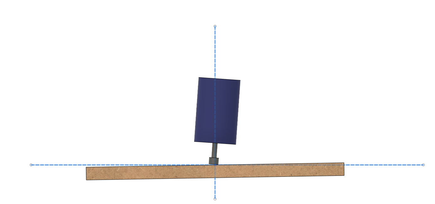
Surfacing with this setup, only the trailing edge of the bit would remove material, and lead to a poor finish
Also, if you machine both ways, this would become the leading edge in the other direction, and probably lead to some waves on the surface because it could bite more into the surface…
At least that’s how I see it…
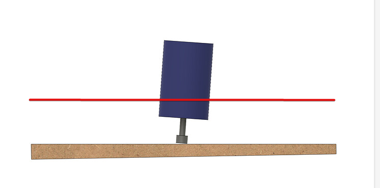
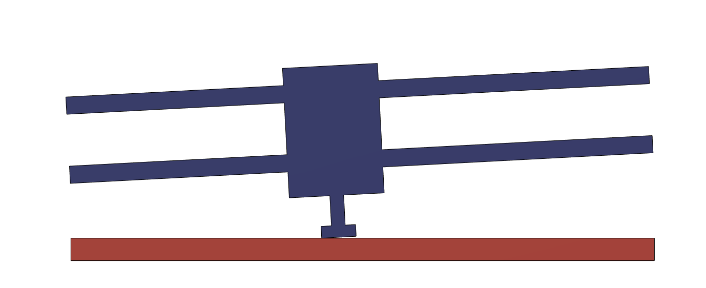
After Surfacing though, you’d get something like this

The leading/trailing edge of the bit would be parrallel to the table, but the bit’s face still wouldn’t be parrallel to the table
You could try to tram the router from there, but for the X axis, that would mainly be re-leveling the gantry parrallel to the table… which you could’ve done in the first place
I think getting the gantry roughly parrallel to the table is the first setup you’d need to do
1 Like
I’ll maybe need to think about it a bit more, but in your image, in order for that to happen, doesn’t the tool have to be “not perpendicular” to the X Motion?
Wouldn’t that red line have to be your X-Gantry parallel line in order to produce those results?
This right here is why the first thing I did after the crown was surface my table. I knew it wouldn’t be perfectly flat. But now it is flat to the LR and that’s what matters
1 Like
Makes sense…
But surfacing with an untramed router seems…Wrong?
You’d need to do two surfacing then? One first rough pass to get everything somewhat suare/parrallel to each other, then fine adjust the tramming, and re-surface?
I do agree that “spoil board roughly parallel to X gantry” should be done first, but it seems tool perpendicular to LowRider X plane should be more important than perpendicular to the table, as the surfacing would correct minor differences
If you’re roughly perpendicular to the table in the first place (that is , gantry roughly parrallel to the table), the tool’s tilt in the mount should be neglegtable after surfacing, but still present
For small bits that’s not a big deal, but as soon as you try surfacing with wider bits it quickly gets quite noticeable
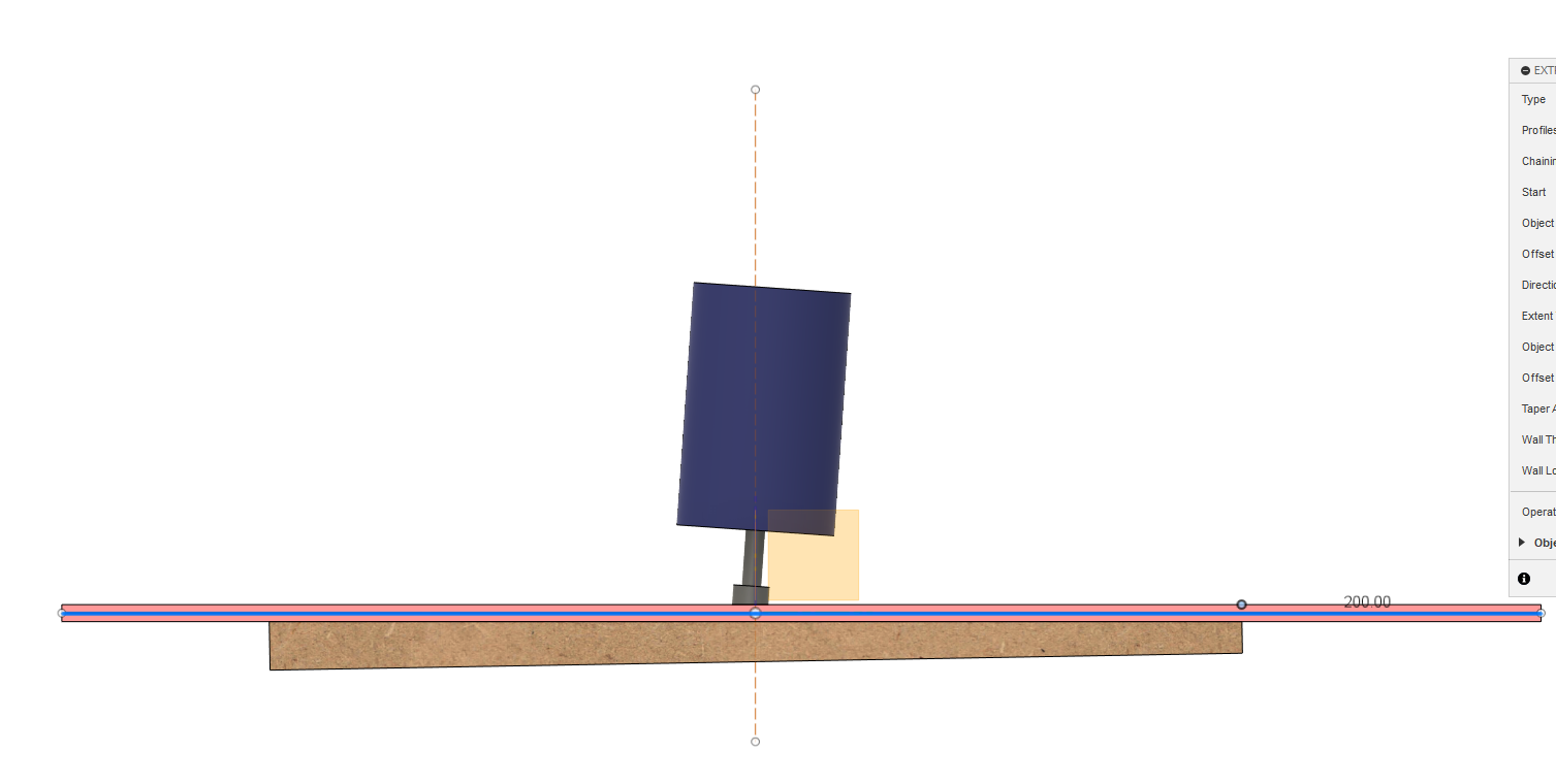
Say you start with a “slightly” crooked gantry ![]()

Now we’re surfacing “as is”
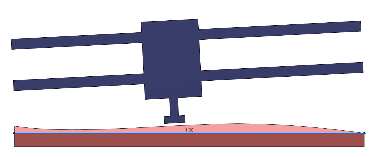
After this, you get:
Note: This is broadly exagerated but I’m trying to visualize clearly what’s happening
So , all in all, you’d still need to make the bit perpendicular to the work surface to avoid waves when surfacing, and on the LR3, this can only be done by adjusting the gantry anyway (the tool is fixed in it’s mount and in the core)
Maybe then it’s just simpler to adjust the gantry in the first place before surfacing
For the sake of it, same exercise with a gantry roughly parrallel to the table, and a tool tilted in the mount


You’d need to “counter-tilt” by making the gantry un-parrallel to the surfaced table after the fact to compensate for the tilt