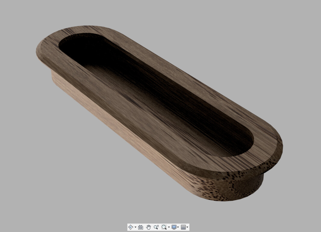
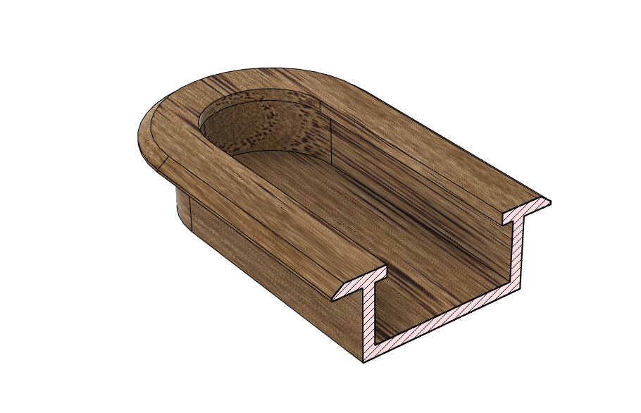
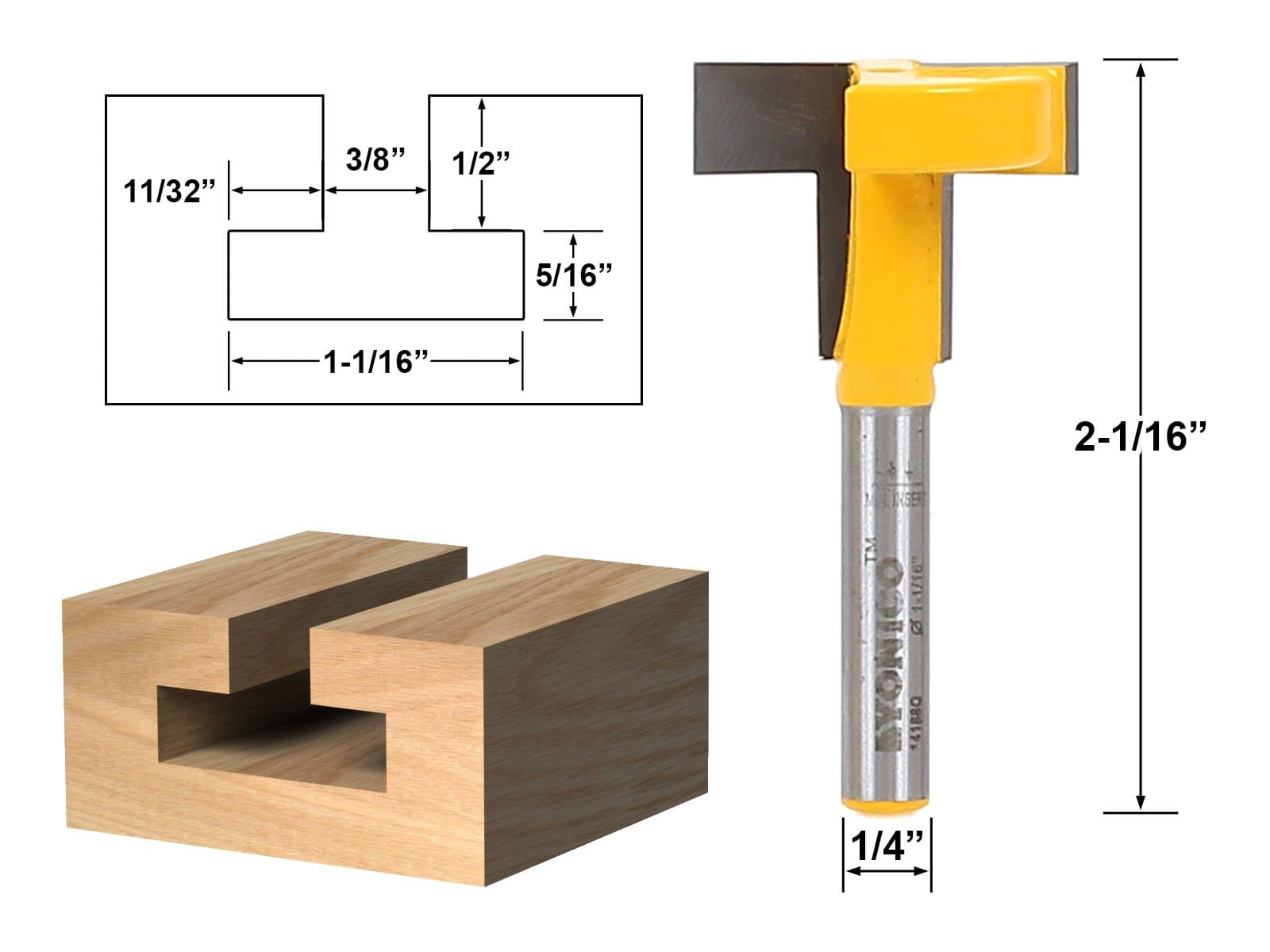
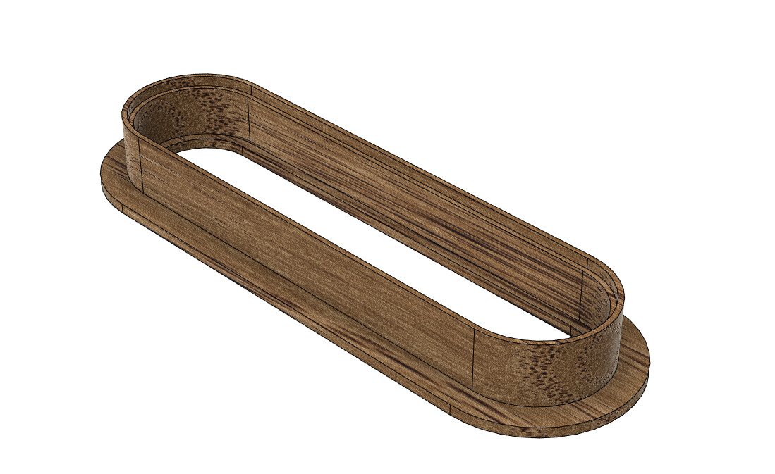
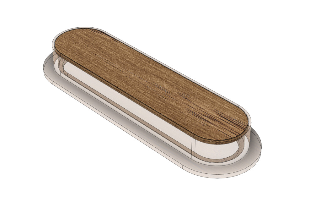
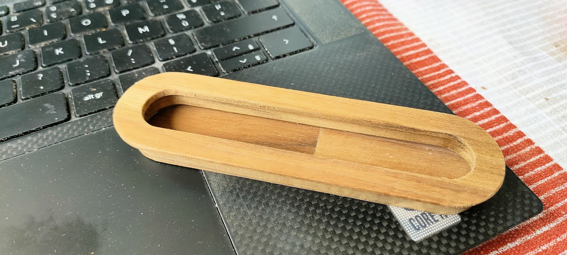
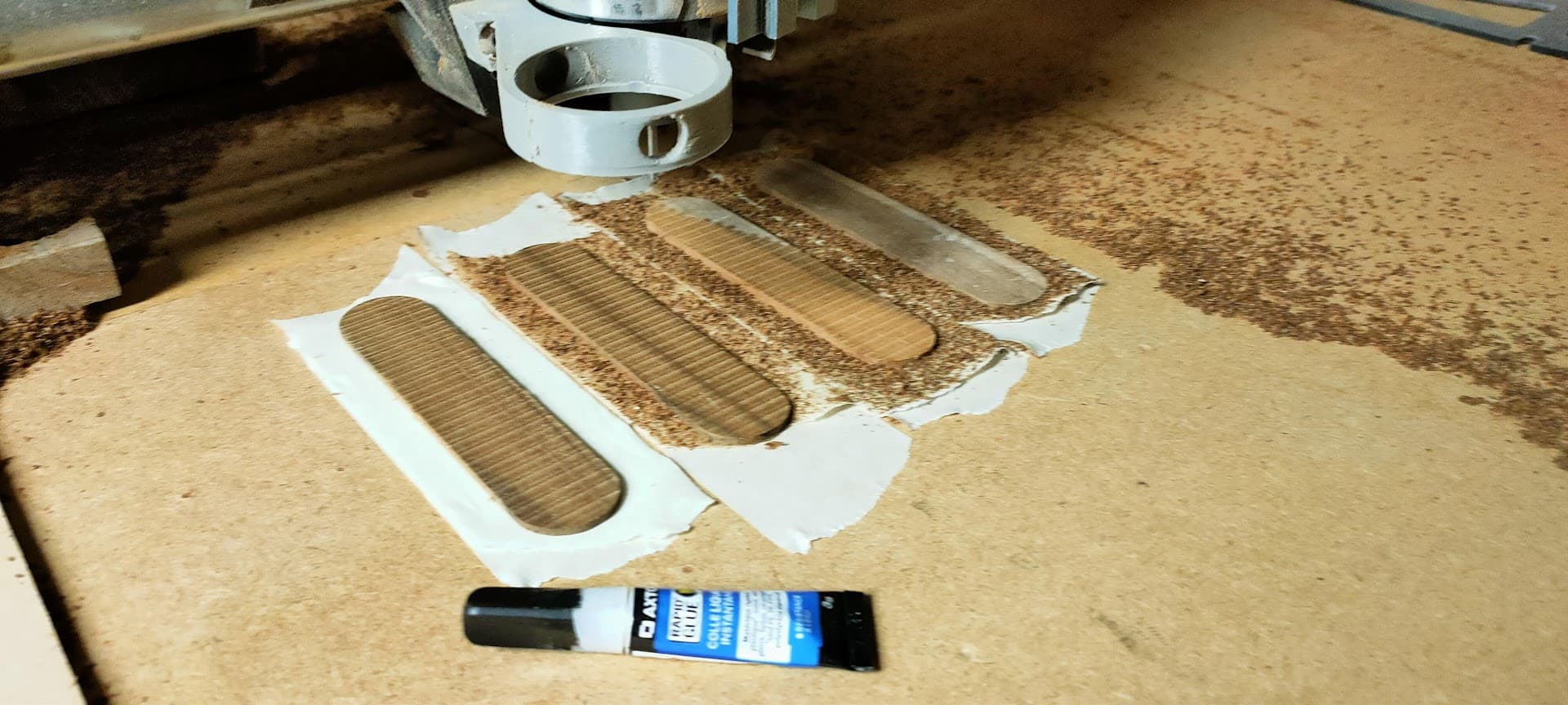
Making a straight pocket in the middle is quite straightforward, but how would you mill this small lip?
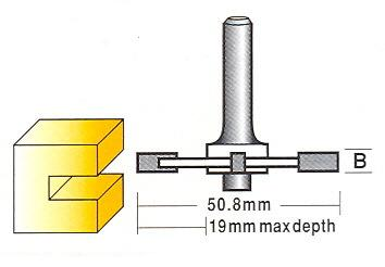
I thought about first clearing the inside of the pocket with a straight bit, and then hav a second toolpath that cleans the inner recess using a T shaped or a slot bit like those ones:
That’s very interesting. I’m not sure what you could do. I agree with clearing the inner pocket first. But i have no idea what you would use for the lip. If you try to pocket that but start lower its still going to start from the edge and run right though the lip in one spot. I’m curious to see what others say about this!
In Estlcam, whst I might do (assuming the second bit)
Define the bit by it’s outside diameter (1 1/16" = 26.988mm) and use the CAD drawing of the larger portion of the hole. Assume that the opening in the center will be larger than 26.988mm.
Cut the hole a little deeper than the shoulder of the bit using a tiny step-down, that’s 5/16" (7.94mm) so say cut it 10mm deep, that leaves about 2mm.
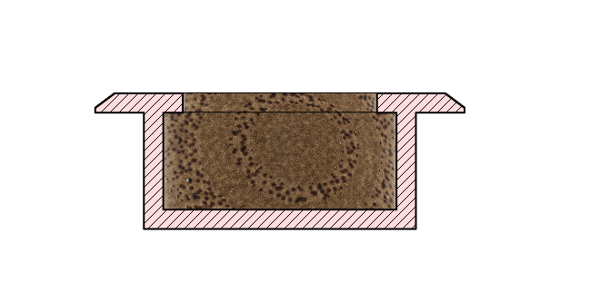
The trick would be to do a full depth finishing pass. Make it say 2mm allowance for the finishing pass, which will leave a lip 2mm deep and 2mm high.
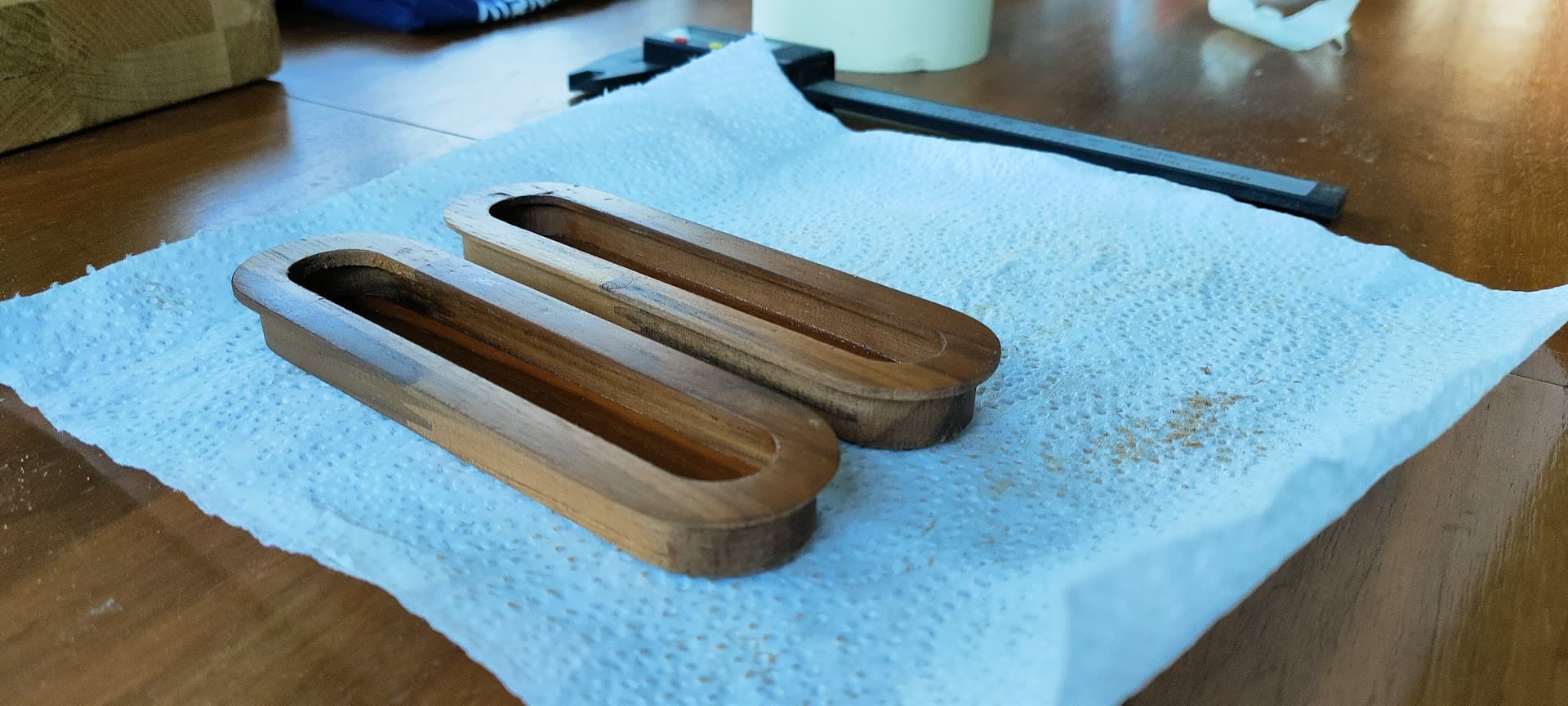
Personally, I’d divide the job into two pieces (the well and the flange), mill them separately as one-sided jobs, and glue them together. I’d also speed things up by surfacing/planing the stock to near or at the finished thickness for each piece.
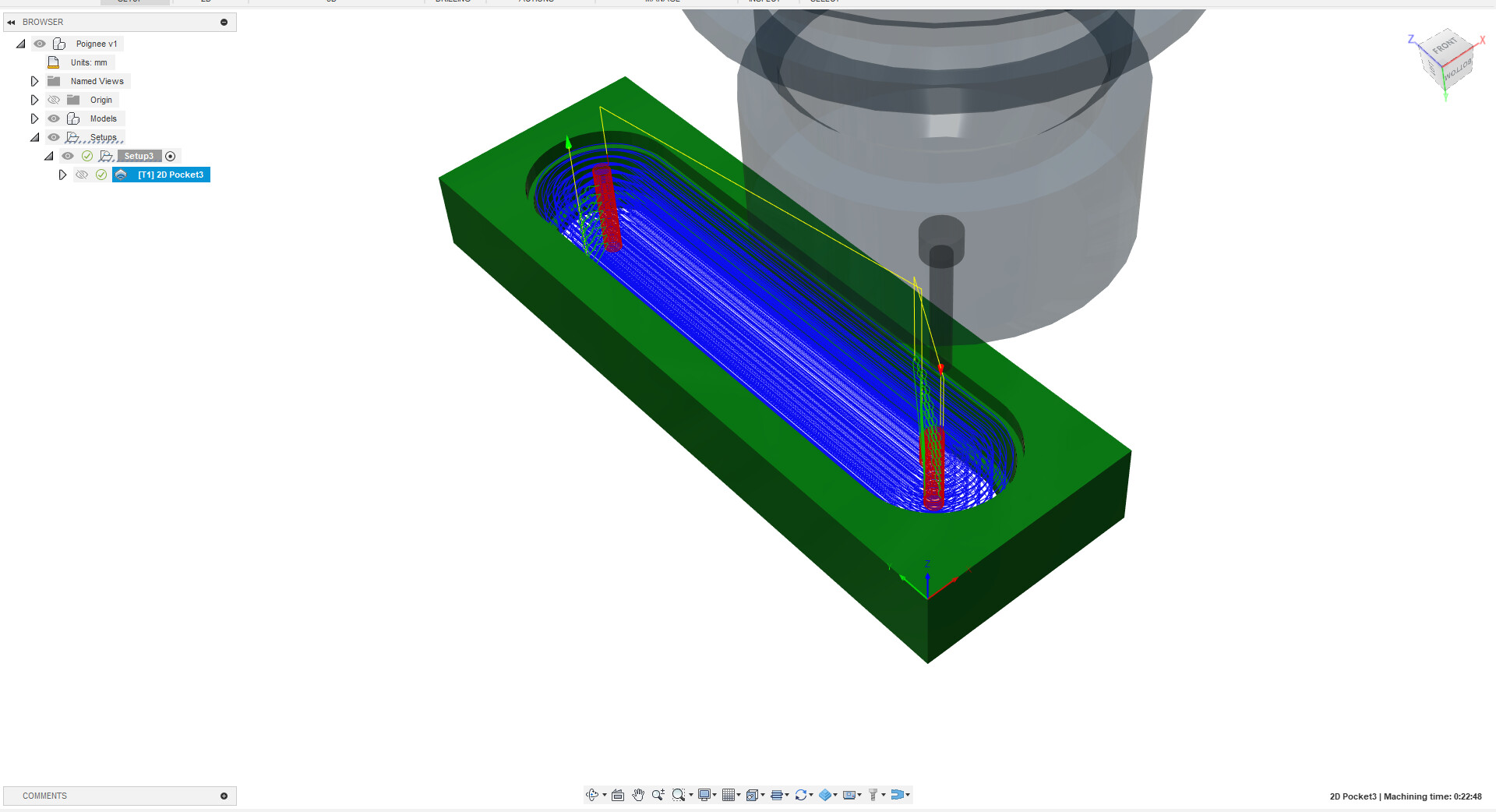
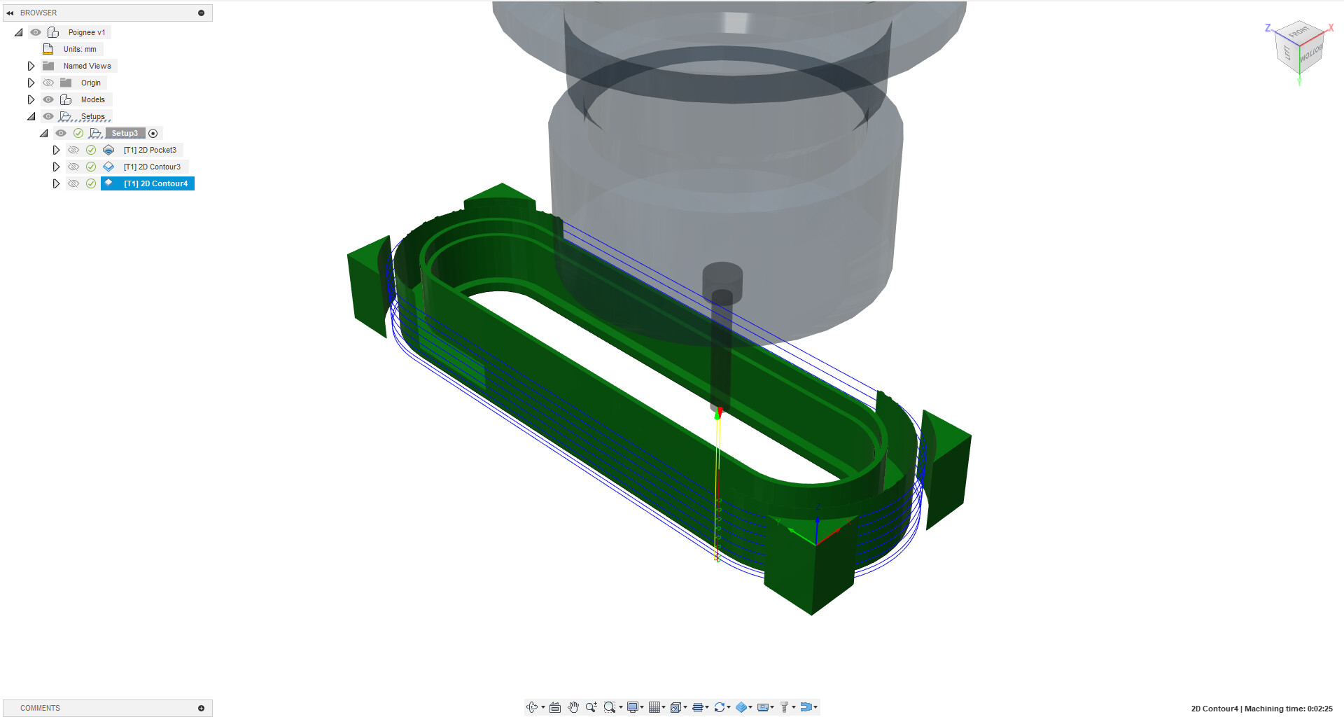
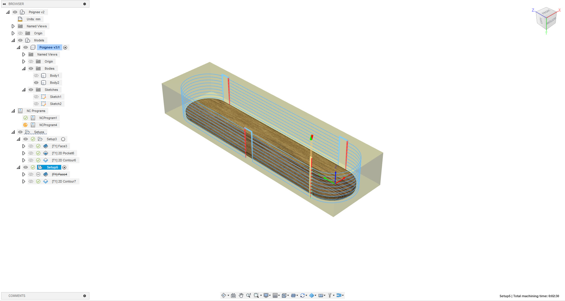
In Fusion 360, I’m sure there is probably a right way to do this task, but the only thing that comes to mind is to give up on all the calculations that Fusion 360 does for you and define your own paths for the bit. Then you can use the 2D Trace toolpath to make the cuts. You would need to do all the calculations yourself including depth of cut, and offset for the diameter of the bit. Also, you would want to pocket the inner diameter first before using the slot cutter.
Note: I still have a small problem on this operation, if I’m making a 2D pocket, the CAM will also clear the inside Selecting the two sketch profiles seems to do the trick, but I’m not 100% sure…
Not hard, but that would waste a lot of stock as I’d need to surface out 18mm off the top to make a 2mm thick cover… time and effort consuming…
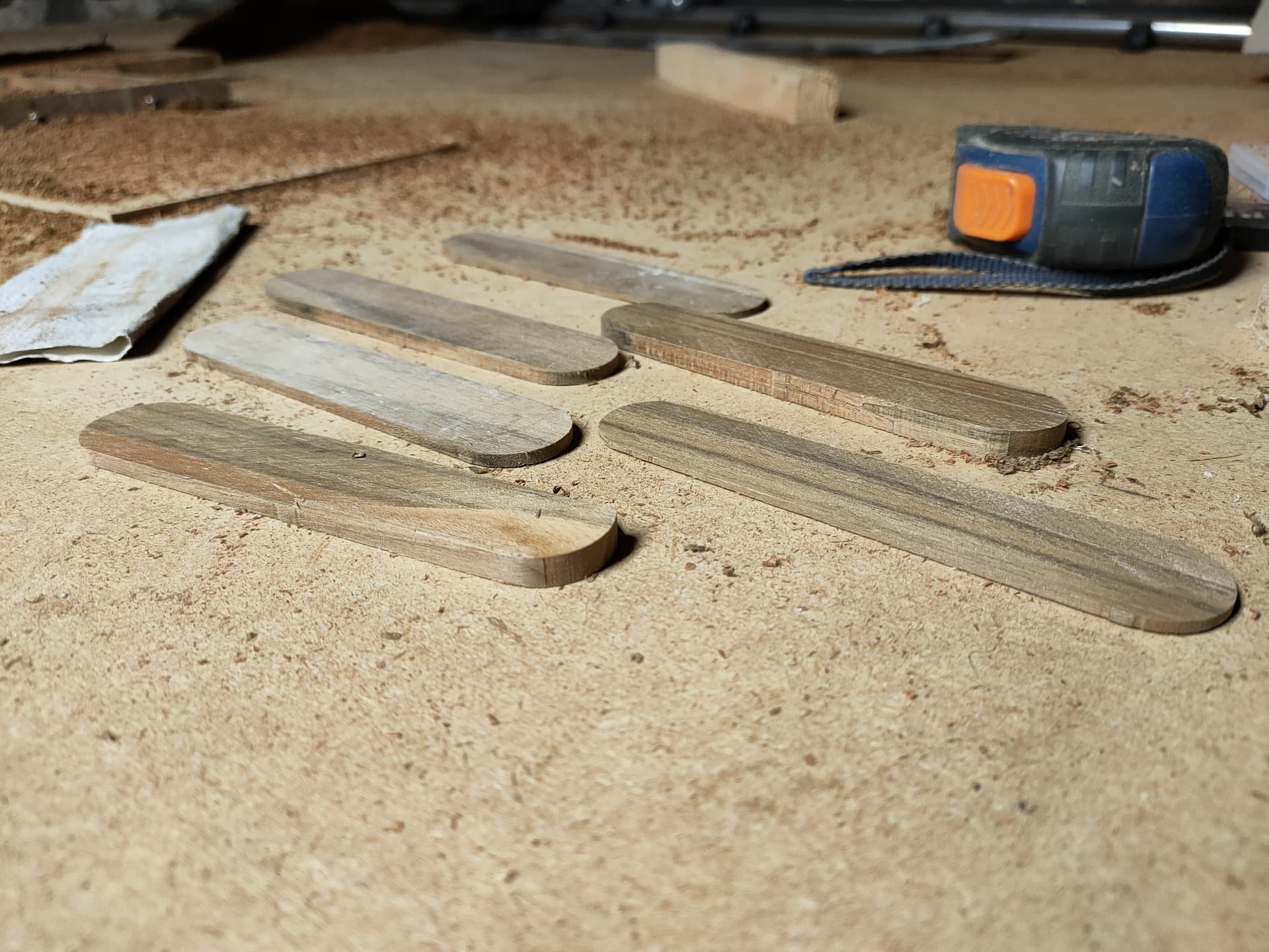
You would cut the piece slightly bigger than your cover or face, then resaw the wood. You can get at least 2 and perhaps as many as 4 pieces of stock out of one 18mm thick piece of wood. For this small a piece, even a handsaw would do the job, though a table saw or a bandsaw would be easier.
Except I would mill everything from the black and glue the cover on the black
I suggested doing the face separately because of the chamfer on the front side of the face plate. Plus, it hides the glue joint a bit better.
I’d be interested to see if/how you can do it as described though
I spent a bit more time on the problem. Fusion 360 does allow you define slot mills, so defining the bit is not a problem. Searching on YouTube returned a few hits using slot mills. They were doing the simpler task of cutting a keyhole for hanging a sign, and, for the couple of videos I skimmed, they used the Trace toolpath as I suggested. You would need to create a sketch at the right height (offset plane) for the tip (bottom center) of the slot mill to follow. The tricky part will be getting the slot mill to enter inside the opening.
I accomplished exactly this trick when I needed some keyholes to be CNC cut using a T-slot bit. I did it by manually drawing the cut line with its beginning at the place where I needed it to drop the bit into the material, then having another point on the line, at the extent of where I needed it to carry the T-slot bit, and then I made a very very tiny U-turn, and brought the line back, in a parallel way, to right beside where it came in at. This controlled the starting point and ending point, and allowed me to carry the bit around while making sure that I entered and left at practically the same spot.
I think that’s the right way to do it indeed…
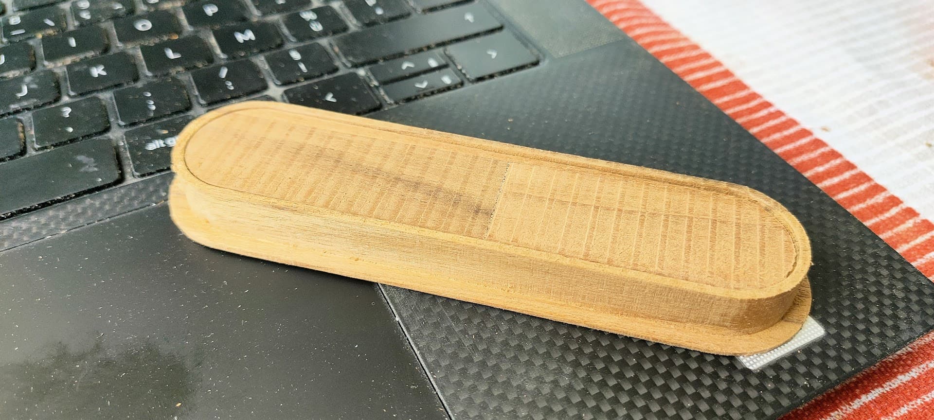
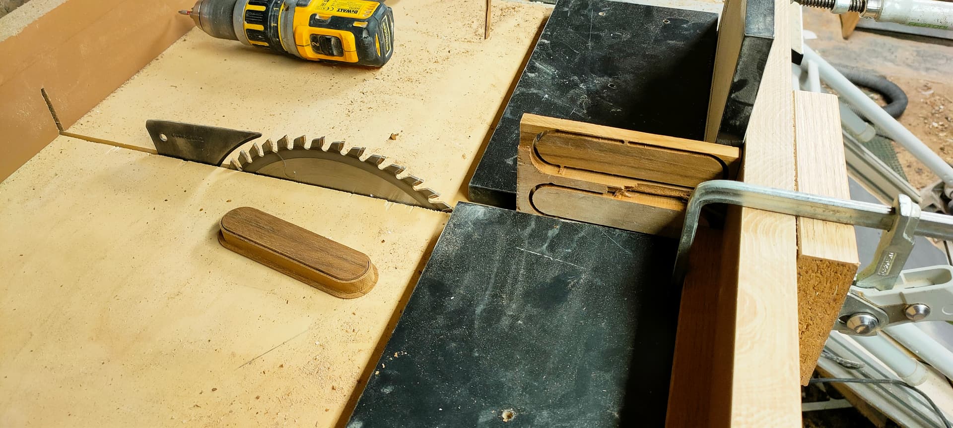
Cut the contour of the piece through the whole stock, leaving a tab on either side , and then re-split it using a bandsaw or table saw
But I’m lazy and if I can do everything on the LR3, I definitely will
Yep, makes sense
Although, because I’d need to change to a ball endmill for this feature anyway, I’d still cut everything from the back and then flip it and add the finishing features
But I gave up on the little chamfer anyway, on a 2mm thick piece it’s not that visible, and could be added with a small planer or light sanding
I will definitely look into that! Thanks for the pointer to the right operation and methodology
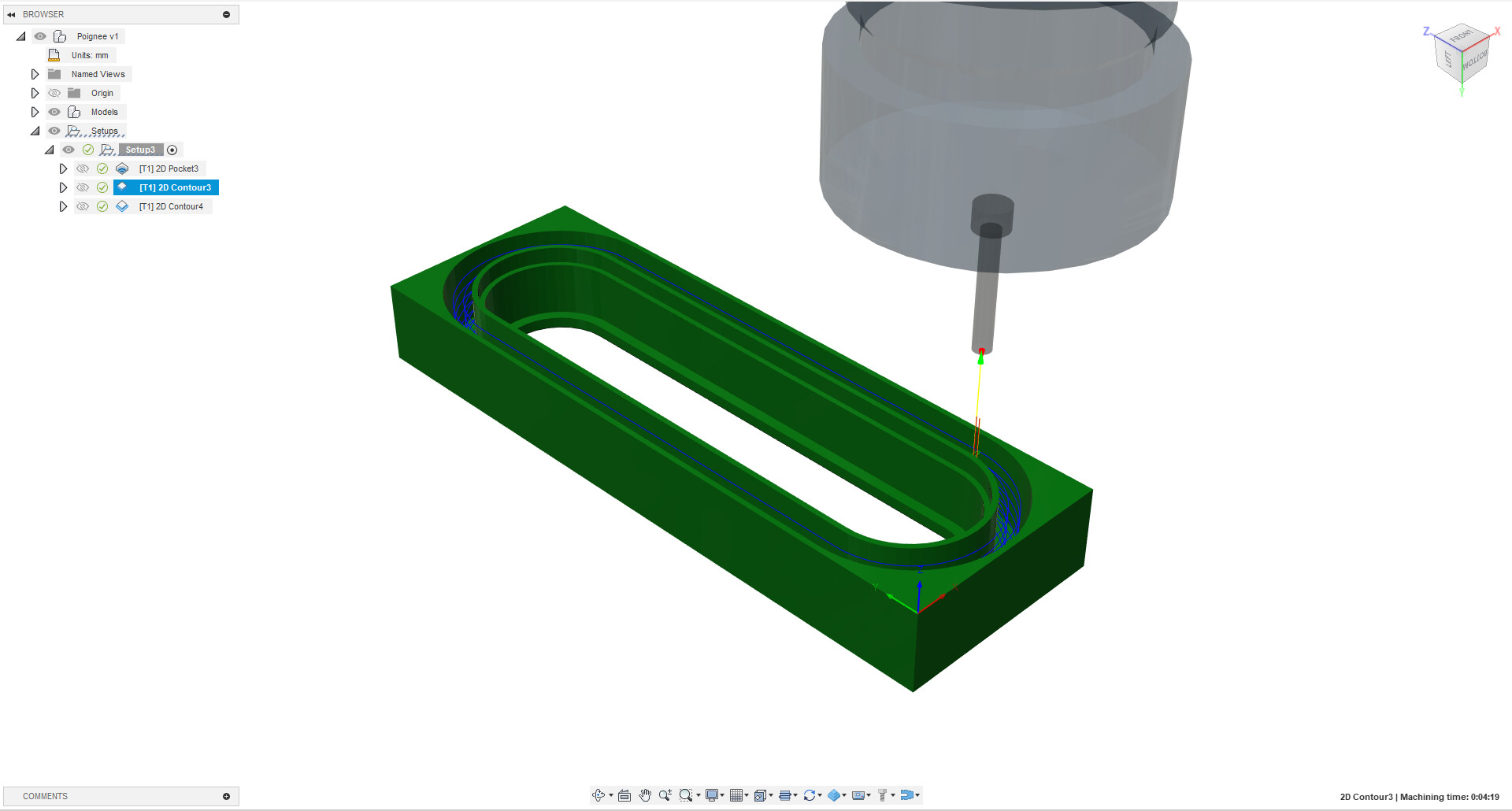
I just ran a quick test, and, with a slot mill defined, you can use a Contour toolpath, and fusion handles the offset for you…none of the calculations you would need to do to use a Trace toolpath. You would need to create multiple toolpaths for different depths. This can be handled in the Heights tab.
If you were going to make 50 of them, and you wanted to skip the glue, you would at least need another tool to rough out the middle. Then make sure the lead in plunges in the middle and only cuts at one depth (or only cuts deeper than the flange, at least. Even with the right CAM, it seems like a difficult cut to succeed.
There are so e examples for keyholes using a keyhole bit. This would be similar but different.
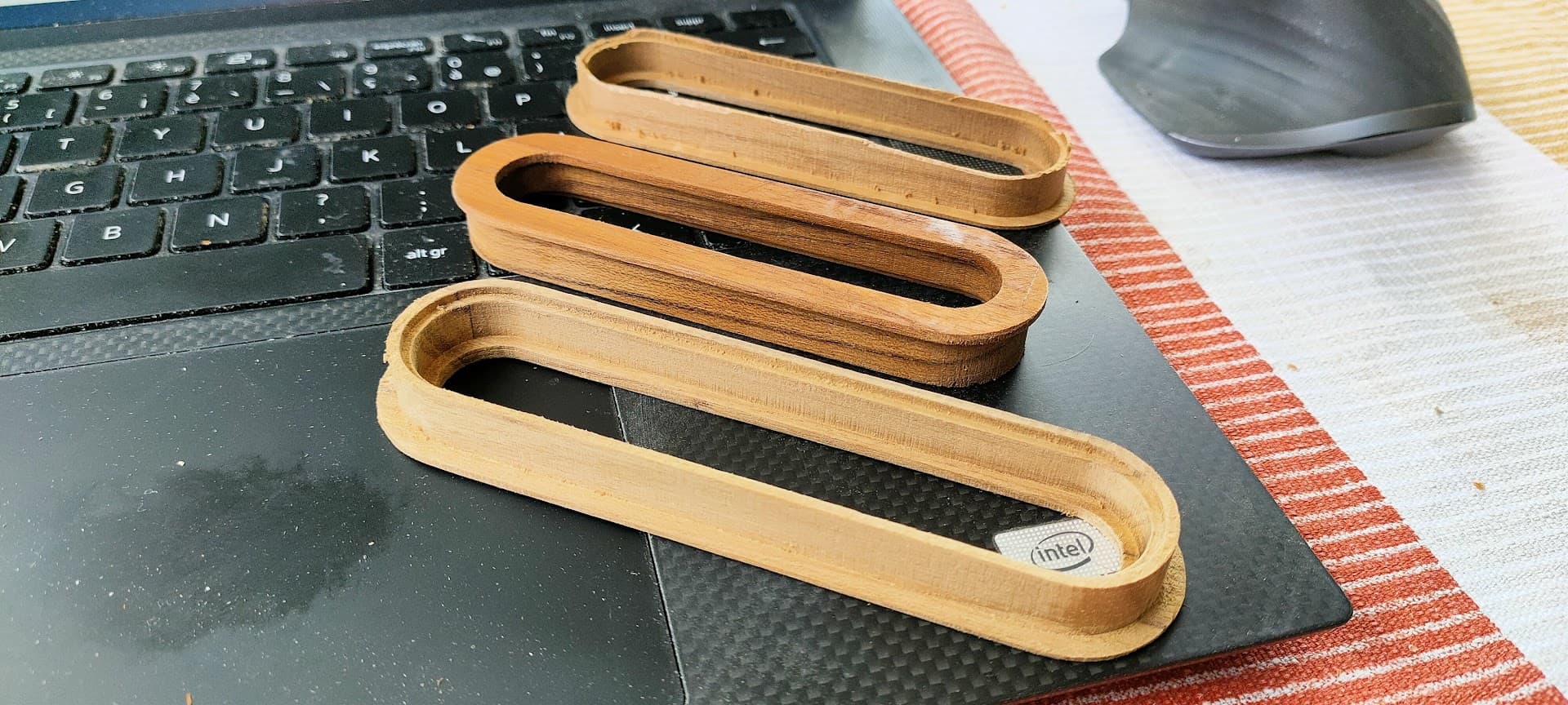
Yes I think that was the simplest approach, no tool change, no fixture, the only difficulty is to cut the thin back plates on the table saw, but if I were to make large numbers of this, I’d devise a jig to cut them (like a thin rip jig)