Right, I don’t have an easy way to make a drawing right now, but I guess that was what I was getting at.
In my mind, the only way I can see to guarantee no lines, is to make sure that the bit is perpendicular to the plane that the X motion of the LowRider creates. So, I guess that was where my question was rooted.
I don’t know how much play or adjustment there is for it, since I haven’t started mine yet, but just was wondering if it made more sense to verify that the tool was perpendicular to the machine first when trying to get a smooth, trammed surface.
So in the end, with your digital level, you’d want to see 90° from the X rail to the bit first, get the surface as close to 90° to the bit as possible, then the surfacing would guarantee a smooth 90° from the bit to the spoil board.
Because the rails are supported by the sides that run on a fixed surface (you can’t surface under the wheels or under the Y rail)
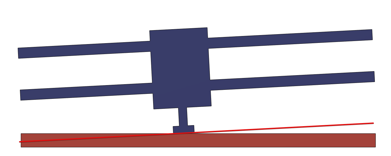
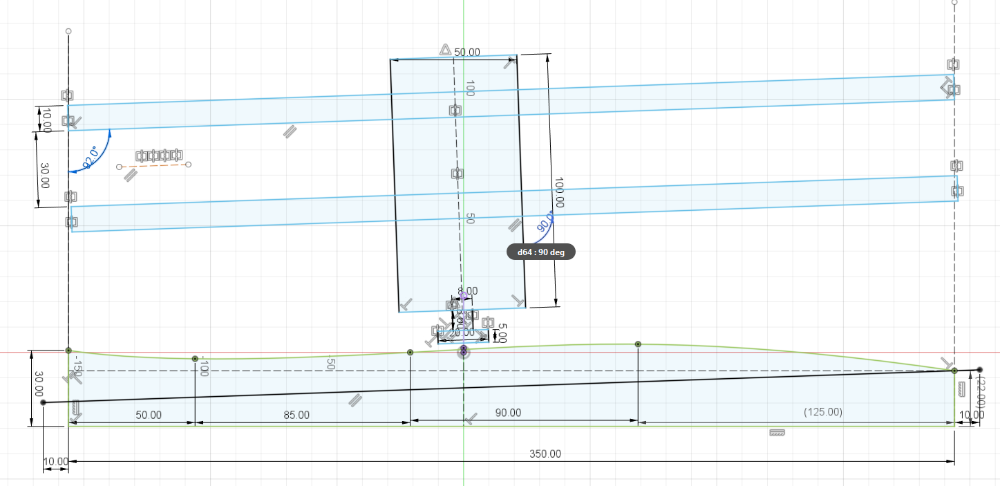
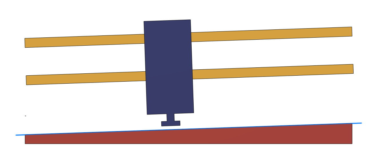
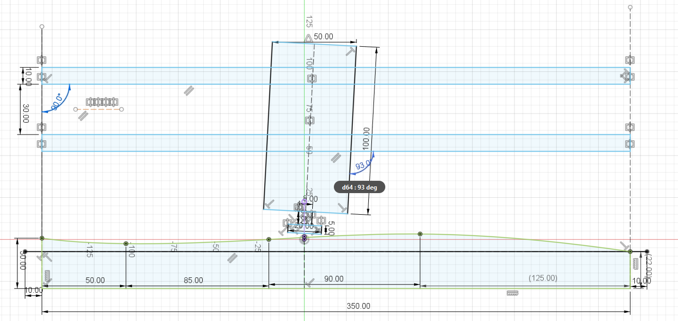
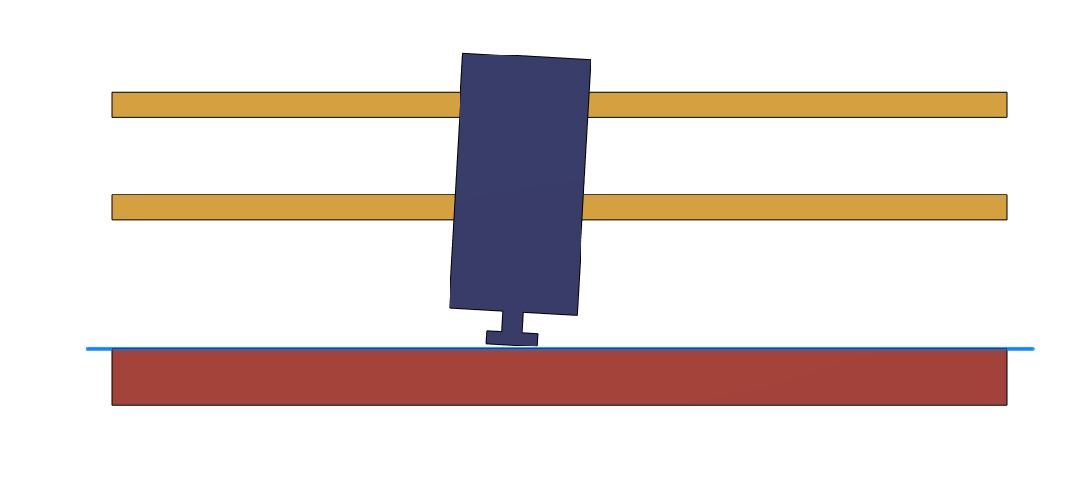
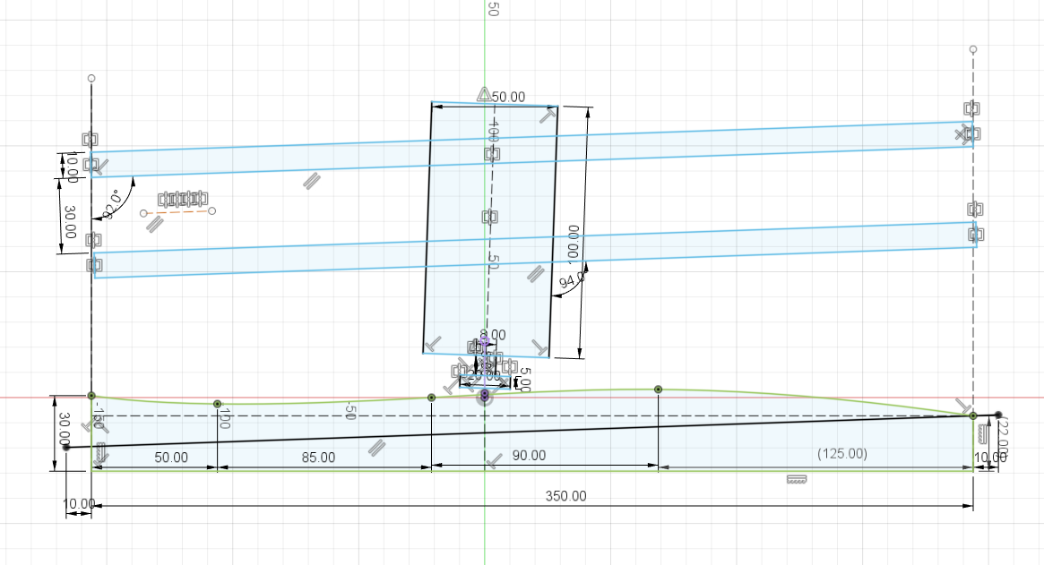
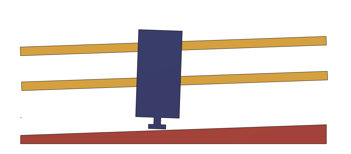
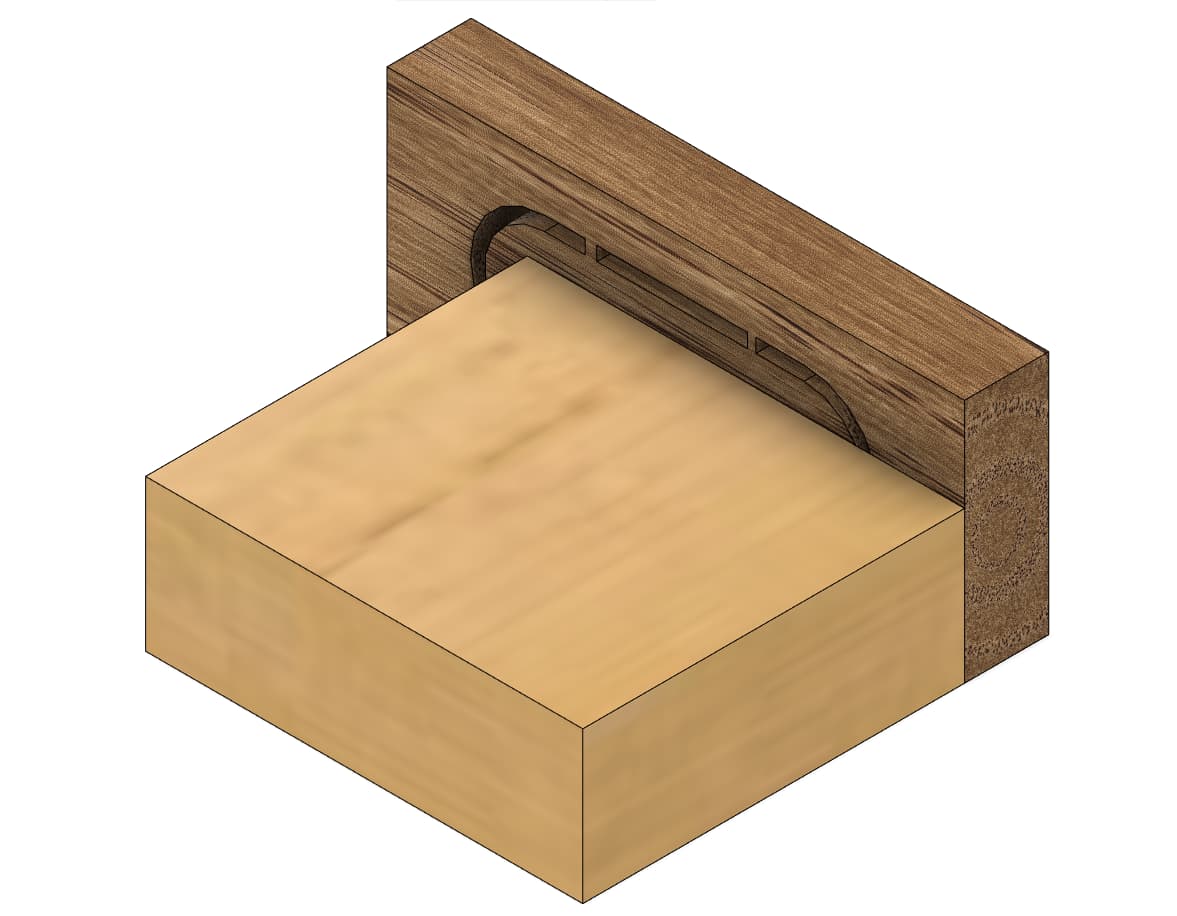
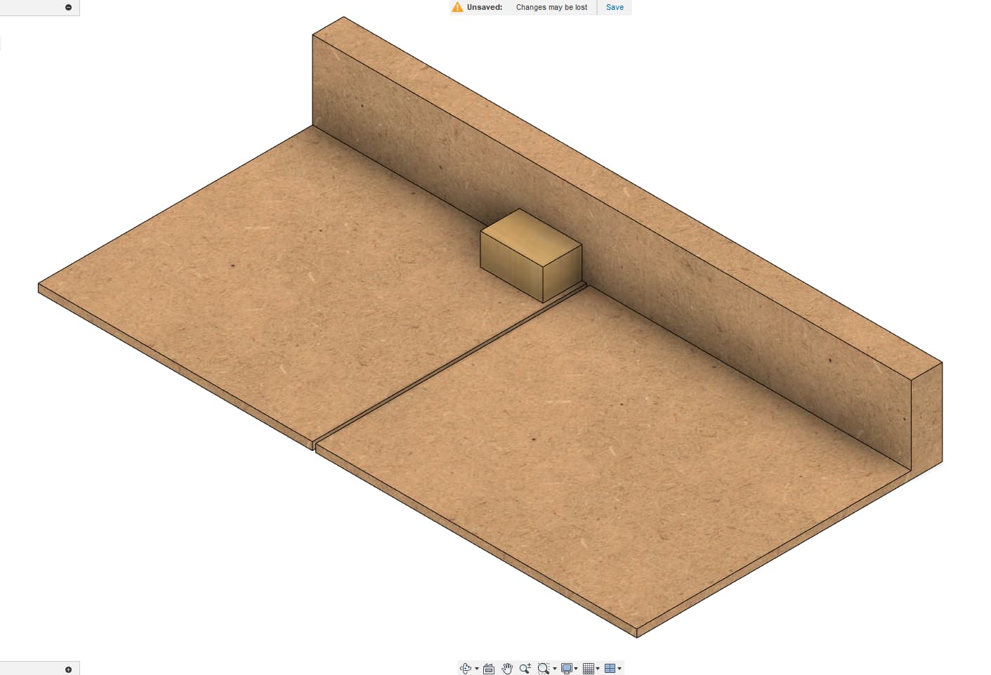
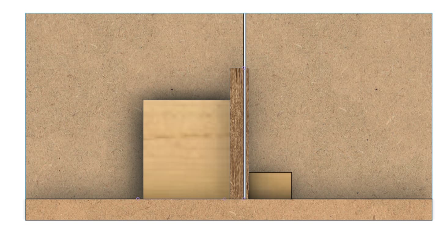
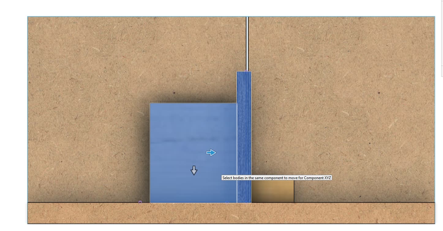
Note: I added a few drawing with the gantry roughly parrallel to the table and the tool slightly tilted in the mount somehow…
You’d end up making the gantry un-parrallel to the table to compensate for it…
The reality is probably a little bit more complicated anyway, because it’s probably a mix of both of these (gantry not perfectly parrall to the table, and router not perfectly perpendicular to the gantry)
EDIT: I see my first drawing is wrong, I’ll try to redo this…
That is what I would expect too, since the tool moves along the rails, the bed will be parallel to the rails in the X dimension. If you get your Z endstops wrong, this is what would happen.
If you tram the machine to that, it will be OK, since the tool will still be perpendicular to the motion axis. Correcting the Z endstops will fix it, though if gou surface the bed that way, it’ll be weird.
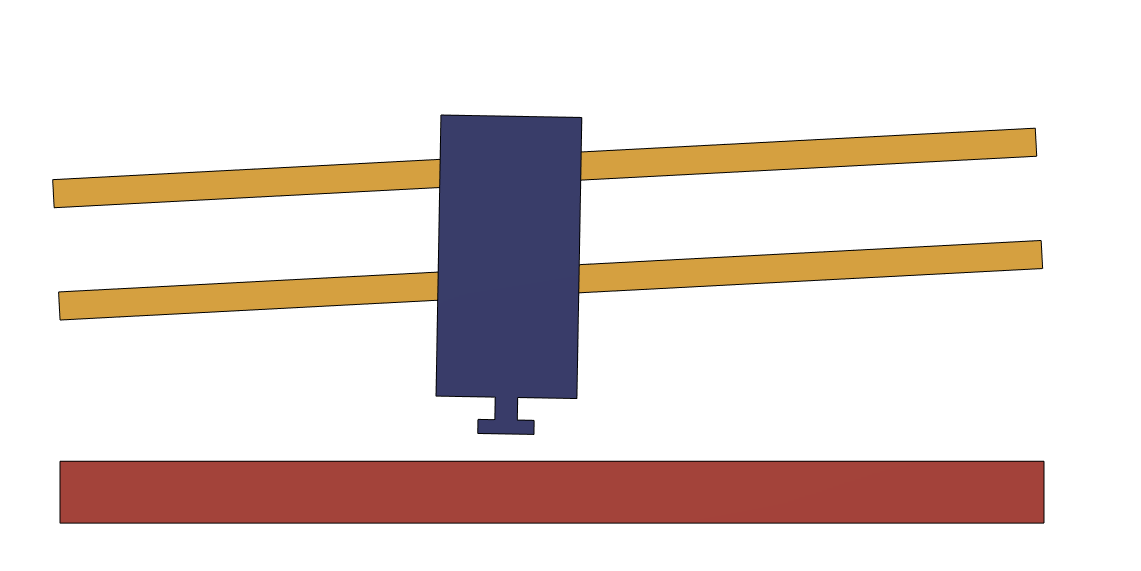
Having the gantry parrallel to the table in the first place does not affect the end result, but allows you to remove less material
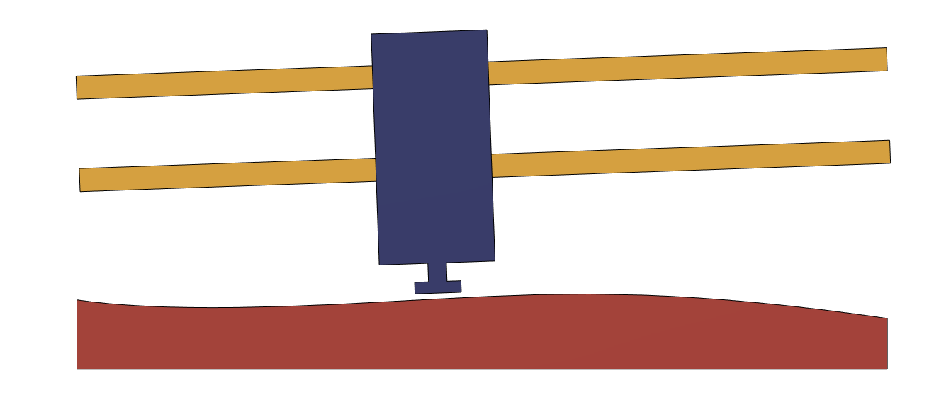
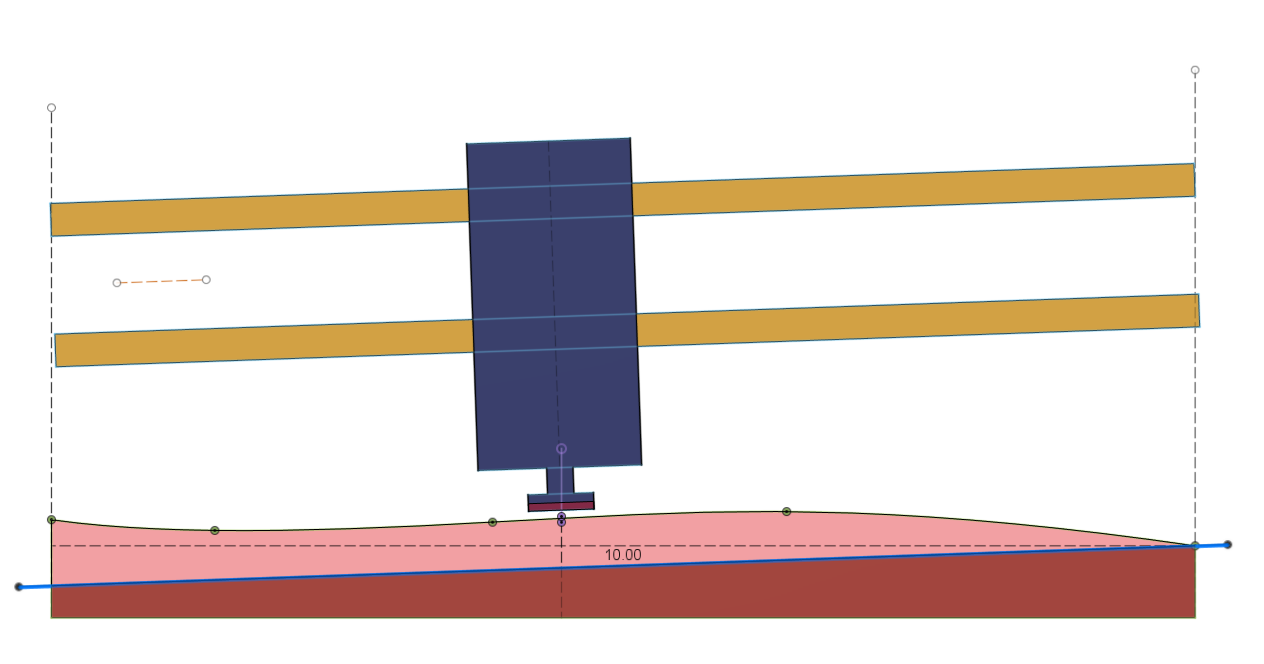
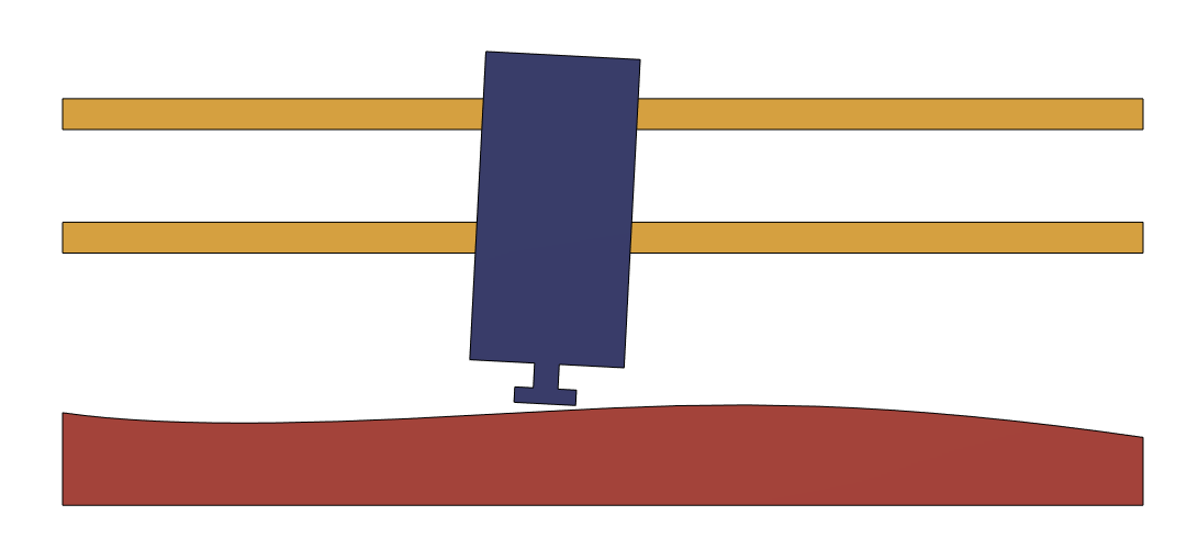
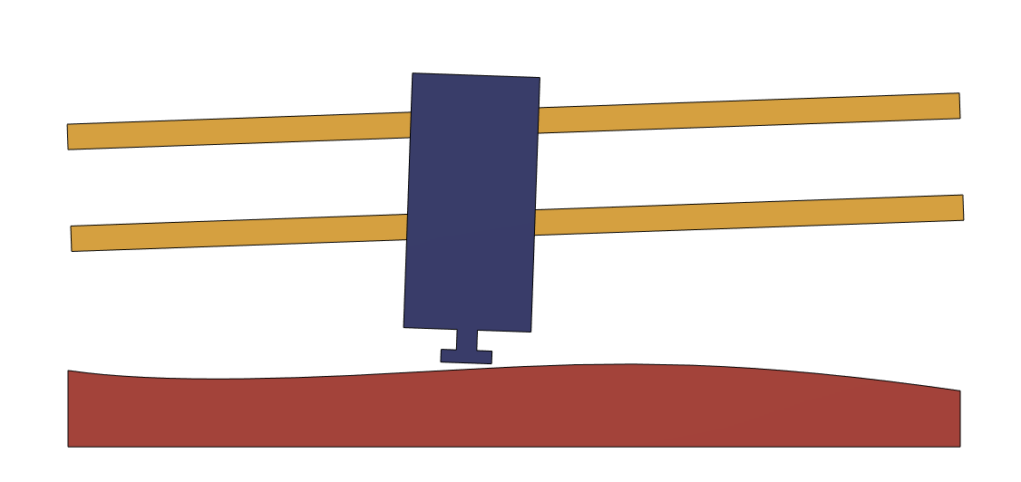
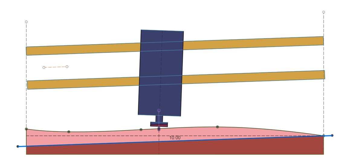
After surfacing, the gantry is parrallel to the work surface, but the tool is not necessarly perpendicular to the work surface
Only the leading/trailing edge of the bit (depending on the way the tool is tilted) will follow parrallel to the surface, I don’t know if you would get significant marring from the difference of eight between the edges?
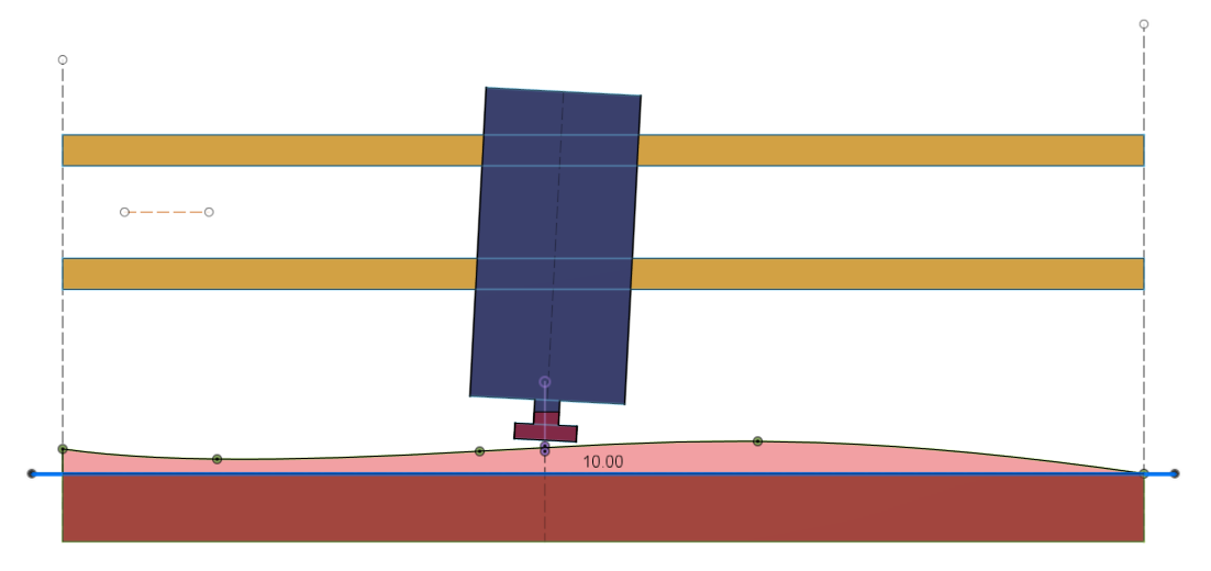
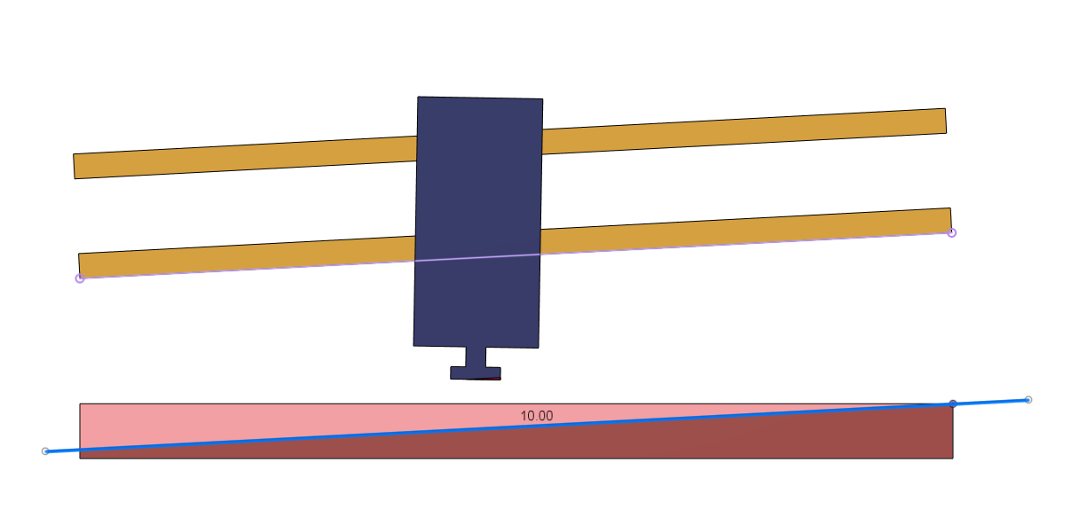
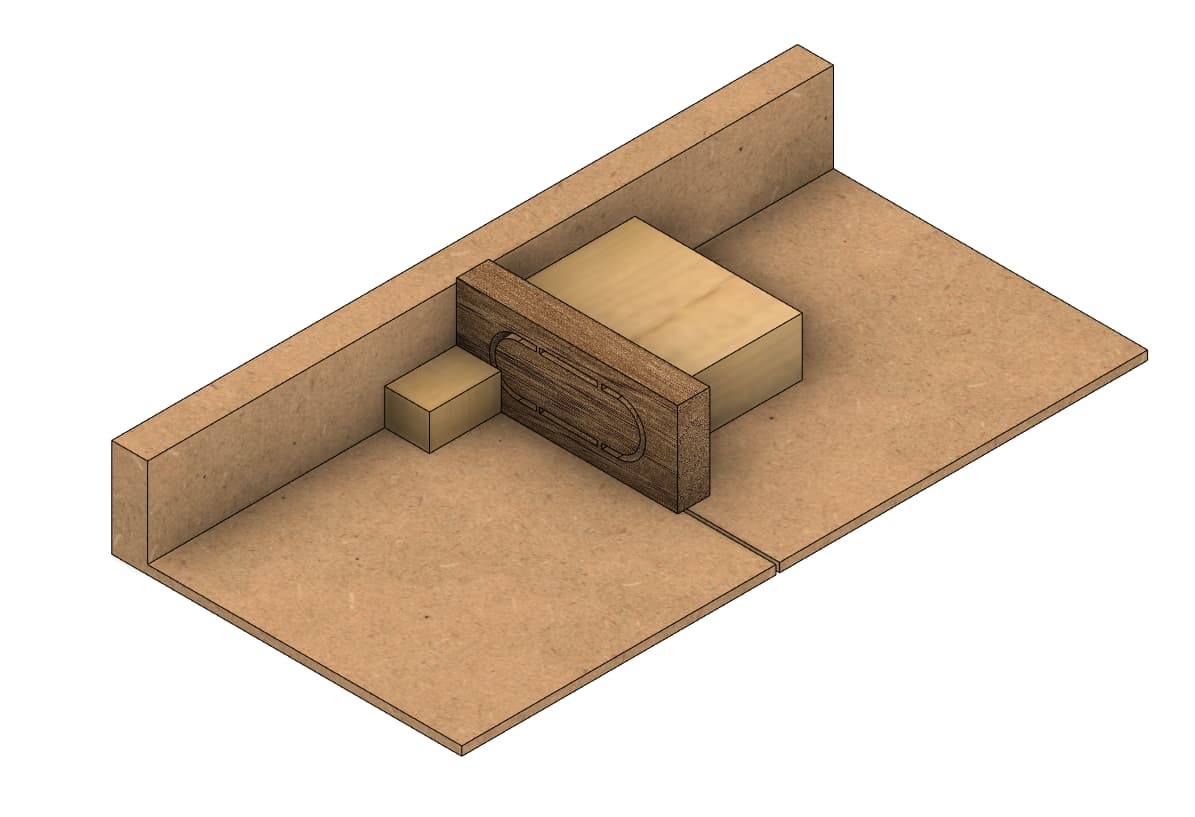
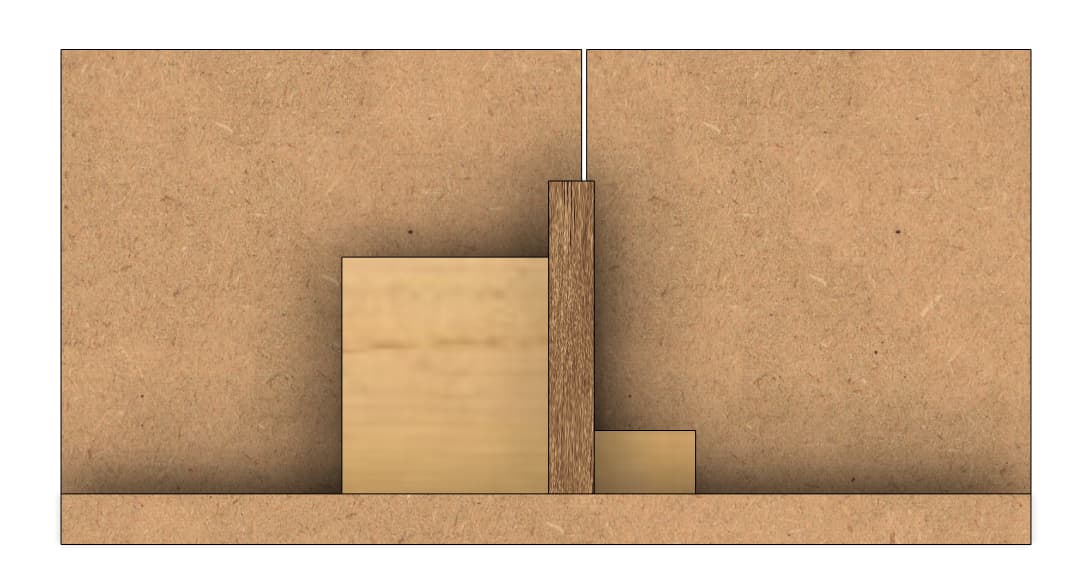
Following this, you’d need to adjust the gantry after the surfacing to make the tool perpendicular to the surface, and then re-surface the work area…
This is the only one that leaves the surface of the bit parallel with the table, which is why I was saying I thought tool/bit perpendicular to the gantry was most important.
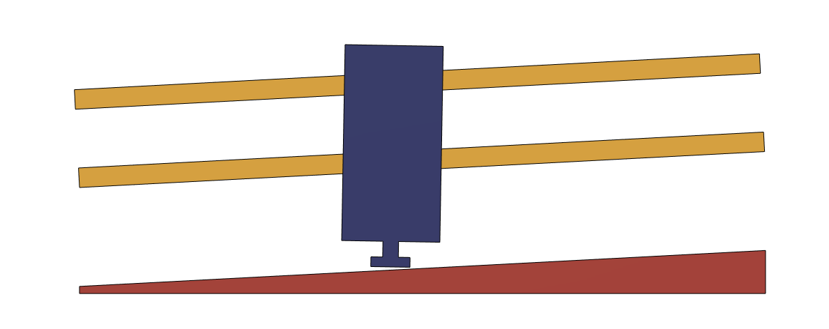
Starting “roughly parallel gantry to spoil board” means less material removal, but the tool will correct minor inconsistencies after surfacing, so it feels like tool being perpendicular would help work things out easier.
I’m really not sure what kind of adjustments there are for making the tool perpendicular, but I guess I just assumed there were some.
Thanks for all the effort in the images. It confirms what I was thinking.
If after surfacing the tool is not perpendicular to the surface, adjusting the gantry and re-surfacing would put you right back where you started with the tool not perpendicular to the surface again, right?
That’s the point… there’s none
Not that I know of anyway…
You can shim the back of the mount to adjust for tilt in the Y direction, but for X, the only way I see is to adjust the gantry…
The skew should be pretty small in this axis though, the core is pretty rigid and not that wide…
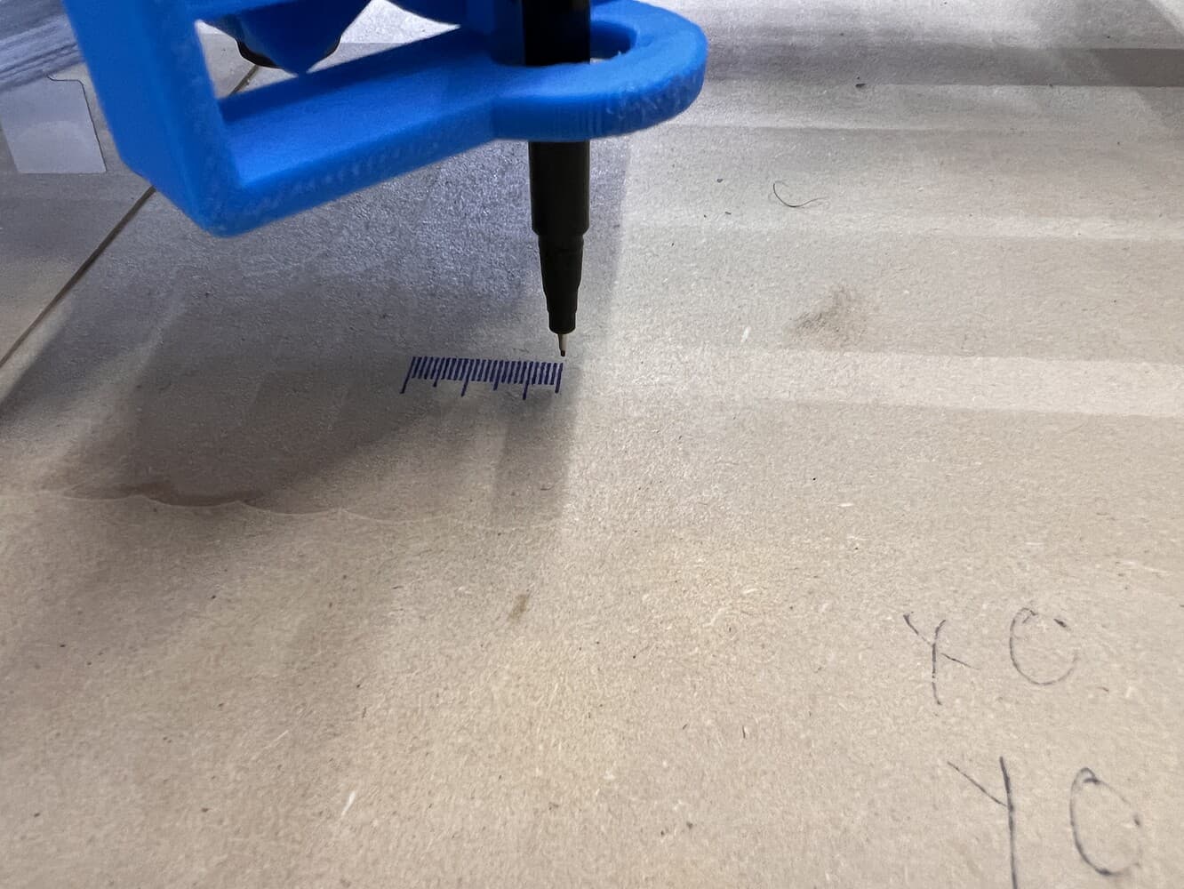
Still, I see my tool is not perpendicular to the table in the X axis, and I cannot determine if it’s from a tilted gantry, tilted table or tilted tool…
Seeing a little bit clearer now (thanks to your reflections and drawings I did), I’ll try a few more checks tomorrow and see what’s going on…
I’d like to try and minimize the amount of surfacing I have to do if possible…
We just chewed up more material, and the tool is still not perpendicular to the work surface
Or am I getting something wrong again? (3.am here :p)
Not surfacing (skipping the last step) would keep the bit perpendicular to the surface, but the move wouldn’t be parrallel to the surface… unless you compensate for it in firmware, which is… not advised in cnc applications
That would signify: if your tool is tilted (not perpendicular to the gantry in the X axis), you’re left on your own… no way to adjust
I don’t really think we should see such drastic tilt on this axis because of how rigid the core is…
I really need to check on mine, but I think it’s a combination of other factors that make it seem non-perpendicular to the table
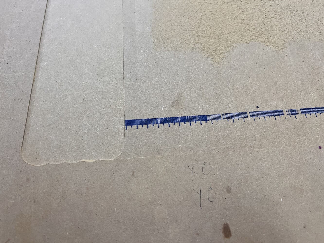
After running the second surface you can see it was much more flat. Now I have no idea on all your models where my table and router stand. But it looks good from standing at the end of it and I haven’t had any issues with cutting too deep on one end of a project and not deep enough on another. And I don’t get the crazy lines I have to sand out when I do a surface job. And it seems to me if i was like your last pic then I would be back to lines with a 1 1/4" bit
It should ve pretty close already. The amount you need to adjust it should be a small shim that you can get by cutting an aluminum can, a yogurt cup, or something else from your recycle bin. It should be small enough that a 3D print is too big.
If you added screws or something to adjust it. It would inevitably push the tool further from the ideal location and make it less rigid. A lot of the choices make the initial tuning harder, so that longer term performance is better.
I also wonder how many people actually check the perpendicularity. You can do a lot without worrying about a fraction of a degree. Any system would have to not sacrifice the beginner experience or rigidity (much).
You are absolutely 100% correct. I misspoke. You want the spindle perpendicular to the travel of the XY gantry. That way, the end of your… endmill is coplanar with itself for any given X,Y coordinate. If you’re not even with your work surface, you can surface your spoilboard to make that even.
I must have been thinking of the theoretical “work surface” that is a parallel plane to the XY movement plane…
Looks as though everything worked out very nicely indeed, but I’m going to respond to the “how to” question anyway just in case what I have to say is useful for someone down the track.
I think the concept of making them in two pieces is very sound and the result you achieved superb, but I think you could have simplified the process a little by walking away from the cnc after the front parts had been cut.
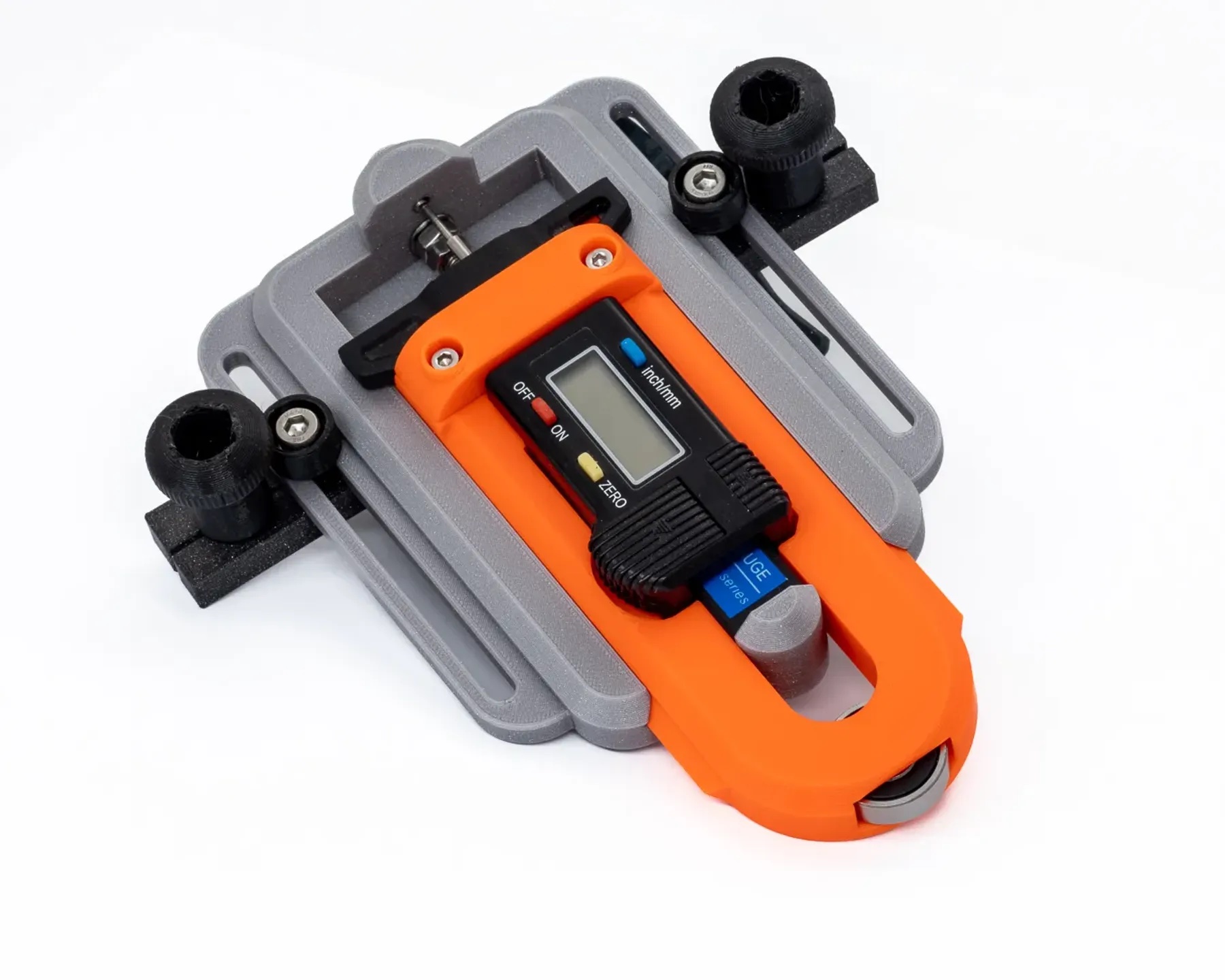
Before I go on - here’s a little something I prepared earlier that I probably wouldn’t bother using it in this instance because you don’t really need to be mm perfect but since you suggested it, another gratuitous link to one of my models can’t hurt
One of the things I’ve learned from fitting out boats is that unless you are making a fine jewel box or cabinet - if you can’t see the matching grain in the finished piece, there’s not a lot of point in spending time matching it.
I would have cut the “front” as you have, wihout the rebate in the back face, then cut the stock for the back to a consistent thickness, sanded and even finished before milling it.
I’d then cut the rebate in the back part with the cnc and depending on my mood, either cut the outline a mm or so oversize (probably what I’d do) and run around it with a flush trim bit after assembly, or cut it a mm undersize and call it done because it won’t be visible in the end.
Set up a stop block on the right side of the saw sled, 2mm away from the blade (thickness I needed).
This could probably be setup precisely using shims betwwen the blade and the block rather than measuring.
No need to re-adjust the fence or anything after each cut, just cut some slices like a ham machine
Thought for a sec about this possibility but there were several drawbacks
The main reason I added the rebate is not to locate the back piece, but to give more contact surface for the glue
Trimming the excess with a flush bit is definitely a great way to go, and you could indeed just roughly cut to size and then trim, but these are very light and flimsy parts, plus you’d have the “small” face lying on the table which is less stable… I’m not very confident in letting my finger so close to the router if I can avoid to
Just the harsh lazyness of setting up numerous tools At the moment, my router is not mounted under a table, the table saw is barely usable, cutting the rough pieces would probably require a band saw (which I don’t own) or a jig saw (which would again be quite finnicky for small parts)
I think the solution with the contour routed out on the CNC while I already have the CNC, bit and stock setup and secured + just a few cuts on the table saw sled is the best combination of simplicity and effectiveness
I don’t like that fixed stopper on the sled. There is quite a bit that can go wrong there (not that I haven’t done it)
I’d cut similarly with the scrap piece, but in the textbook position with the bit to be cut against the fence using a proper push block.
Apart from that - it doesn’t matter how the job is done as long as when it is finished you have the same number of fingers as when you started and the process has made you happy!
Yeah I know it’s bad practice to pinch the offcut between the blade and fence (or stop block here)
Things can go pretty wrong, almost got hit in the face with a chunk of 2x4 with this kind of setup in a mitter saw
But for this particular instance, I think the worst can happen is that the thin piece just get shattered if it gets caught
It would probably better to find a setup with a stop block for referencing the width of the cut reapitably, but not moving the stop block with the piece when cutting…
This could easily be done with a mitter gauge rather than the sled, but then you’d run the risk of the small part falling into the blade’s throat after the cut ^^"
Maybe a sled with a moving part on the left, and fixed part on the right?
Don’t think this would work, you’d still get a “free moving” part between the blade and stop block
This could even be worse. If the stop block is shorter then the piece you cut, the piece can still “escape” somehow rather than gatting constantly banged between the blade and stop block
i beg to differ, just as much as you love the journey of building more than using the actual thing you built, I’m often finding happiness in “how” you can approach a problem and find an adequat or optimal solution
I see these as small “riddles” along the way that just keep the brain enternained