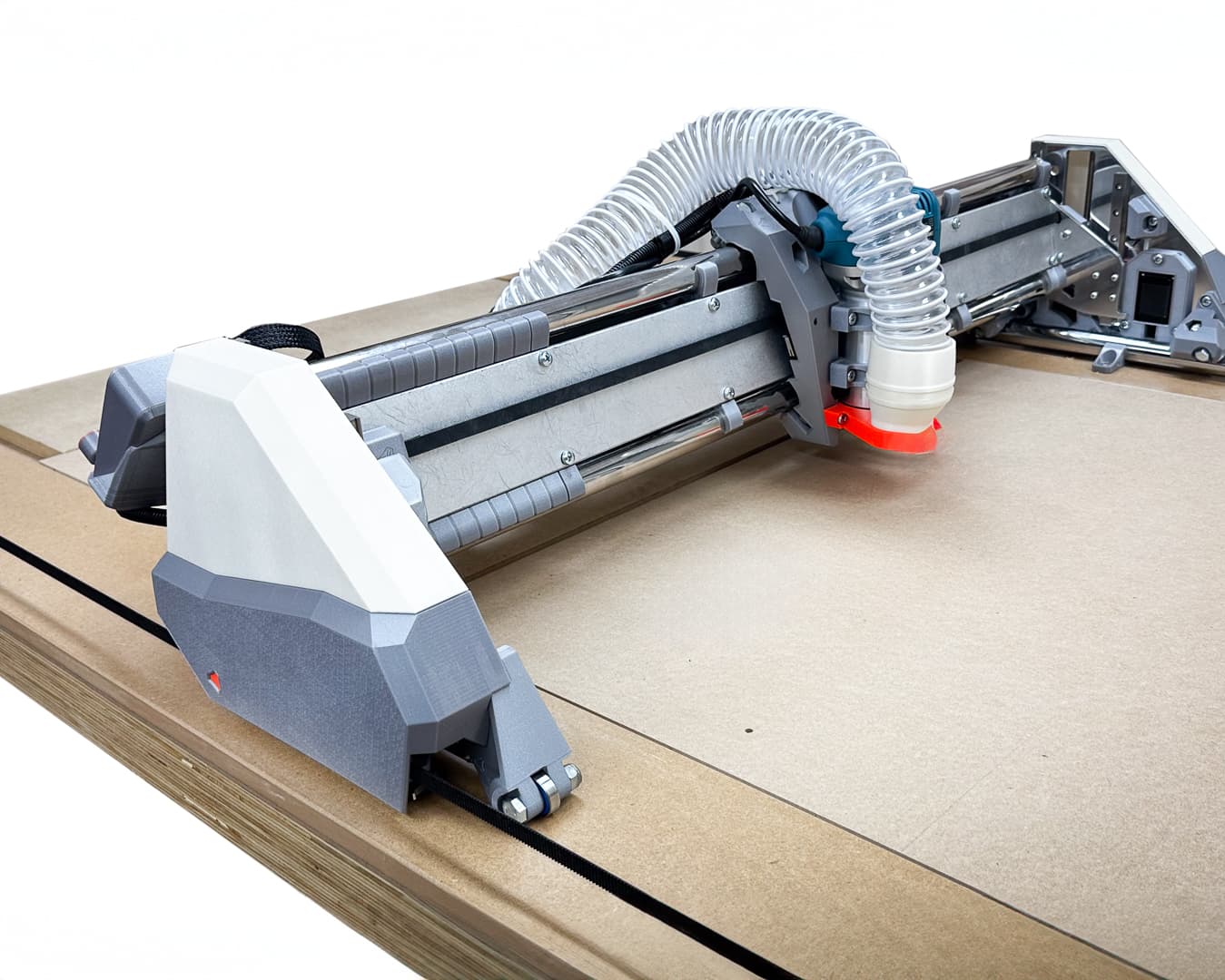
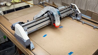
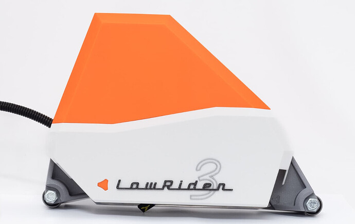
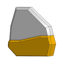
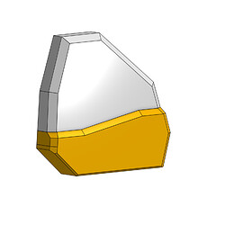
Here’s the current explanation text on Printables for comment/ critique or questions! I have to say it’s quite a relief to have actually got them out into the wild!
OVERVIEW
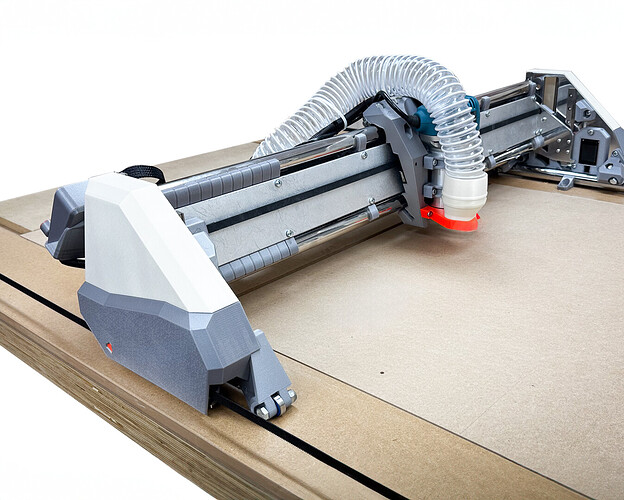
These fenders/covers were developed in the course of building my Lowrider3 CNC from V1Engineering.
They do not improve the operation of the Lowrider3 in any way, but if pretty is your thing perhaps you can convince yourself that they keep the dust and little fingers out of the moving parts.
The instructions below will possibly never be finished. I am yet to print the final clip version and will photograph the installation when I do - it only differs in small detail from the one I have operating in the photos.
I am happy to answer questions, make modifications and so on, and while I do check comments here and on the V1e Facebook group, the most efficient way to have your questions answered is to contact me via THIS THREAD at the V1e forum.
They are easy to print, no supports needed and I used PLA. Assembly is also not much more difficult than replacing a hub cap on a motor car, but there are some quirks which I will outline below.
INTRODUCTION
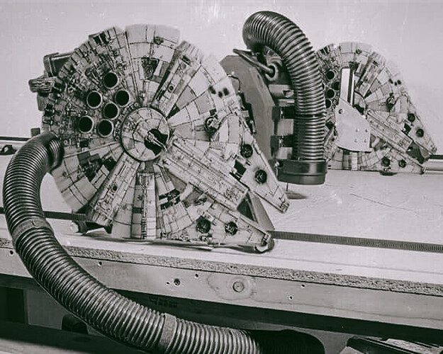
It all started as a bit of harmless fun that over the course of the year got just a little out of hand, here is my original concept from January 2023 perhaps some Enterprising person would like to adapt the current design :
My complete BUILD THREAD on the V1e forum is long and tedious, but one year later with a few sets of covers and clips in the bin, this is what I have in my shed.
PRINTING THE FENDERS
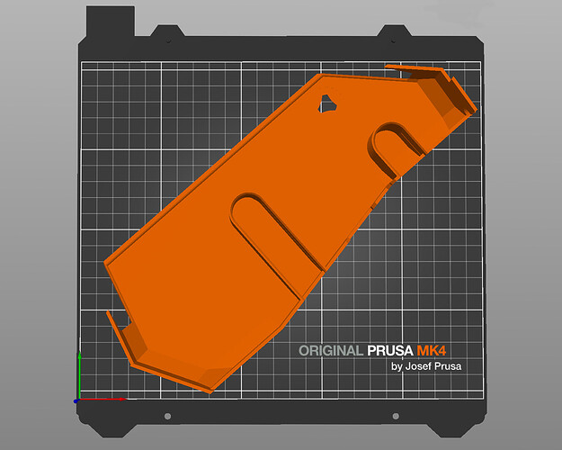
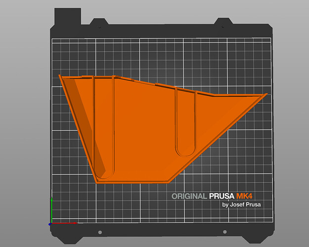
There are no real tricks to any of the parts - I’ve used “Hilbert Curve” bottom layers on the covers because that for me at least is a quite forgiving texture. The parts easily fit on a Prusa Mk3/4 build plate (250 x 210 build plate), no supports are needed.
I’ve used PLA, but I see no reason why any other filament couldn’t be used.
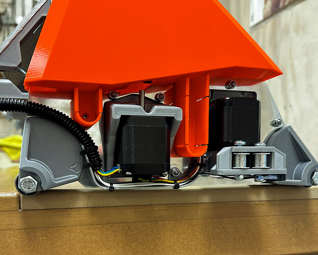
You can leave the little V1e logo cutout as is or print the infill piece and glue it from behind with a dab of super glue (as seen in the pictures above)
PRINTING THE SPACERS
The spacers are the only “Parametric” part - print in a thickness to suit your YZ plate thickness. The clips are designed to be 16mm from the inside surface of the plate, so if your plate is 16mm thick you don’t need a spacer.
To calculate the spacer size required simply subtract the thickness of your build plate from 16, i.e. if your plate is 12mm thick you will need a 4mm spacer.
I have provided a selection of spacers to fit common sizes. If you need something that’s not there it’s a simple matter of scaling the Z in your slicer to suit your required size.
PRINTING THE CLIPS
The detail of the clips included here has changed from the one I have tested, so until I have a chance to build and destroy a couple in testing, please take this as a sort of Beta print - it’s OK the big prints won’t change, and the clips are probably OK just not tested in their current form.
I prefer to use a minimum of four wall thicknesses and PLA - this gives a very (very!) stiff clip that sometimes takes a bit of effort to dislodge. Some may prefer to print them in PETG to give a softer spring, but I can’t vouch for their holding with a lot of vibration taking place. Thankfully they are simple to print and easy enough to replace.
ASSEMBLY
I will upload a sequence of assembly photographs in the near future - hopefully these notes are clear enough for the time being.
Cables
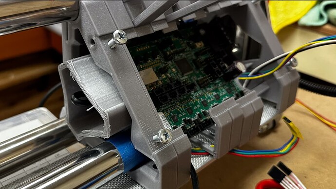
You won’t be able to use the cable tie holes built in to the standard parts, however if you tie them together neatly in a loom they will run logically and neatly. I have built a “cable tray” to secure them, which does a very neat job, but increases the fiddly nature of the task somewhat. I will upload that model once I am happy that it will work with thicker plate sizes.
Spacers
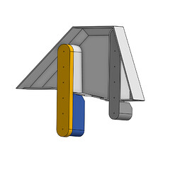
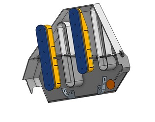
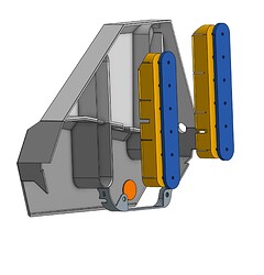
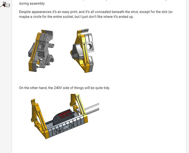
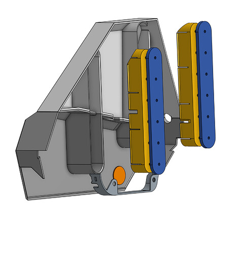
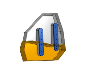
The spacers (blue in the above illustration) are used to adjust the clip offset to match the thickness of plate. Place them between the clip and the plate.
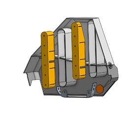
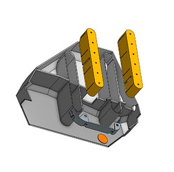
Clips
The holes in the clips line with the mounting holes in your linear rails. I have used longer M3 bolts and simply through bolted. This is a bit fiddly to do, is complete overkill, but you can be assured that everything aligns perfectly.
Alternatively there are a pair of 4.5mm holes in each spacer/clip so that you can screw fix them to the plate if you are using ply or MDF. If you do that, clip the top cover in place and locate it over the plate in position to accurately align the screw holes, drill, screw and repeat with the bottom cover in place.
The Fender Parts
These simply click into place, however like all simple things there is an easy way and a hard way. Best method is to hold the top and bottom together with the cable feeding through the exit and then work both of them onto the clips together.
A final bump to snap them into place should be all that is needed.
![]()
