MP3DP v4 - Aza's build

@gpagnozzi @probrwr and any other MP3DP v3/V4 folks using Klipper.

Are you using z_tilt and/or Bed Mesh to probe/level/calibrate your beds before printing?

Curious if z_tilt works for others. Currently digging thru klipper code tracing/debugging z_tilt, so feels like I must be missing something simple. Cheers!

1 Like

Z-Tilt on every print.
And call the saved “ Default “ bed mesh.

Once you do the initial setup, z-tilt and save the bed mesh, you don’t need to do bed mesh before every print. Just the z-tilt.
I’m not home to post my current print.cfg but if you look at the one I posted couple months back you can see that start print section call for the z-tilt and the saved bed mesh.

2 Likes

Nice! Thanks for the info @gpagnozzi, really appreciate confirmation that [z_tilt] is expected to work.

Your post helped me take another look at my setup and wiring again… Turns out I’d messed up the wiring and plugged one of the steppers into motor2_2 :man_facepalming:, instead of skipping, similar to what we do for SKR1.2 Pro.

Fixed and finally have z_tilt working now :slight_smile: Here’s the stepper wiring that’s working for me…

Seems to take z-tilt 6 attempts to satisfy the retry_tolerance: 0.005 value. Am double checking distances/dimensions of my pivot points to see if that helps. Also moving probe positions as close as possible to pivot points should help.

Even so, I (a Klipper Noob) don’t understand why 0.005 tolerance is needed given the 0.645mm variance observed for my Alu plate. Measured at room temp, no PEI/magnetic layer yet, bought from amzn. Probably not Cast Alu, which I learned would have been more stable during hot-cold cycles. I may also have warped the plate further when cutting down to size with angle grinder. Am still learning what mesh variance most people find acceptable?

Looking at ways to speed up since z-tilt is needed before each print. e.g. Sleep intervals between probe readings seem unnecessarily long (~1s), looking into that too…

Am loosening retry_tolerance: to 0.04 for now until I learn better, and/or someone informs me? Tolerance of 0.04 is helping z-tilt process complete faster with just ~2 attempts.

Cheers!

2 Likes

Z2 port should have jumpers it is wired in series. It should not work without them.

1 Like

0.04mm across a 250mm bed is very good in my opinion. Make sure to let the bed heat soak for a few minutes to stabilize beofre leveling, make sure it has a bit of room to grow and shrink.

2 Likes

Thanks Ryan, currently heating the bed 60C for ~10mins. Will then z-tilt and mesh calibrate again. Curious to see how much warp occurs…

Update: Getting similar result with or without heat. Don’t know what kind of tolerances others are working to? Guessing high/low spots are due to mix of Alu plate, gantry, surrounding frame, other factors…

Ideally, within reason, I wouldn’t care about the cause, providing the cause and result were consistent, and could be compensated for… Maybe pouring/printing a very thin leveling layer between the Alu and the PEI’s adhesive magnetic layer would help smooth out. “Bed shim generator”, bad idea, or been done already? Briefly thought about using my LR3 to surface Alu plate, but doubtful on accuracy, also, Alu plate may not be most significant cause.

Update #2: Dug around, looks like most people would be happy with measured variance of ~0.3mm or smaller. Some notes and links to things people explored :

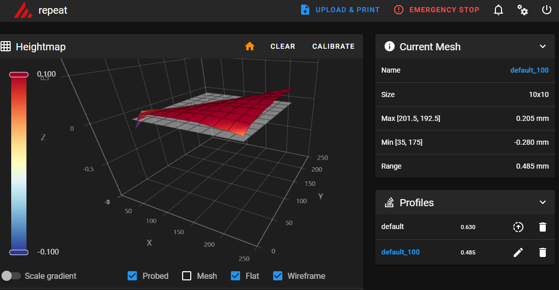
Update #3: Tried adjusting rails/gantry, getting pivot points close to 0 variance, but the rear loose corners are way off (rear left corner low, rear right corner high). Getting overall Meh variance of ~0.6mm.

Will be using calibrated mesh profiles during prints to reduce impact of bed variance. However… Will probably try out Ryan’s/someone’s suggestion to reduce variance using Blue Tape and/or Kapton Tape as shims. Will add patch work of tape on magnetic layer, under the PEI coated spring metal.

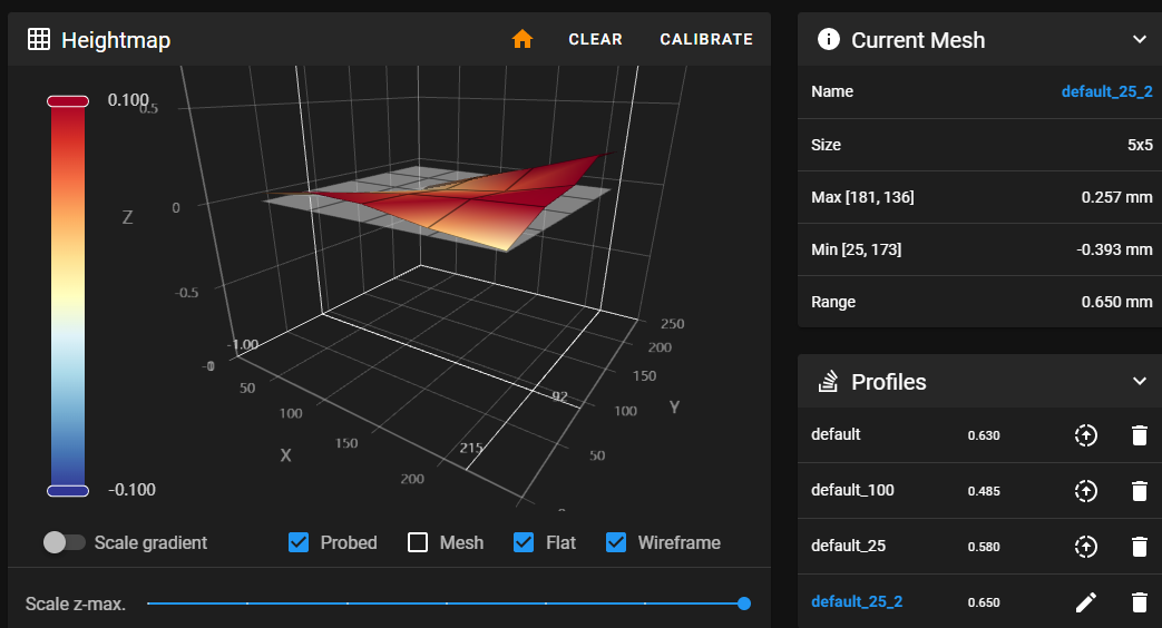
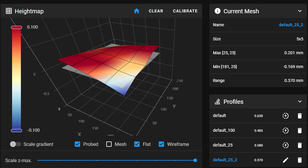
Update #4: Tried z-tilt with 4 corner probe points instead of 3 near the pivot points. Relaxed tolerance as well. Goal was to ensure twisted Alu plate corners are considered by z-tilt, and split the difference finding an orientation that results mesh calibration finding least overall variance. Doing this ended up better variance of ~0.37mm instead Meh ~0.645. Seems good enough to me. Suggestions appreciated, but planning to move onto next step…

Was using [z_tilt] with 3 probe points near Z post pivots…

points: 25, 55
  150, 240
  245, 55

Changing to 4 probe points with lower z-tilt tolerance resulted in better overall variance.

[z_tilt] #AZA https://www.klipper3d.org/Config_Reference.html?h=pixel#z_tilt
z_positions: -20, 27
  135, 303
  292, 27

points: 25, 55
  25, 240
  245, 240
  245, 55
speed: 150
horizontal_move_z: 10
retries: 10
retry_tolerance: 0.1 # was 0.04, default 0.005

Pending…

Cheers!

2 Likes

Mic6 is 0.381mm…I’d say 0.4mm is about as good as you could expect. McMaster-Carr

2 Likes

While trying to minimize bed variance… Made a simple shim to help keep linear rails parallel to extrusion. Assuming extrusion is straight and framed accurately… My thinking was this’d help (marginally) limit variance from being contributed by avoiding skewed linear rails.

shim-lip-4mm.zip (19.7 KB)

Spent some time adjusting the belt tension to try and square the gantry, still doesn’t look/feel right to me, will keep tinkering…

2 Likes

I have a rail aligner piece in the file stack. What isn’t feeling right?

3 Likes

This is what I used when i put mine together and it worked well.

3 Likes

Was curious about impact of PEI on height variance while reading Jonathan’s topic. So, jankily temporarily taped PEI and magnetic layer to Alu plate…

Used 4 point probing for z-tilt (instead of 3, details provided in earlier post), to help split the difference in my minor twisted setup…

Not seeing much difference relative to previous mesh calibrations.

Measured extrusion diagonals between corners, looked the same to me using a regular mm based tape measure. Double checked extrusion is straight too. All looks good enough to me, leaving things as is and moving on. Hope this info helps someone.

Longer term, after seeing Prusa XL at RMRRF, am curious whether linear rails on top of the extrusion would enable easier shimming/adjustments of linear rails to easily compensate for skewed/twisted frame cuts/assembly inaccuracies? Could gain additional X width too, but maybe that approach would introduce other motion challenges?

image

1 Like

That just moves the adjustments to a different plane.

Going to the top moves everything related to XY, that also drags the Z up as well. From messing with it I did not see any advantages, unless I built a mostly metal version.

I am not really sure how I feel about the printers. For the number of builds out there, there seem to be a lot of struggles. It takes me a while to get mine dialed in but I am shooting for pretty extreme accuracy.
I am wondering if my version is fit for a wide release like this. I have nothing to compare it to, but the feedback seems to be 50/50 right now.

1 Like

All three of us have the same direction of twist?

I have a 0.4 overall twist on a smaller bed so yours is more accurate than mine. With level fading that is easily compensated for in a few mm worth of print height.

2 Likes

Is there a badge for the most twist??? If so I think I win that one!!

Couldn’t resist seeing if/how laser could help…

Wondered whether observing height of the laser on the hotend, and surrounding parts during moves will help isolate what needs tuning.

Note, was using a makeshift tripod, and the bench was not true level, let alone a true flat surface. Kitchen countertop (verified with a level) would have been a better surface to use.

Ideally would’ve used better quality more finely focused laser, this one’s ~10yrs old.

Ignore the right rear corner where the PEI had uplifted slightly.

The laser helped me eyeball observe small height differences where laser hits the hotend. These differences mostly correlated with the mesh. So, this info would help me focus on tuning that if I already figured my Alu/Bed surface was flat enough.

Am happy with my setup, but IF the height variance was unacceptable and seemed to be caused by rail skew/twist, thinking I’d use this approach to help figure out which Y linear rails to loosen, adjust and snug back up. Improvements/suggestions appreciated, this is new to me. Cheers!

2 Likes

When I build mine I measure every diagonal I can and keep adjusting until I get it as close as possible. I make sure all my rails are centered.

After that, I do the belt tensioning to get the XY prints square. After that, I do the Z prints to get the Y rails parallel. That adjustment is just letting the rails move down or loosening the screws or push them up. The screws give a ±1.5mm each way I would guess. So that lets you move one rail up and the other rail down for a full 3mm of angle or so. Typically I end up only needing to move one rail up or down and that gets me a very square cube.

So spend all your time with the frame and the diagonals. Then the test prints bring it in the last faction of a mm.

It took me a long time to figure out the adjustments but I was super concerned about a twisted or skewed Z system but it seems the three rails kinda balance each other out. So once it’s built I believe we end up tuning the Y rails to the Z system, not actually to the frame.

I guess I should look at how the Voron guys have the frame calibrations set up.

2 Likes

No more issues for you anymore?

1 Like

No more issues since you mentioned Mic6 is 0.381mm, cheers for that!

Am not fixing anything that needs fixing, am just tinkering and learning. Sorry for randomizing :slightly_smiling_face:

2 Likes

I think the best way to use the laser would be to turn off the leveling feature and just mark two equal points on the frame so there is no chance of the level actually being the issue.

It is the best idea yet, it is hard to measure something with no solid frame of reference.

1 Like

No no, glad to hear it.