MP3DP V4 build PLOG


p
Going super slow, and trying to keep everything neat, and it still turns out like this… A few zip ties will help make it a bit more presentable, I guess, but I’m a little bummed out that it doesn’t look nicer.

Obviously neat wiring is not my strong suit…

Almost done the basics though. I still need to wire in the 5V power for the ESP32cam and do the new plug for the extruder motor. I will also make a protective cover for the Duet, once I get things together.

On the good side, I can just put the PT1000 sensor in the hotend now. This will let me extend the temperature range for printing stuff like PC or Nylon if/when I decide to try it.

I need a holder for the PTFE tube to feed the filament, I guess.

Still to do is mate 2 of the Z motor wiring harnesses. This will happen on the underside of the bed support.

My 10x10 drag chain is a little tight. I should have gone for the 15x10 chain. I think there is still a possibility to swap them. The biggest issue is the 18AWG wire that I used for the stepper motors. This is what the Duet wiring guide suggests for the lugs. Makes sense, those drivers are good to 3600mA, I think. Enough to pop those stepper motors for sure, and probably run some higher torque NEMA23 motors. Makes me think I might take another look at some of those Joe’s CNC machines.

I think I have the base machine configuration down in RepRap Firmware. Still not sure that I have the BLtouch set up right. So far, my homing sequence turns down the motor current to 25% (200mA) and then homes to the bottom extreme, but I don’t have the sequence for probing to level the bed. I have the motor (Well, the 5mm support bolts anyway) positions defined, so I should be able to probe near each motor and come up with a very close approximation to level.

Hopefully by tomorrow, I’ll have the machine moving.

3 Likes

Getting closer!!! Better hurry im catching up to you LOL

I couldnt have said this better!!! Im going to do my best but probably wont end up as neat as you have yours much less how i would like it to actually be. Im still trying to figure out which board i want to go with and what firmware. Half of me wants to run the SKR pro i have from the LR3 and Ryans marlin firmware. The other half of me wants to run the Octopus Pro 1.0 i bought and Klipper firmware. I just cant make up my mind which way to go. Need to soon though. I’m about to glue on the bed heater and PEI sheet…so wiring is next!

I think the ley to wire mgmt is to just have a place to hide the sins. I can never make the cables the perfect length. That said, I always think I can do better and it never affects performance.

1 Like


It’s upside down because I’m working on the Z motor wiring under the build plate, but a few zip ties make it look a little better. I’m undecided if zip ties are the greatest thing ever for wiring because it can turn an unruly mess into a wiring harness, or if they’re true evil because of the multitude of sins that they can hide…

This is almost complete. I still want to add the 5VDC for the ESP32 camera, and of course as soon as I zip tied it all up, my PT1000 sensors showed up. I think I’ll run it with the thermistor for a while…

As soon as I get the motor 1 and 2 wires soldered up it will be ready to move. I think I have all of the firmware sorted put and configured. I stole the steps/mm for the Hemera from the current value for my Repeat, should be close enough for another Hemera to start.

I’m missing a V1 sticker for the front :frowning: I thought I’d ordered another one, but looking at my order history, I guess I didn’t. Well, I’ll need to make another store order at some point, so it’ll have to wait.

:rofl:

Okay, so some unforseen issues.

  1. My fans don’t work. Neither does the LED lighting. Something there isn’t happy, and I don’t know why.

  2. My BLTouch is … weird. It sort of works, I can probe the bed, but I can’t use if for motor adjustment. I have the motors defined, and their positions, but it just refuses to actually probe the bed if I’m saving the positions for bed levelling.

  3. The height map is … well, honestly better than I expected given that I can’t do bed levelling. It’s basically going off of the sensorless homing to the bottom position (Which takes a lot of skipping before it triggers.) The good news is that the BLTouch works for G29.
    Height Map

I managed to get the X and Y motors wired backwards. I adjusted them in firmware. The Z motors were OK. I don’t know about the extruder because I haven’t heated it up since the fans aren’t working.

Configuration files (Please note this is still incomplete, but might help if other people want to use RepRap Firmware.
config.g:

; Configuration file for Duet 3 MB 6HC (firmware version 3.3)
; executed by the firmware on start-up
;
; generated by RepRapFirmware Configuration Tool v3.3.15 on Tue Feb 21 2023 20:05:02 GMT-0800 (Pacific Standard Time)

; General preferences
G90                                          ; send absolute coordinates...
M83                                          ; ...but relative extruder moves
M550 P"DMG3D03"                              ; set printer name
M669 K1                                      ; select CoreXY mode

; Network
M552 P0.0.0.0 S1                             ; enable network and acquire dynamic address via DHCP
M586 P0 S1                                   ; enable HTTP
M586 P1 S0                                   ; disable FTP
M586 P2 S0                                   ; disable Telnet

; Drives
M569 P0.0 S0                                 ; physical drive 0.0 goes backwards
M569 P0.1 S0                                 ; physical drive 0.1 goes backwards
M569 P0.2 S1                                 ; physical drive 0.2 goes forwards
M569 P0.3 S1                                 ; physical drive 0.3 goes forwards
M569 P0.4 S1                                 ; physical drive 0.4 goes forwards
M569 P0.5 S1                                 ; physical drive 0.5 goes forwards
M584 X0.0 Y0.1 Z0.2:0.3:0.4 E0.5             ; set drive mapping
M350 X16 Y16 Z16 E16 I1                      ; configure microstepping with interpolation
M92 X100.00 Y100.00 Z100.00 E395.45          ; set steps per mm
M566 X900.00 Y900.00 Z60.00 E120.00          ; set maximum instantaneous speed changes (mm/min)
M203 X9000.00 Y9000.00 Z3000.00 E2700.00     ; set maximum speeds (mm/min)
M201 X3000.00 Y3000.00 Z1500.00 E3000.00     ; set accelerations (mm/s^2)
M906 X800 Y800 Z800 E800 I30                 ; set motor currents (mA) and motor idle factor in per cent
M84 S60                                      ; Set idle timeout

; Axis Limits
M208 X-15 Y0 Z0 S1                           ; set axis minima
M208 X235 Y250 Z243 S0                       ; set axis maxima
M671 X-30.3:276.3:222.5 Y34.5:34.5:307.8 S5  ; Motor positions: -30.3,34.5; 276.3,34.5; 222.5,307.8

; Endstops
M574 X1 S1 P"^io0.in"                        ; configure switch-type (e.g. microswitch) endstop for low end on X via pin ^io0.in
M574 Y1 S1 P"^io1.in"                        ; configure switch-type (e.g. microswitch) endstop for low end on Y via pin ^io1.in
M574 Z2 S3                                   ; configure sensorless endstop for high end on Z

; Z-Probe
M950 S0 C"io4.out"                           ; create servo pin 0 for BLTouch
M558 P9 C"io4.in" H5 F120 T6000              ; set Z probe type to bltouch and the dive height + speeds
G31 P500 X0 Y-36 Z2.5                        ; set Z probe trigger value, offset and trigger height
M557 X15:195 Y15:195 S20                     ; define mesh grid

; Heaters
M308 S0 P"temp0" Y"thermistor" T100000 B4138 ; configure sensor 0 as thermistor on pin temp0
M950 H0 C"out0" T0                           ; create bed heater output on out0 and map it to sensor 0
M307 H0 B0 S1.00                             ; disable bang-bang mode for the bed heater and set PWM limit
M307 H0 R0.155 D15.47                        ; set PID parameters for heated bed
M140 H0                                      ; map heated bed to heater 0
M143 H0 S120                                 ; set temperature limit for heater 0 to 120C
M308 S1 P"temp1" Y"thermistor" T100000 B4138 ; configure sensor 1 as thermistor on pin temp1
M950 H1 C"out1" T1                           ; create nozzle heater output on out1 and map it to sensor 1
M307 H1 B0 S1.00                             ; disable bang-bang mode for heater  and set PWM limit
M143 H1 S280                                 ; set temperature limit for heater 1 to 280C

; Fans
M950 F0 C"out7" Q500                         ; create fan 0 on pin out7 and set its frequency
M106 P0 S0 H1 T45                            ; set fan 0 value. Thermostatic control is turned on
M950 F1 C"out8" Q500                         ; create fan 1 on pin out8 and set its frequency
M106 P1 S1 H-1                               ; set fan 1 value. Thermostatic control is turned off

; Tools
M563 P0 S"Hemera" D0 H1 F0:1                 ; define tool 0
G10 P0 X0 Y0 Z0                              ; set tool 0 axis offsets
G10 P0 R0 S0                                 ; set initial tool 0 active and standby temperatures to 0C

; Custom settings are not defined

; Miscellaneous
T0                                           ; select first tool
1 Like

Okay, I figured out the BLTouch issue. Missing a parameter. Now with the Z motors level, the bed map looks a little cooler. Obviously not as flat as it could be, but good enough for the girls I go with…
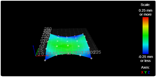
Height Map

G29
25 points probed, min error -0.360, max error 0.020, mean -0.138, deviation 0.109
Height map saved to file 0:/sys/heightmap.csv

Edit: Where the low points are is close to where the screws are, so maybe they’re a bit too tight. Most of the bed looks pretty good, and the whole point of this printer is for smaller footprint items anyway. If anything were to be close to the edge, I’d use the first Repeat with the 300mm print bed.

1 Like

I’ll give you one at Rmrrf if you can make it!?!

That is how that sentence should work.

I don’t think you would have a problem with it, the mesh leveling should take care of it. Loosen those holding screws a touch and I bet those numbers get closer to Barry’s Ultra flat bed.

1 Like

Yeah, loosening those is a bit of an issue. I can deal with it if needed, I suppose, but since I put the magnetic sheet over the heated platform, getting to the screw heads isn’t convenient, so I don’t want to do it if I don’t have to. Mesh levelling will take care of it, and even if not, it’s about 1/4mm down in the low spots.

One thing that amazes me is how much faster the Duet manages the G29 procedure. The first one where it mapped a 10x10 grid (100 points) took less time than the Repeat does with a 7x7 grid (49 points) I thought it might be my imagination, so I ran them side by side, and this printer gets it done faster. The combination of a lower dive height and no settling pause before probing. I can configure a settling pause, but it doesn’t seem to be necessary, and I like the speed.

The G34 is kind of missed though. Because the motor positions are defined, it is supposed to be able to level the bed in one shot. For some reason, it seems to be not quite perfect in one go. It leaves about 0.1mm discrepancy after one pass (From about 0.35mm after homing to the low position with motor stall detection (Which is now working, since I bumped up the sensitivity.)

Fortunately, RepRap Firmware supports looping structures, so I can just run the bed levelling more times. 1 run leaves about 0.1mm, 2 runs leaves about 0.03, and 3 runs reports 0.009, which is closer than the nominal motor steps. This is fairly consistent, even if I put an obstacle under one of the motors to force it to be further out of step.

Printing soon™

1 Like

Are you mapping the steppers to the center of the plate screw hole, or the rail? Should be the screw hole. That bed offset might be something that has not been tested much before, maybe the math is a bit off? I feel like most printers do things symmetrical.

1 Like

Yes, I am mapping them to the center of the screw hole, I took the coordinates relative to the front left screw from the bed plate, measured on the DXF sketch.

The RRF bed levelling is supposed to use probe locations “close to” the motor locations, but they don’t need to be equidistant. (Would be difficult for the back motor, for example.) the fact that it is so close after the first adjustment tells me that it’s pretty good, I think. Might be some “drawing versus real world” involved as well.

1 Like

My printer usually gets it within three tries, almost never on the first go though.

1 Like

Wow. I managed to get exactly nothing done on this all weekend.

I need to get the fans sorted out, at the very least the hotend cooling fan, if not the part fan. For some reason thise are not coming on.

The 12V LED lights are working, but the part cooling fan and the hitend fan are 24V. I got 24V from the +Vin fan pins, but no ground from the switched pins. Maybe I’ll just wire the hotend fan to 24V so that I can make sure that I have the extruder running forwards, and dial in steps/mm

The one last thing that I need to do for the printer itself is print a retaining clip for the filament guide tube.

The hold-up is that I need to find a home for it in reach of an ethernet switch… The Duet 6HC is wired ethernet, not Wifi. The living room has been declared off limits. I think it will fit on a 19" rack shelf… as soon as I get one cleared off. Hmmm. Rack mount 3D printers…

Edit: crap. 450mm between the posts, and the printer is 460mm wide at the aluminum frame, 472mm wide at the plywood. I think I can still get it on a shelf behind the posts. It would fit rather well with the standard 200mm X dimension at 410mm across the aluminum frame. Then the front face could have a slight “wing” to it bringing it out enough to screw into the rack frame. Thst would be great for a print farm, which I seem to have and absolutely 100% do not need.

2 Likes

Where did the week go?

The plan this weekend is to get this printer going. Something is weird with the fans.

There are 2 banks for fan power, both selectable for Vin or 12V where Vin can be up to 36V (I am using 24V.) Bank 1 is configured for 12V so that I can use it with the LEDs. This seems to work, and the lights turn on when bed temp hits 35°C to full brightness st 60°C this is probably unnecessary, Im just having some fun with it. This bank uses 4 pin wiring, wirh xonstant power, a tachometer and PWM control. The lights go from power to PWM.

The second bank is 2 wire, and configured for Vin. I verified that I have +24V relative to ground, but the PWM ground pin doesn’t seem to work.

Possibilities are that I have something buggered on the board and no ground to the MOSFETs, or somehow selected the wrong control pins for the fans.

If it’s the former, I guess I can use the same strategy, wire the fans to bank 1 on power and PWM. It requires an oddish connector that way, but the lights prove that it works at least. This will mean losing thermoststic control of the lighting, but that’s not too horrible. I have other places I can get +12V from at least.

If it’s the latter (I’d rather this be it) then I need to figure out what those pins actually are (and maybe which ones I’ve been switching…)

2 Likes


Currently printing its first object (the end for the filament guide tube.)

Printing in ABS because I had some lying around where it sits. This is away from where the other printers sit because I needed an actual network cable :blush: .

Edit: print #1 lucky the extruder motor goes the right way! No tuning of steps/mm on the Hemera so I was a bit nervous. I forgot how bad ABS smells when printing…

3 Likes

It’s ALIVE!!!

I was messing with some side plates for my next build this morning. Very interested to see what you think of this one.

1 Like

It is nowhere near as loud as I’d feared that it would be. Or at least it wasn’t until I put it on an Ikea LACK end table in my closet. Even then, what makes the noise is the Z axis, so it’s not that bad.

Moving it around, it’s solid as a rock. everything feels way more solid with the panels on. It looks nice, and there are places for things like the power entry. I’d definitely do it again.

Edit: And it shows what the humidity is like around here. that ABS filament has been sitting unwrapped for probably 5 years. (Maybe more, but it was about 5 years ago that I would have hung it up in the closet.) Sometimes I think the filament dries out more being unwrapped here, particularly in the wintertime.

1 Like

Okay, I got around to programming the ESP32Cam for monitoring printing.

As soon as it powered on, the little red light on the serial FTDI came on, and it got someone’s attention…

… No, that’s the wrong little red dot…

2 Likes

And, just for completeness, another cat picture… Print #2


6 layers/mm, printed in ABS for the same reasons as the first print. Gotta get it out of my bedroom, it shakes this poor little Ikea table like crazy…

3 Likes

3 wall, 30% gyroid infill ?

Edit: Just found guidance for v3 printed parts, MP3DP v3 Parts - V1 Engineering Documentation, will follow that for now…

  • “Infill on the parts is not a big deal I use 20%+ will be fine 40% is really nice, but make sure to use 2-3 perimeter walls to keep the through hole support.”

23-03-14 Edit: Ended up using 3 wall, 35% cubic. Didn’t like how much gyroid infill pattern was rattling and slinging the bed around (Ender 3 Max).

1 Like

Yeah 40% is probably really good.

1 Like