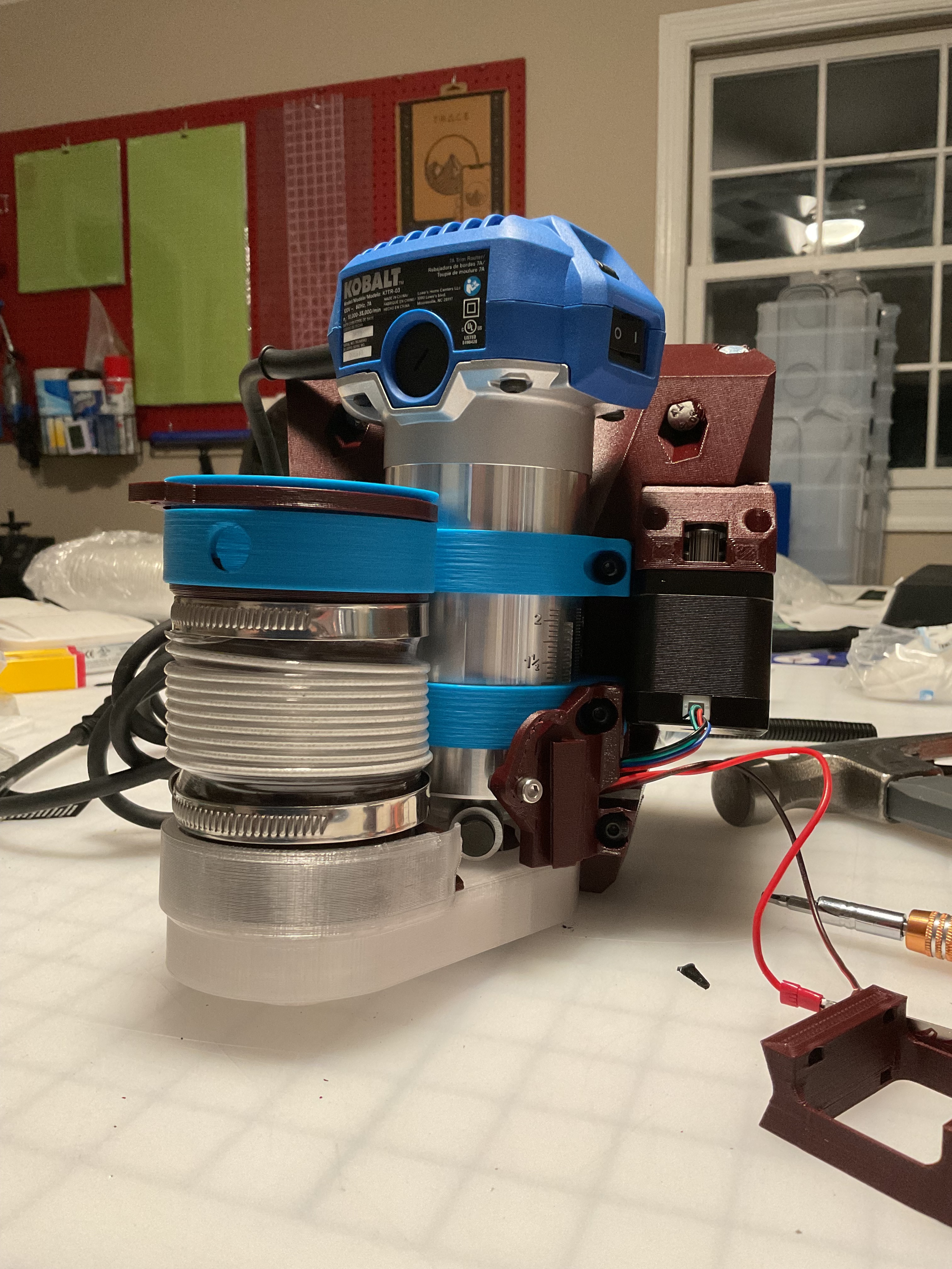
Got the core done… where does one put the tiny touch plate??
2 Likes
I tuck mine between the router and the core.
Like in this post - I messed up, but fixed it - Marble Solitaire
Excellent mod! Can you please share the print file, or even better, would you be able to share the F360 source file? I may want to move the belt even closer (about 10-15mm), so I can use it on the rail side of my build
@Fabien’s V2 fits perfectly for the non-rail side
But for the rail side, it sticks out way too far…
and I would need to move the rail in about 40mm (losing some table space and cutting area)…
It looks like your version would solve that issue, especially if it is in any way parametric/adjustable.
Edit - never mind, I see that you posted in in Github a few months ago in post #159…
1 Like
Ah yup, not parametric, although I really should make it parametric and adjustable.
But hope you find what you need with it, has been working flawlessly for me! I can help tweak if you need help, i think the adjustments I’ve made I just split on the surface the stepper rests on and moved it in and out and then fudged the pieces around it to fit comfortably after joining. Not my cleanest work, but hey it’s on the table and cutting stuff!
1 Like
If you are offering, I would be very grateful!!! My F360 skills are rudimentary at best, and I’m not sure how to go about modifying the STEP file that you put on Github. (I know what I want to do, I just don’t know how to do it… yet.)
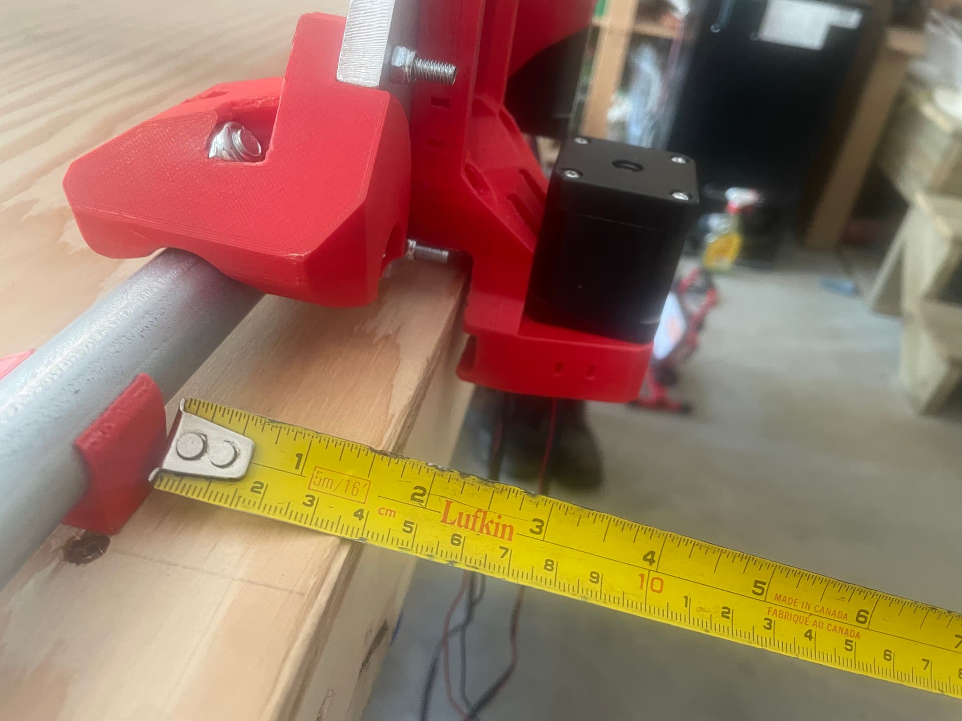
Currently your design has the edge of the belt roller housing at 7.3mm outside of the outer edge of the YZ Plate.
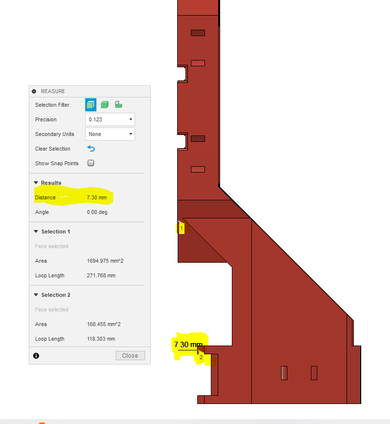
In an ideal world, I would like to have my Y rail holders align with the edge of the table. That would put the inner edge of the YZ Plate about 12mm away from the table edge.
The YZ Plate is 9.7mm thick, which puts the outer edge of the plate at a shade under 22mm away from the edge of the table.
,
I’m not sure how far away the belt sits from the table edge, (probably 3-5mm?), so I’m thinking that if the edge of the roller holder was 15mm in from the outer YZ Plate (22mm closer than it is now), that would be pretty close to where I want it, and any extra I can make up by sliding the rail towards the center of the table a couple of mm if needed.
This might need to have the motor mount portion move so that the inner edge of the motor is just flush with the outer edge of the YZ Plate, and it also might require extending the roller axis (and switch mounting holes) further away from the pulley. Both of those tasks are beyond my current skill set.
1 Like
I provided the f3d file on my version and it’s parametric
https://www.printables.com/fr/model/600688-lowrider-3-cnc-side-mounted-y-belt-v2/files
Bartman’s version is a bit simpler and stiffer (in fact I’m using his version), but I don’t have too much time right now to include his modifications in my design
Feel free to edit the f3d and re-post a remix on printables
3 Likes
My version is essentially a remix of Fabien’s motor arm, he did all the leg work. Mine is just tweaked a bit for my liking but mainly my github was for the belt holders. You might be able to get better results with his if it’s parametric (I can’t remember actually, I’m sure I remixed it the hard way haha)
But if that doesn’t work I can find some time to mod mine for you within reason. I did have a hard time following your message visually, do you have a pic of the edge of your table? I see you said bring it in 22mm but that seems like quite a bit haha I can try to do that for you if you’d like but I’m just really curious the table’s edge you’re working with
1 Like
Thanks for providing that file. I used it on the non-rail side, and it worked perfectly!
Unfortunately if you try to reduce the table distance below 20mm, the model fails…,
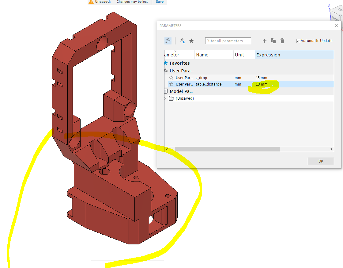
Negative numbers (which I effectively need) are simply ignored.
Yes, the issue I think is that @Fabien’s and your designs were created for use on the non-rail side. I am trying to adapt it for use on the rail side. If I use @Fabien’s design at it’s smallest available parameter(20mm), the rail would have to be inset 40mm from the table edge. Your design is about 11mm closer, but that still would require the rail to be 29mm from the edge.
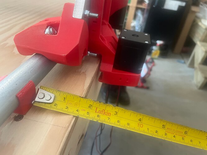
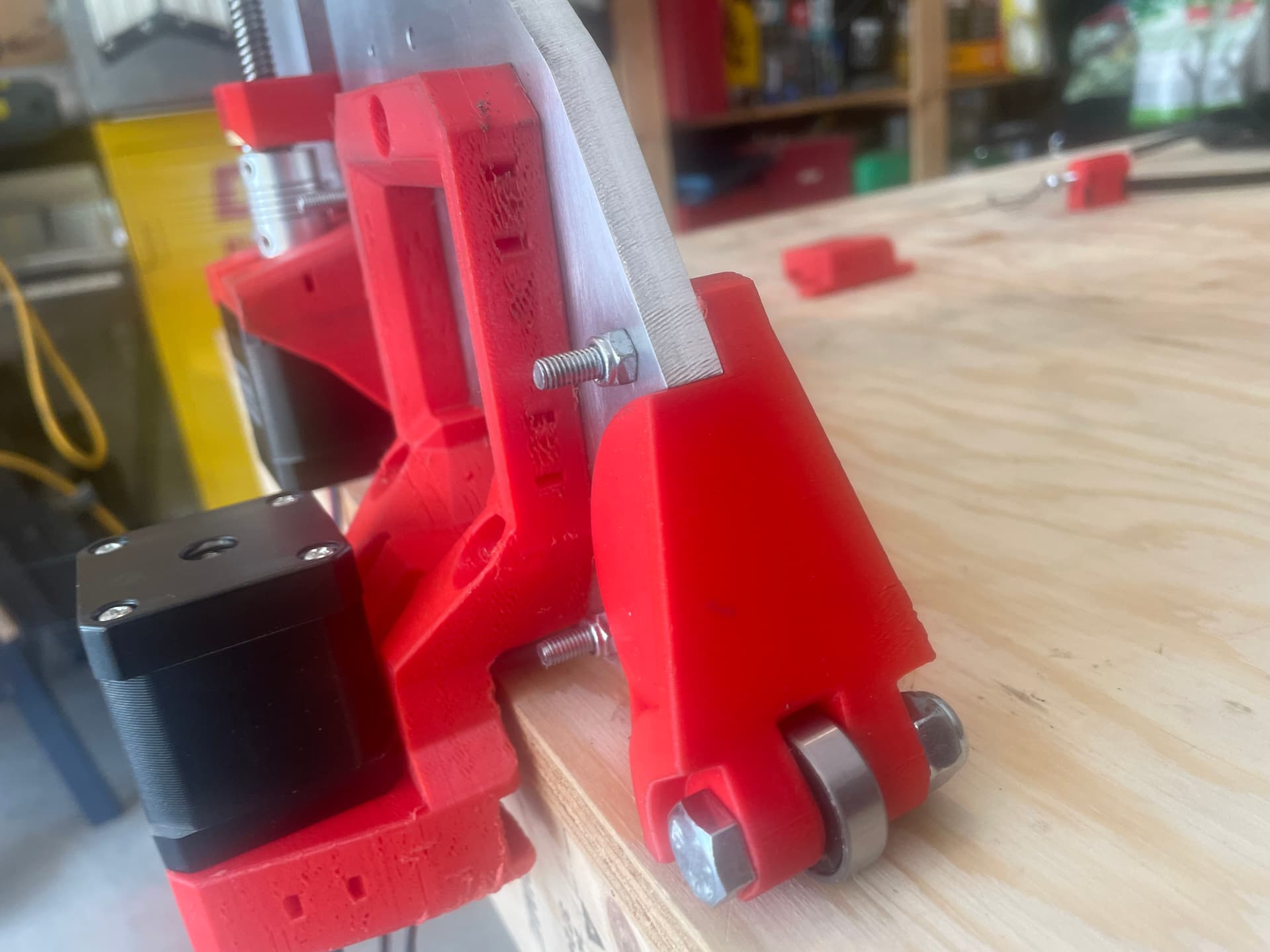
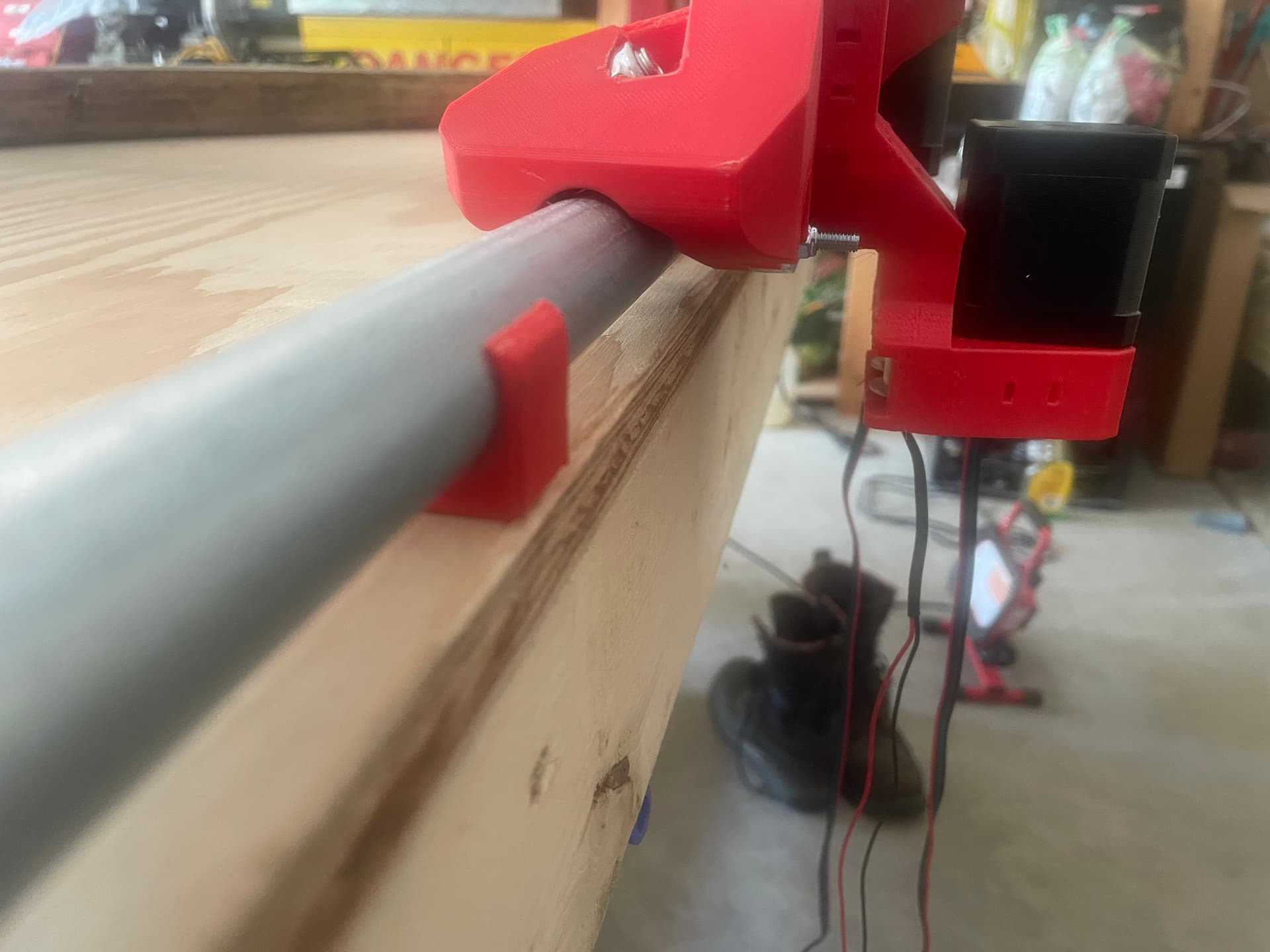
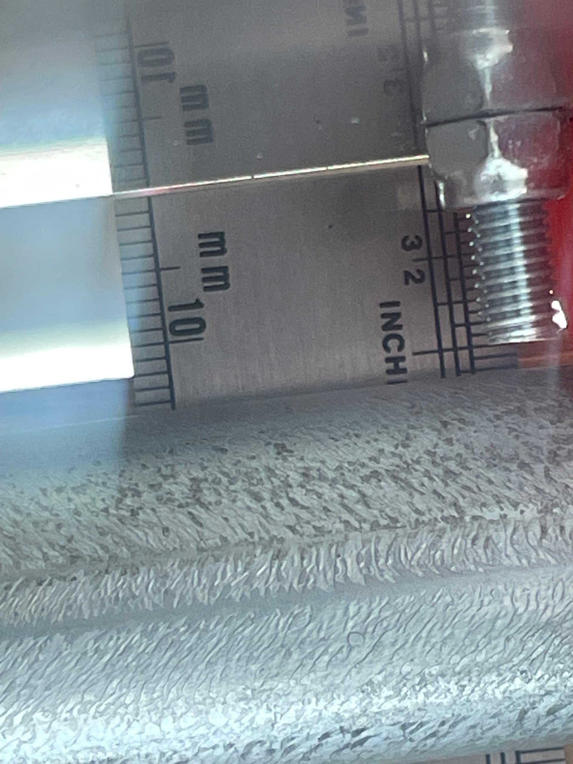
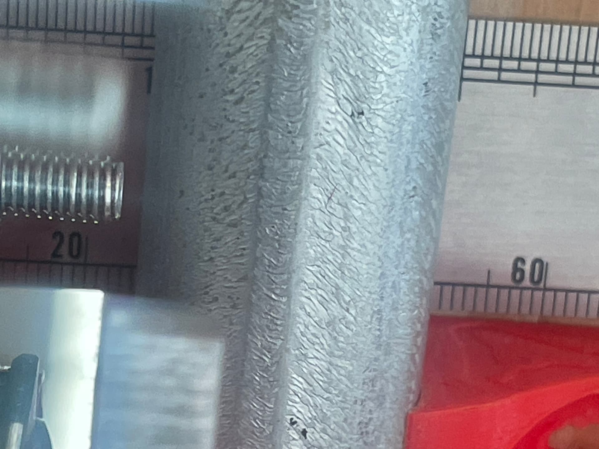
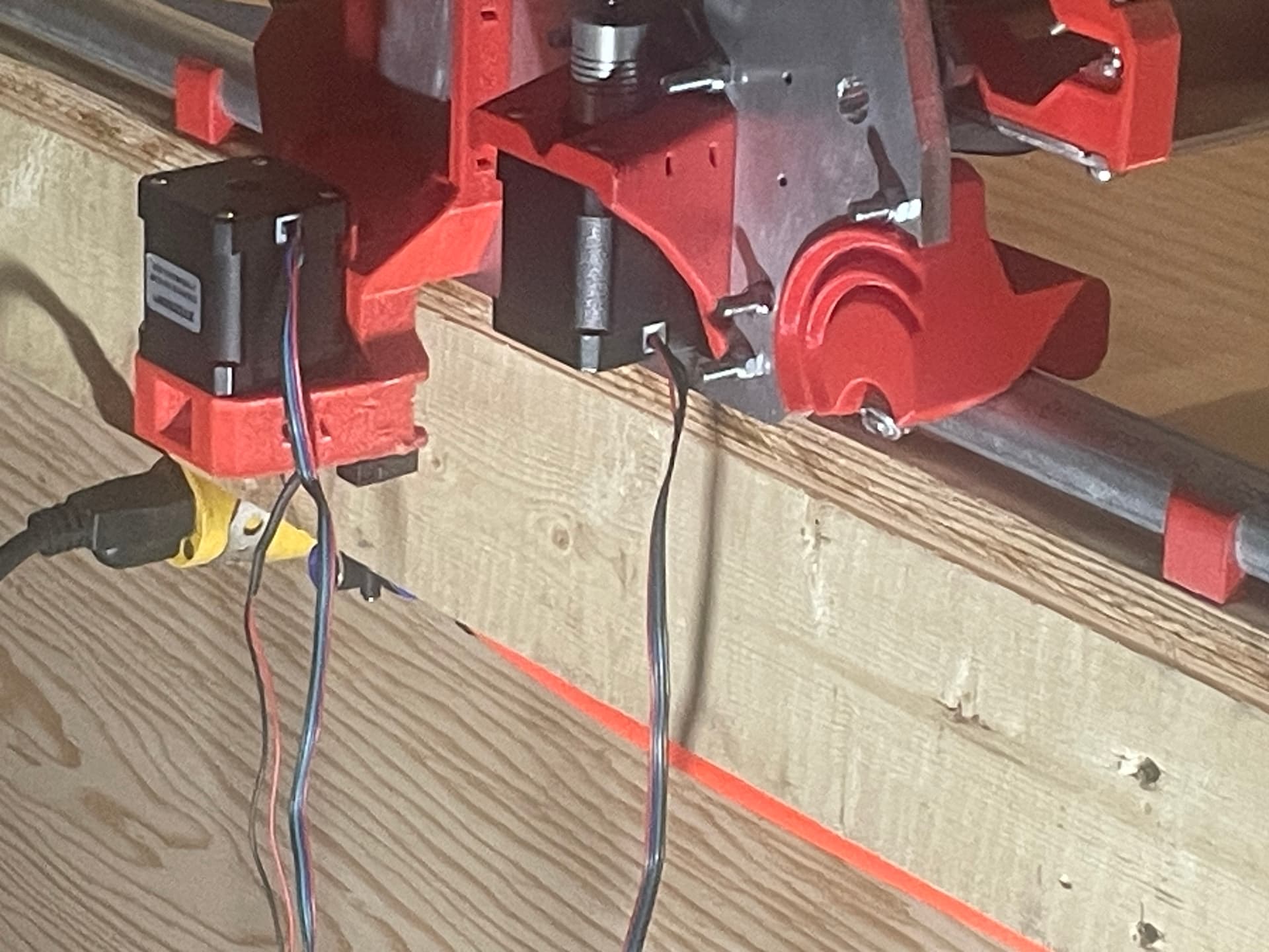
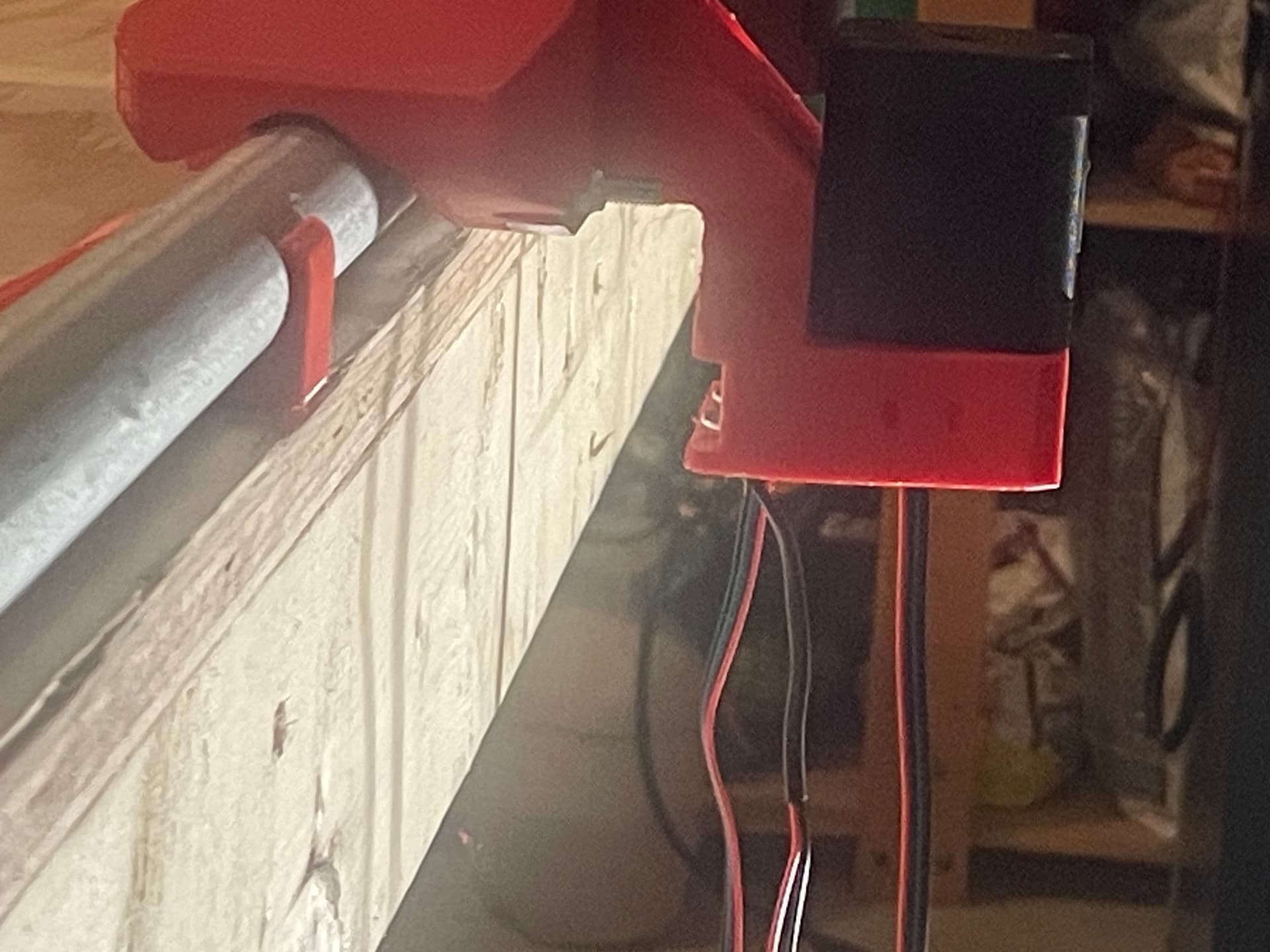
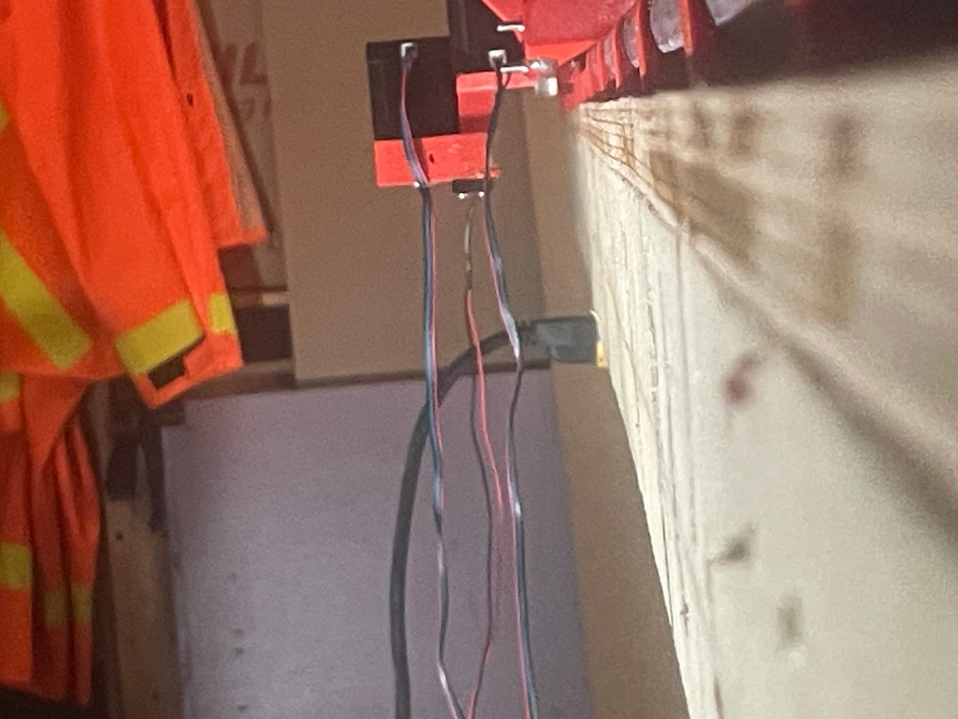
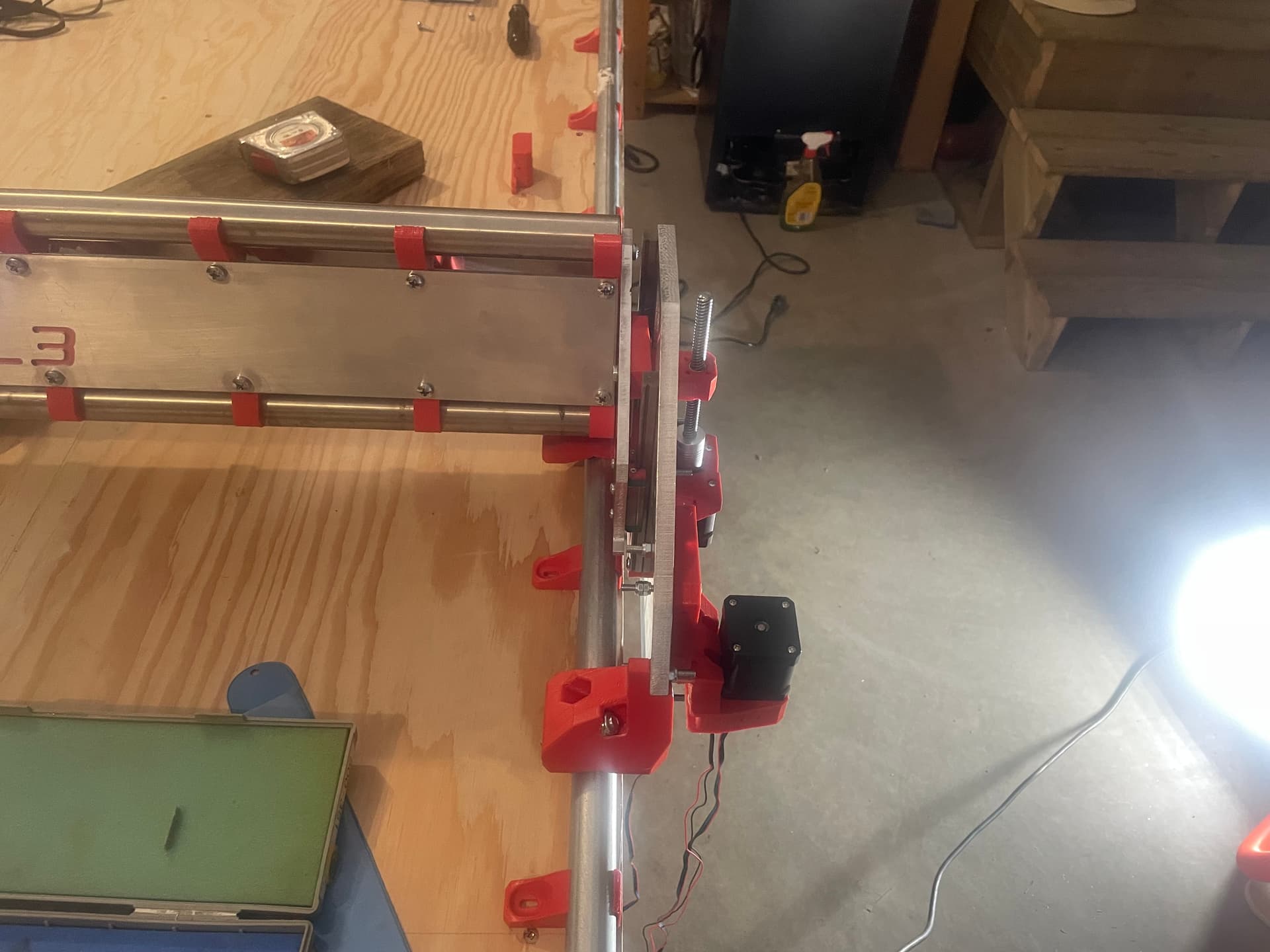
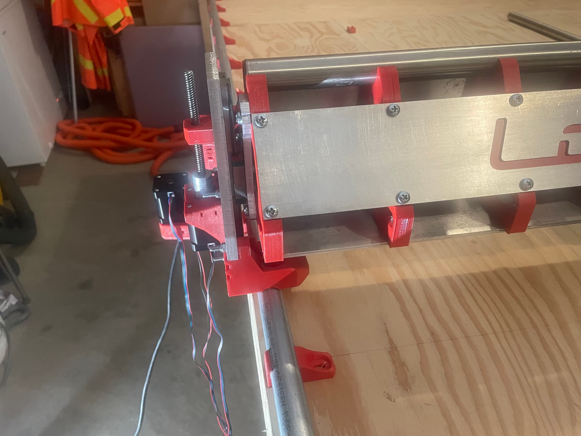
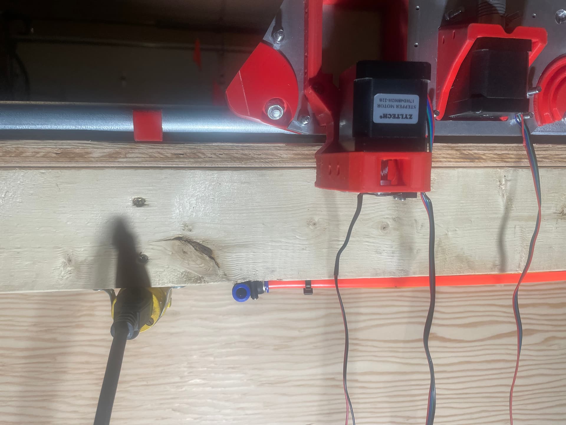
Yes, it’s kind of hard to visualize if you aren’t standing in front of it. Hopefully these pics will help…
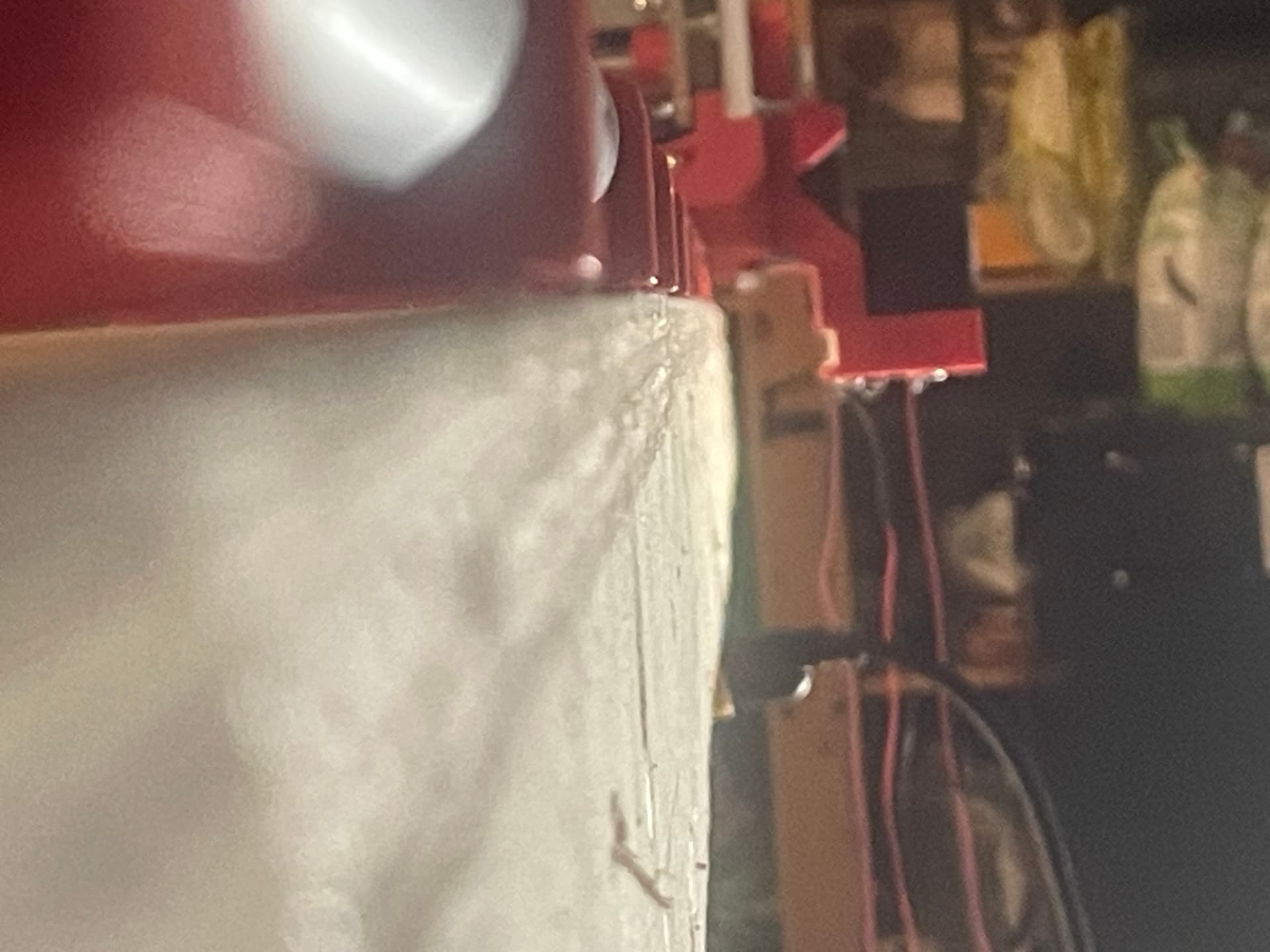
If this is something trivial for you, then please and thank you. If it turns into a PITA, then please don’t bother yourself. I don’t want to place a big ask on you.
If I understood the process that you used to remix @Fabien 's design, I could probably muddle my way through (although it might end up looking a bit less than elegant). Any tips on where to start? (caveat - explain it like I’m clueless).
So looking at your pics, yeah yours is definitely going to be doing something different than ours, your table really does end right at the conduit, ours we have some lip still, well a significant amount compared to yours. Your motor can quite literally sit flush against the YZ plate.
For you, I’d probably start slicing and dicing. So split the part by the face the stepper would fasten to the body. Then maybe split the top part towards the outside and remove that middle chunk that’s leftover, slide the bottom in until your stepper almost flushes up with the vertical, then fill in the middle. What you might also need to do, is enlargen the area under the stepper too, because I think the stepper might flush out before the idlers get to where you want.
I’m not sure if any of that was followable, I’ll see if I can draw it up a little later for you lol
1 Like
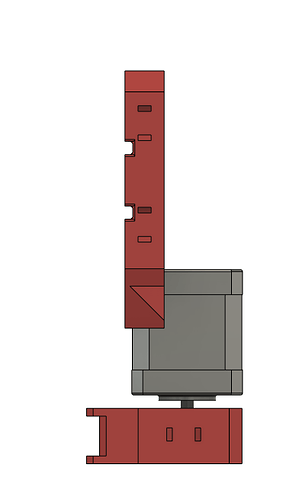
@Bartman so i just quickly opened it up and sliced and moved the bottom in 22mm and you’ll see in this screenshot how the stepper would be “inside” the mounting plate. So Desicions will need to be made, lob out the mounting plate, or move the motor just outside the mounting place and lengthen the distance between the motor spindle and the idlers that first contact the belt?
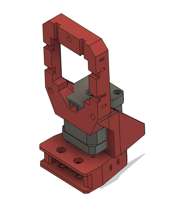
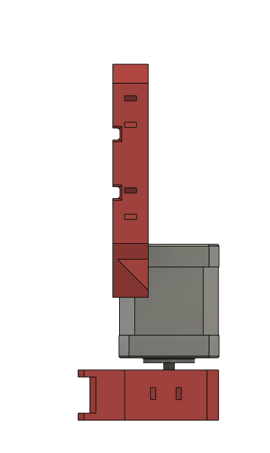
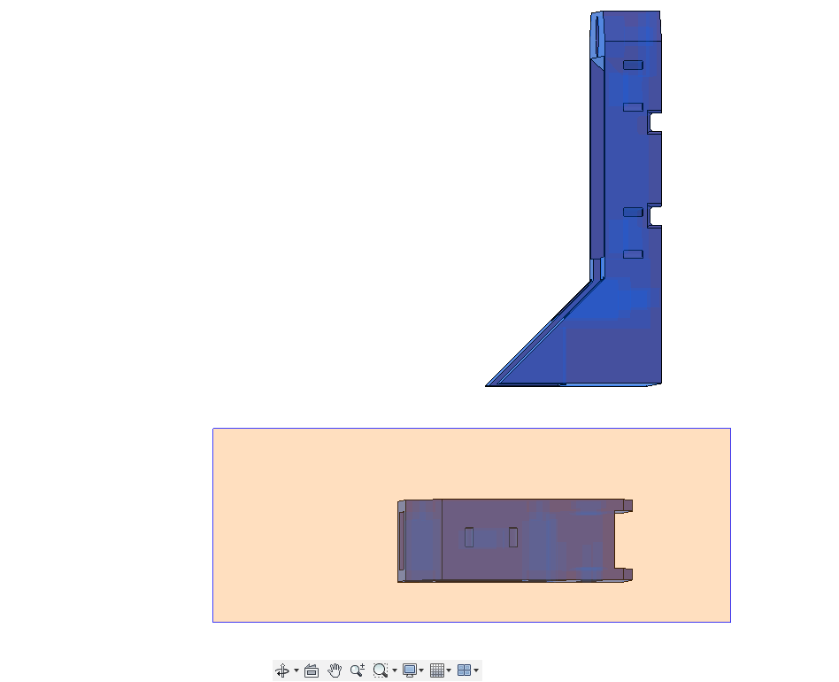
Something like this comes to mind:
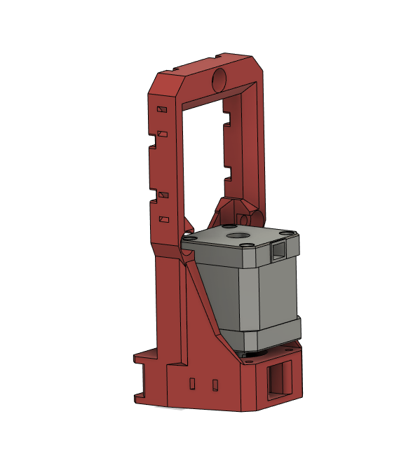
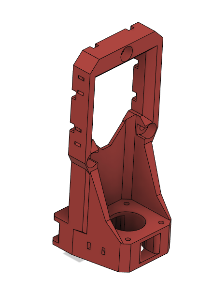
But you may need more reinforcement than this. Might be a few different way’s you’ll want to tweak it and print it and see how stiff it is before changing and doing the same again.
This is all super rough dabbling around, you’ll want to clean it up way more than this lol just thoughts on pape… screen
Well, I am in awe… 9 minutes later you come back with the whole thing pretty much done. I’m sure that in 9 days I might get to the same stage, if I don’t stop to eat or sleep (or go to work…).
Yes, I think that some reinforcement might be needed. Also I noticed that consideration will need to made to accommodate the lower bolt/nut for the rail roller, which sits directly below the left edge of the motor mount
Let me play around in F360 for a bit and see what I can come up with. If I get completely overwhelmed, I’ll cry out for help.
Thanks for everything so far.
Okay, this is me showing my lack of knowledge about F360 and editing/remixing files.
How do I “split” the top part from the bottom part?
I tried deleting some of the parts in the middle, but F360 tells me that I can’t delete individual faces, only the entire body. Other faces I can delete, but I get to a point where it won’t let me delete any more.
Also when I get the top and bottom parts split, it won’t let me select just the bottom part to move, only the entire body.
Is this because I am working from a STEP file, and not from a DFX or F3D file?
And would you prefer to continue this discussion in PM so I don’t derail your entire build thread?
1 Like
I’ll message you!
With help from @Rob_W, I managed to get the rail side motor mount figured out. Many thanks!!!
I’ll return this thread to its regular scheduled programming now. ![]()
1 Like
Eh my next step always seems clear the clutter off the CNC bed so I can start another project. It keeps somehow turning into storage between each piece haha
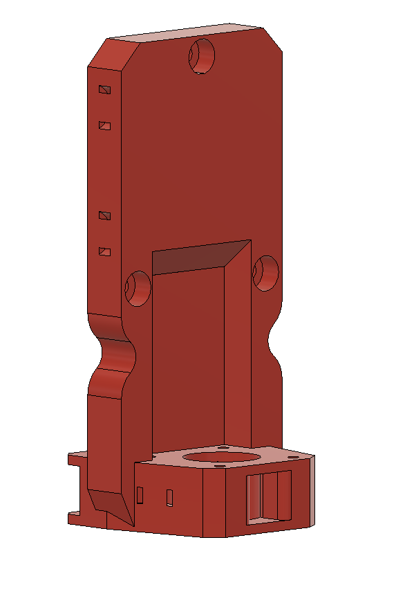
Another way to tackle this would be to let the motor in place, and make the space between the motor and idlers larger…
Probably easier to design it this way, this should be a single sketch édit…
1 Like
Yeah the only downside to that as well, just puts the motor out a little further than it would technically need to be, maybe not an issue
Klipper … klipper … klipper. I think a lot of folks moving from 3d printing to CNC loves this option.
Which post processor do you apply and do you mind sharing the printer.cfg?
I can help you. Start your own thread topic by going to the main forum topic list and click the plus in the lower right or the new topic button upper right (if on a phone).
Edit: my klipper details are here
2 Likes
I’m using GitHub - flyfisher604/mpcnc_post_processor: Marlin/MPCNC posts processor for Fusion 360 for the post processor and noobydp’s klipper cnc macros GitHub - noobydp/CNC-Macros: CNC Macros for Klipper
3 Likes