Yup, my belt holders are in that github link above. I haven’t changed anything with them, they are exactly what’s on my lowrider. I haven’t gotten around to documenting anything about it though but I think they are self explanatory.
I hope to be back at it in the next week or so as I have a few things I need to run through the lowrider, I’ll try to add some more pics and documentation.
Yup klipper has been great for me, I’m not really feeling like I’m hacking away to get things working. The initial setup was just a bit of trail and error to figure out what was needed, but I did that already so I can share with others. I’m basically using vanilla klipper with a macros packaged that takes care of some common commands and workspace setting, as well as a postprocessor for fusion360. If you plan to use fusion360 cam and klipper, that’s what ive been doing without issue. The gentleman that built out the macros package has been working on a lot of new things too like multidirectional probing and tool change z offsetting macros as well, I chat with him a lot on Discord and he’s having a blast coming up with new macros.
But in short, I like it a lot. I can’t see myself going back to marlin or grbl. I did just order a kit for the milo 1.5 so I’m excited to see how reprap firmware is as that seems to be preferred for that project, but klipper on my lowrider has been fun.
Won’t be able to use jackpot, I’m using a btt manta mp5 with cb1 on my lowrider.
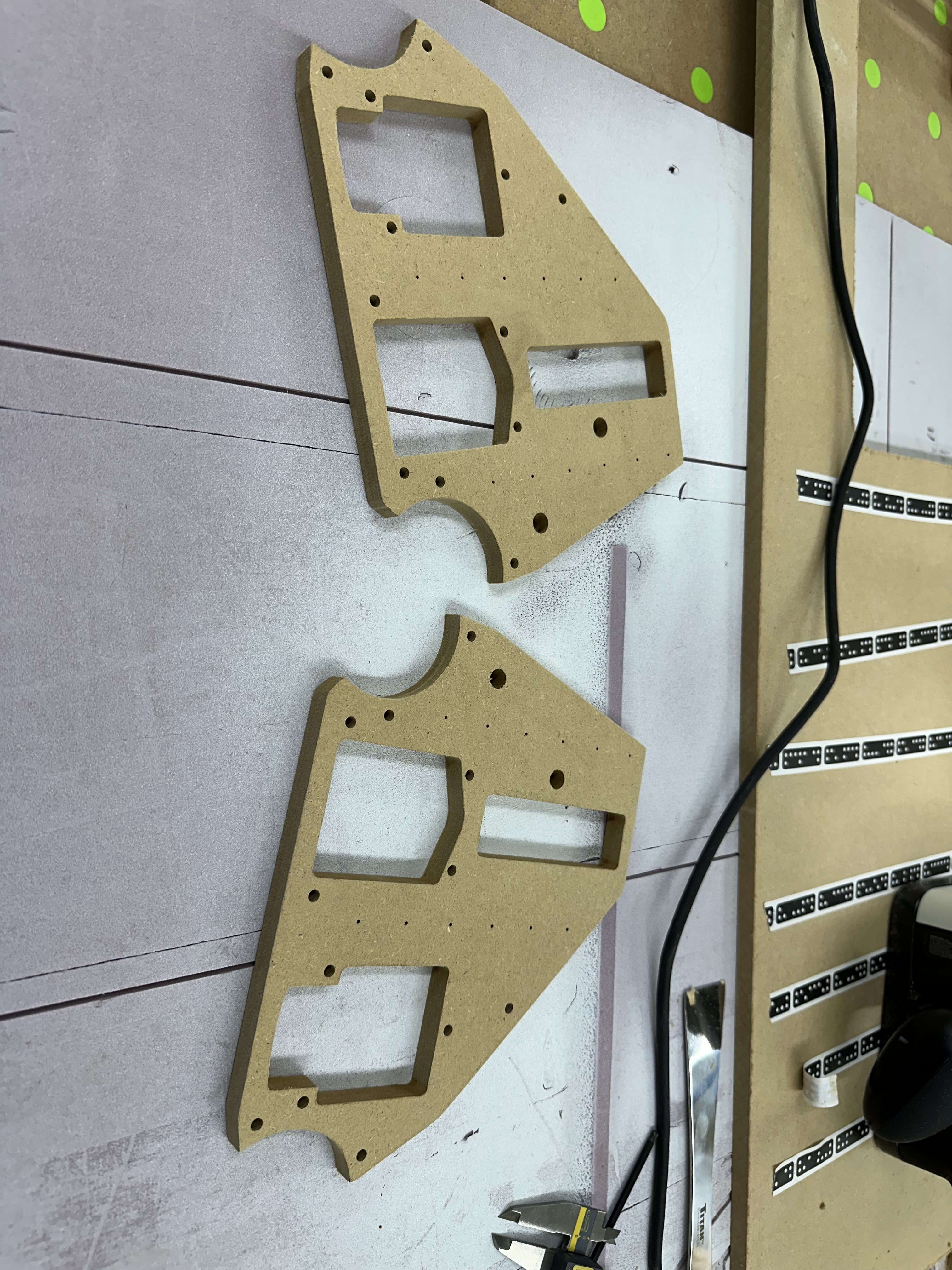
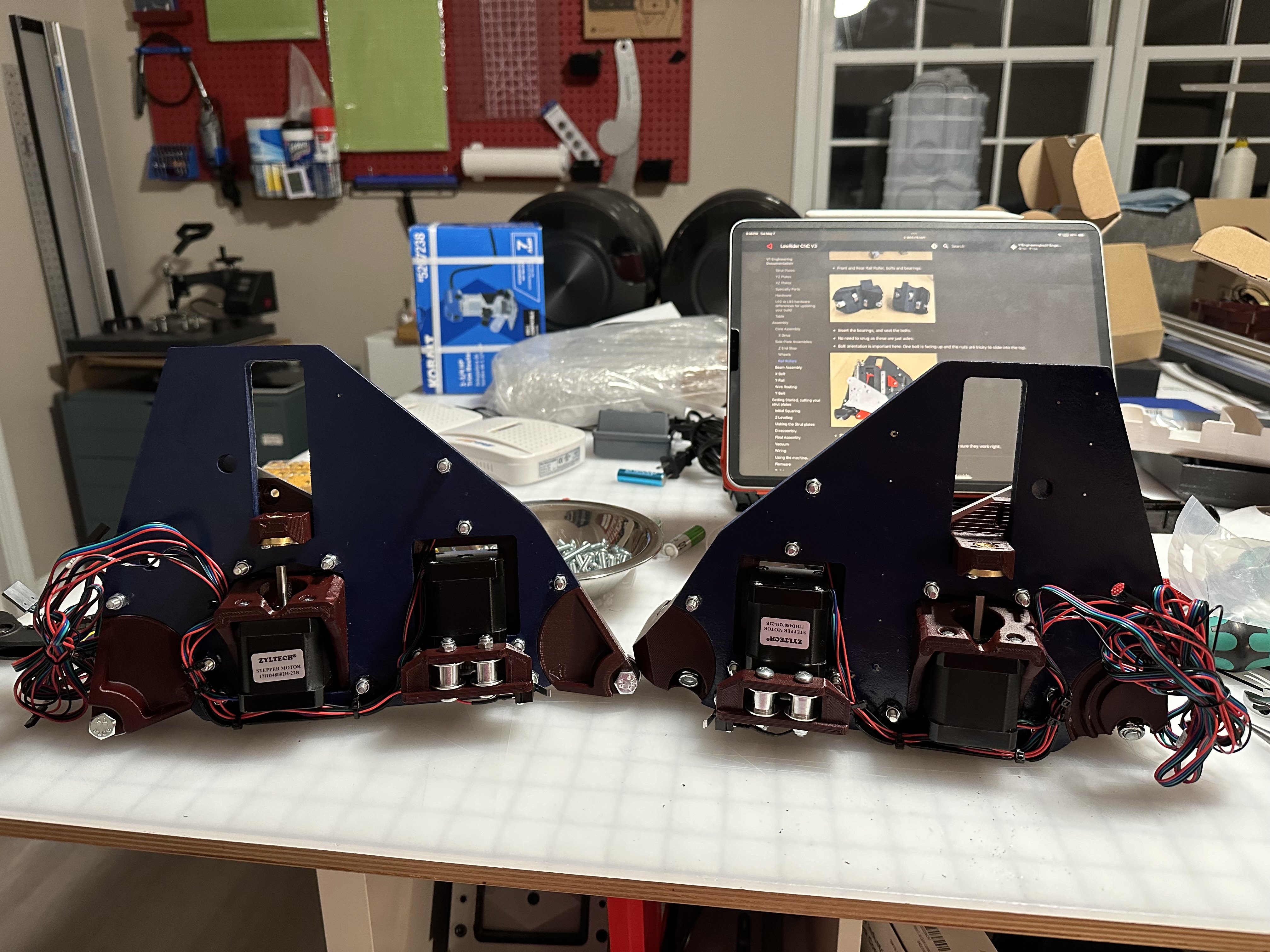
Since I have a Shaper Origin, saved a bit of money and cut these myself. Going to do the cutouts for the braces with it as well and then cut them to length on the table saw or with my track saw. I just really don’t want to build it and then take it apart after cutting the braces.
Nice! I’ve always wanted one of them, just couldn’t use it enough to justify it.
I don’t recall having to take anything apart to add the braces, but what I wish I did was print the strut designs that have the trapped nut or super glued the nuts in place. It’s absolutely miserable trying to hold a wrench in between the braces while trying to fasten all the bolts that secure them.
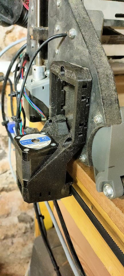
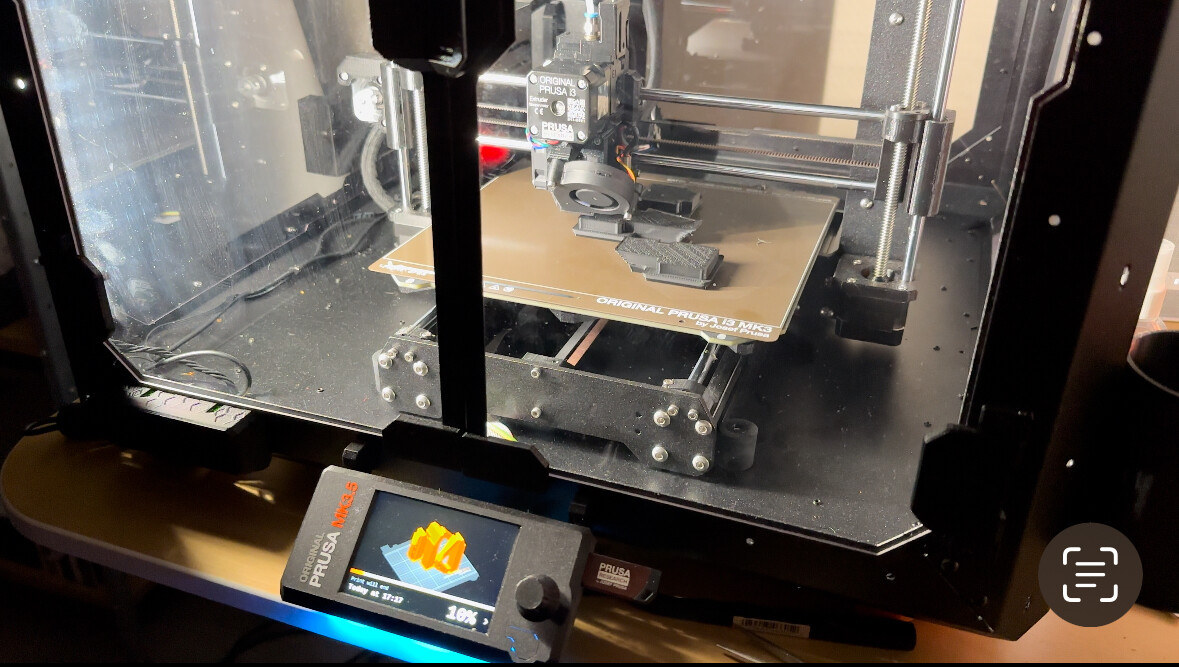
I finally got around printeng and installing those…
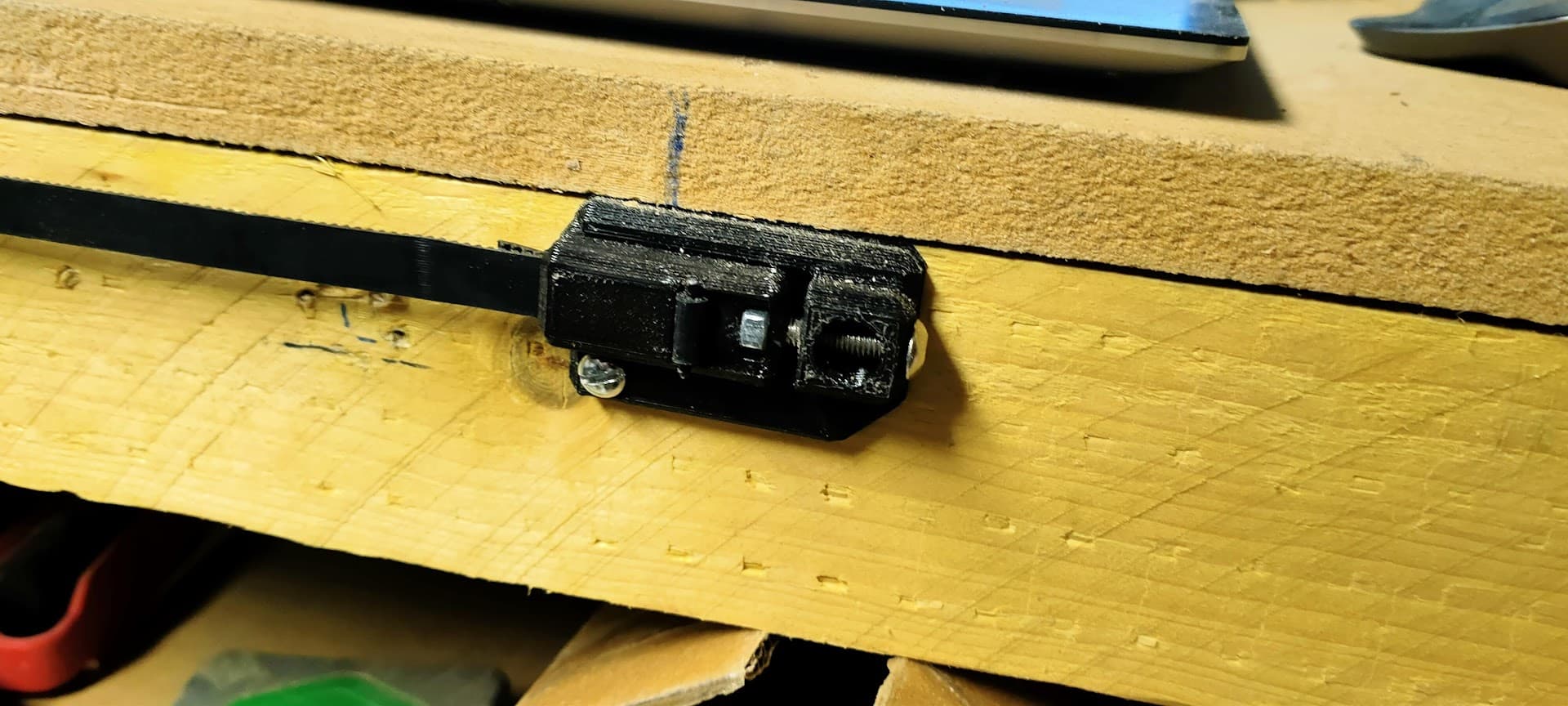
I needed to mirror them for my setup, and had to re-rpint with a slighly larger path for the belt as it was a bit too snug (thanks for the step file!)
Might be my printer, but I think a .3mm increase would do nicely …
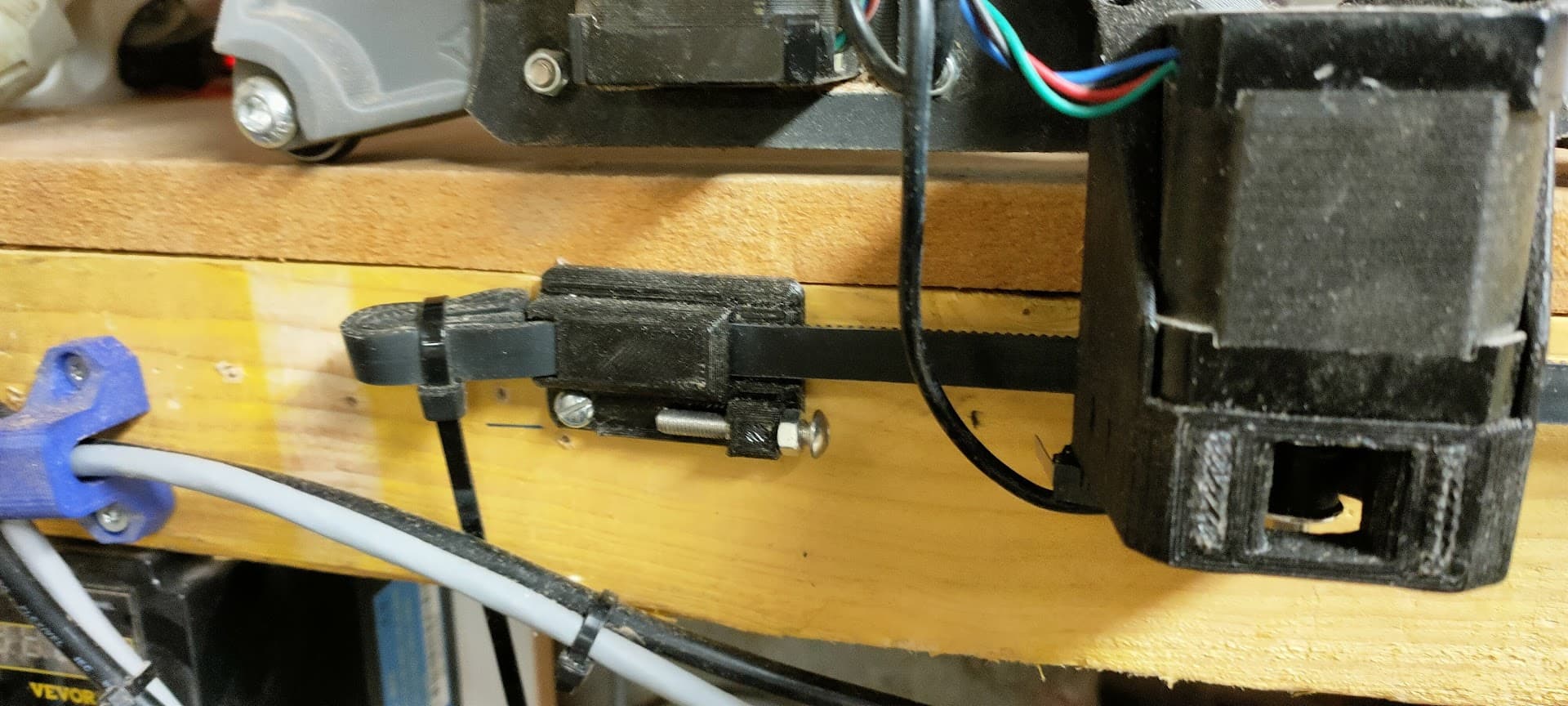
Also, I didn’t understand how I was supposed to attach the small endstop slider, but I replaced it with an M5 screw anyway, as I prefer this method of adjusting the endstop
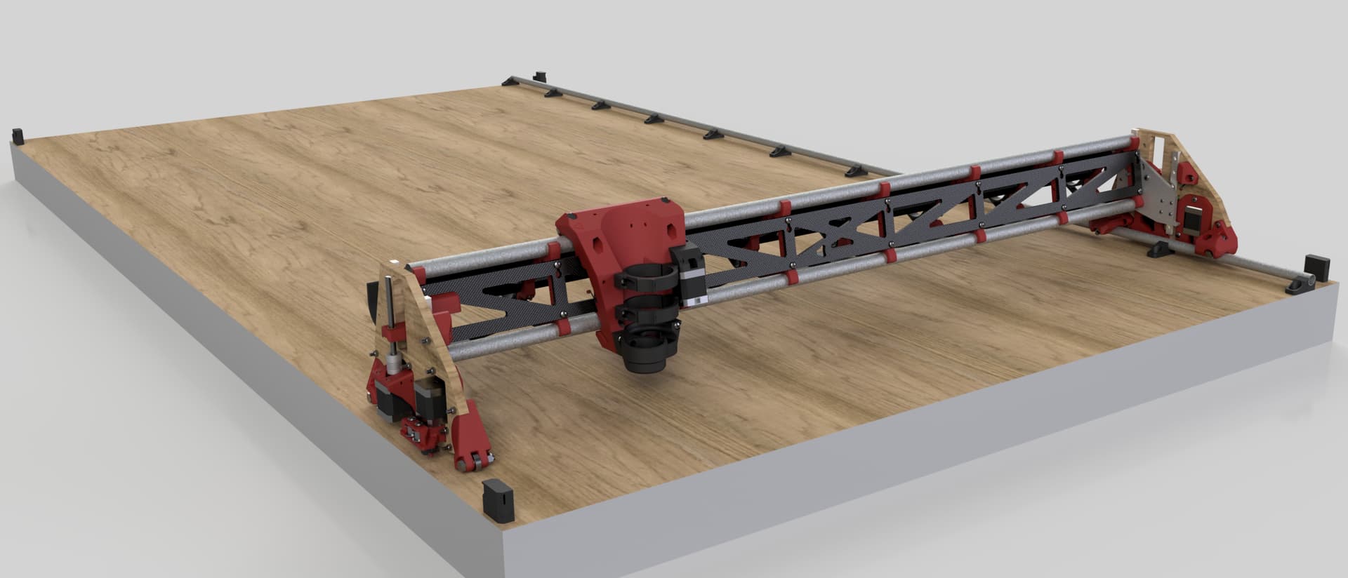
@DougJoseph : I am getting ready to print the strut table extenders and I am somewhat confused about the description talking about your nonstandard layout. If I print these as they are, and am planning on using them for a standard layout build, will they work? Without seeing it all built yet in front of me I am having a hard time visualizing what is front and what is back and what is left and what is right!
My understanding is that “front” would be the short edge of the table with the router facing you so you can change bits, etc, and rear would be about 8ft away from me with the router also facing me. Is that a correct assessment? That would then indicate what is right and what is left.
If I am looking at hole spacing, the front / rear don’t add up, so would I want to mirror all of the extensions, or is my understanding of front / rear incorrect and they are fine?
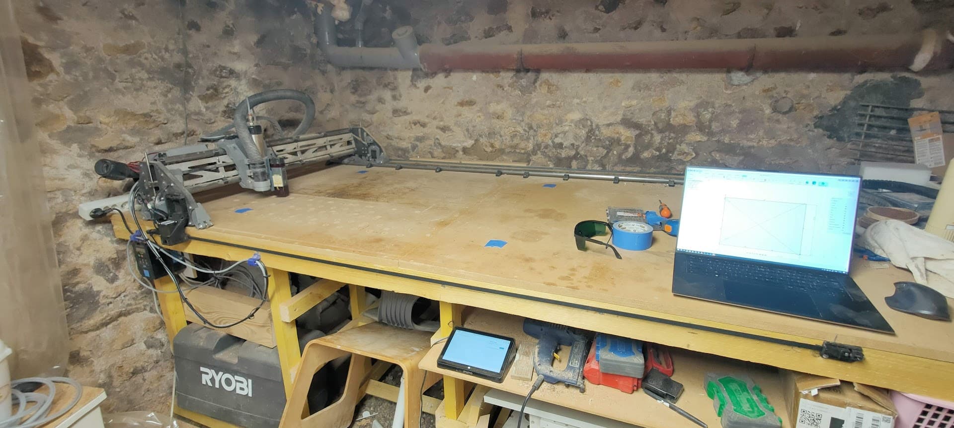
In the below picture, is the closest corner normally considered “Front-Left?”
OK, so the thing about my table is when facing front, my Y rail is on the left side. On a stock LowRider, the Y rail is on the right side. Those extenders are made to slip into metal strut (aka “unistrut” or “superstrut”) so assuming you are doing metal strut like that, the printed extender parts need mirrored in your slicer if you have a stock LowRider, or not if you have your LowRider non-stock like I do.
The only difference between the 1.0 and 1.1 is the latter has 10mm worth of adjustability on the location of the belt-tensioner+endstop mounts on one side (the non-rail side).
Sweet, looks good! Yup I left them pretty tight for the belt… definitely too tight cause I fought mine as well, I’ll push it open a bit more and reupload for the future.
For the endstop slide, it was suppose to accept an M3 heat set and then the endstop slide would be adjusted and secured down with an m3 going through the slot on the endstop slide into the plate where the heatset is to secure it. I went that route when talking to people (i think in this thread) about how the divots by using a screw head could cause some unreliable homings.
But glad you like it! It came out really well, not something I’m used to on first try haha so let me know if you find any other issues with it.
I think the only other issue I had was the endstop switch mounting, apparently there are two different sizes and I modeled for the one I don’t have of course so I just self tapped a new hole for mine
Man, these screws are hard to get to when you got fat fingers! Got it all done though with the cable trays (which I would suggest you not add until wheels and everything are done! Getting around them was a pain!!