Hey guys I have been running the Dewalt 660 on my Primo but I think I would really like to have RPM control and a bit more power so I was looking at 65mm spindles.
Thoughts on water cooled vs air cooled spindle?
I do this as a hobby and water seams to add some complexity with the pump and water and my rig is in a unheated garage.
Is water that much better than air cooled or other things I should consider?
i run 1.5kw air cooled spindles on both my Primo and LR3. I didn’t want to deal with water lines and all that. So far i haven’t had any issues with heat on the mounts for either. My LR3 mount is printed from ASA though. Im about to print a new mount for the LR3 that will have a lot more coverage on the spindle but i don’t expect to have any heat issues still.
Thank you for the insights on your setup.
I had thought about doing the same, printing the mount out of ASA or ABS.
Yeah I have to agree the extra complexity of the water lines for my hobby machine I think is more than I want to deal with.
Any other advise when considering a VFD spindle that I may not have thought about?
I dont have a ton of run time on either one yet. The one i got for my Primo was purchased from VEVOR. They were out of stock when i was ready to get one for my LR3 so i went with one off of ebay. I have no idea which is better. Main thing im learning is while the VFD comes with a manual its very broken english. I have had to ask several questions and do tons of googling to find out what settings need to be changed in the VFD and what not. I have a post now trying to get RPM where i can see it.
Also on my LR3 build thread there are the links to each of the spindles i have…
Hopefully that info helps you some. And if you follow along you can learn as i do LOL
2 Likes
Thank you very much I will follow along for sure.
1 Like
Okay so after some back and forth I think I want to say with a 110v Spindle kit to keep wiring in my garage easier. I know it’s not a lot of work to add 220v but everything else I have is 110v so that makes the most sense to my setup. With that said I am looking at this kit:
RATTMMOTOR 0.8KW 110V Spindle Motor Kit, 800W Water Cooled 65mm CNC Router Spindle Motor 110V 400HZ+1.5KW VFD 110V Single to 3 Phase Inverter+65mm Mount Clamp+ER11 Collet+80W Water Pump for CNC Router https://a.co/d/9PHW0h1
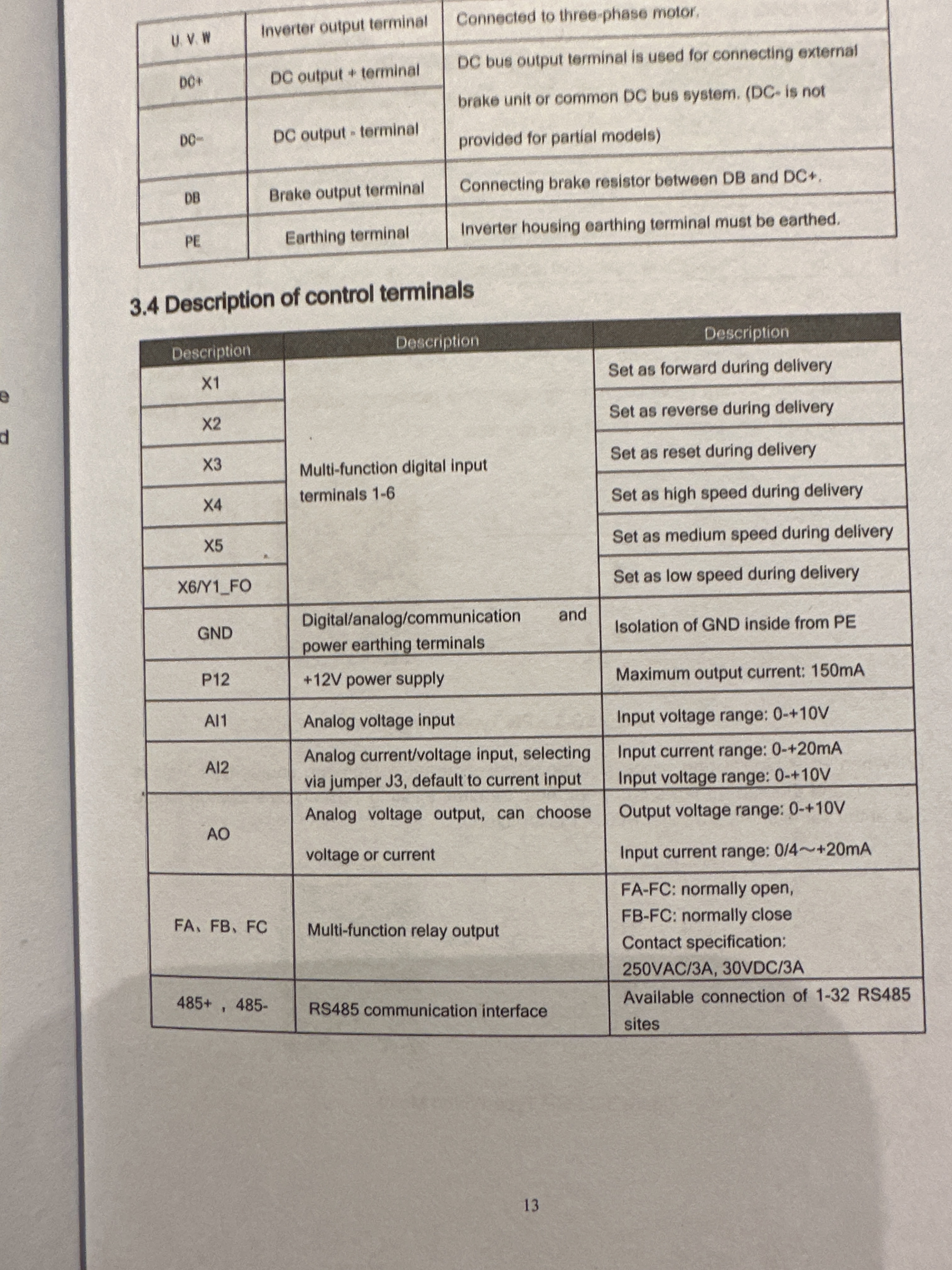
I confirmed the controller has RS-485 interface.
Is there anything else I need to consider?
Also that kit has the plugs but needs wiring to connect the Spindle and VFD , any recommendations on wiring to use?
Then of course, how to hook that up for spindle direction and speed control in the CNC program. I’ve done manual and CNC machining, and having the G&M code tell the spindle to run at different speeds for hogging and finish passes, ramp up and down at sharp corners etc. is invaluable. Are you handling that? Thoughts from folks on best way, which controller etc?
That is my next bridge to cross for sure, if anyone has some good guide or links I would be happy to have them.
My MPCNC is controlled via a Duet 3 board so its a little different than Marlin.
I know there are the PWM to Analog signal converters so I am not sure if I need one of those or not just yet.
It looks like the Rattm 800w air and water cooled units all use PWM input.
Anyone know what or how I might connect this to a Duet 3 board based for On/Off and Speed control?
There are a number of topics on this forum discussing connecting a VFD to a control board. While the fragment of the manual you publish does not say explicitly, based on other topics, your VFD is expecting an input of 0V to 10V on the “Analog Voltage Input,” which will be mapped to the min and max RPM of your spindle.
To get PWM of a control board to set the RPM of the VFD there are two pieces of work:
- Setup the firmware to take RPM commands (either M3 or inline), and map those to specific PWM values on a PWM enabled pin on your control board.
- Conver the 3.3V or 5V PWM signal generated by the control board to a 10V signal expected by the VFD.
You don’t say what firmware you are using. I checked the Marlin source, and could not find a board definition for any of the Duet boards, nor a pins file for a Duet board. Assuming Marlin, you are going to need to have the following two defines in your firmware build:
#define SPINDLE_LASER_ENA_PIN PB0
#define SPINDLE_LASER_PWM_PIN PC9
The PB0 and PC9 are pins for the SKR pro board. You will need pins specific to your Duet board…and the PWM pin needs to support PWM.
Once the pin is defined, there are settings in configuration_adv.h for turning on spindle support and for mapping the RPM settings in the g-code to PWM values.
As for converting the signal to 10V, I’ve seen a couple of circuit diagrams mentioned in a couple of topics on connecting control boards to VFDs. And there are references to a conversion board. A quick search yields this board for converting from 5V to 10V (not sure if the Duet is 3.3V or a 5.0V board.
Thank you for the detailed post Robert I really appreciate it and yes I should have provided more details.
So I am using a Fystec Big Dipper RepRap board:
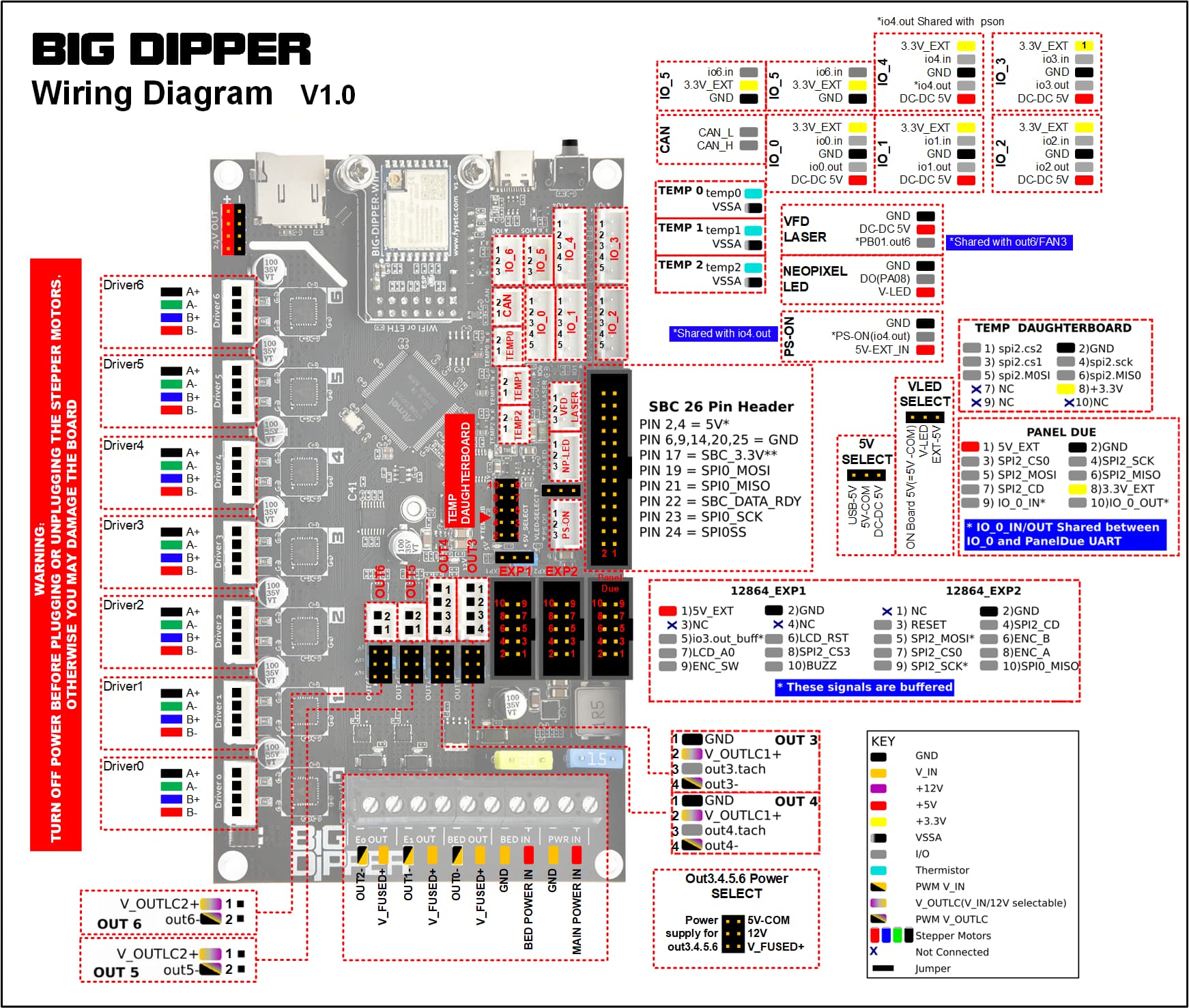
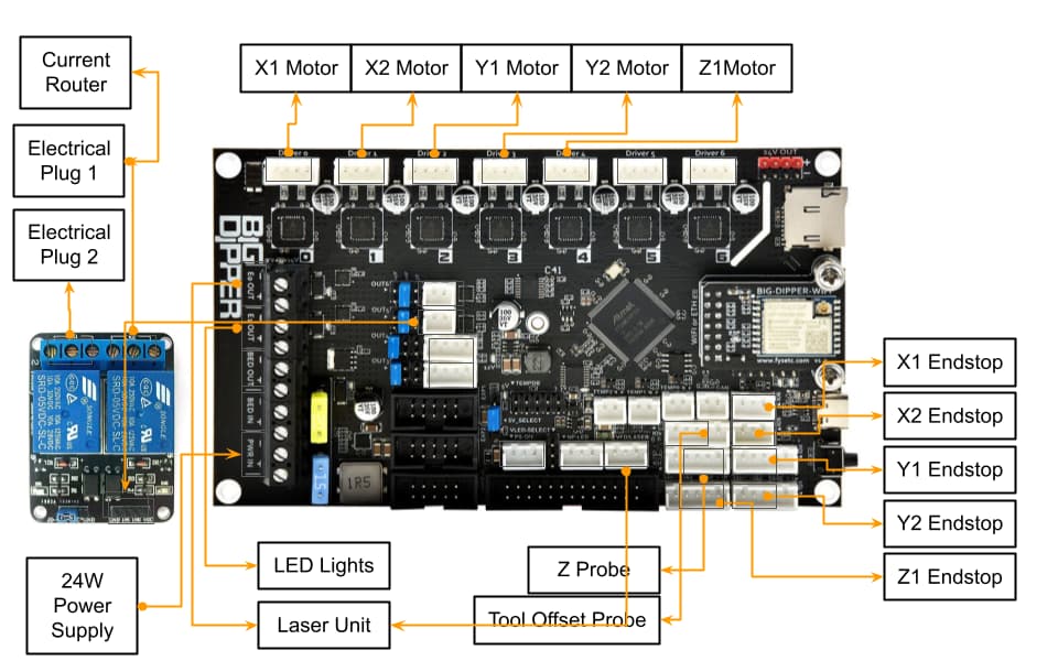
Here is how my board is setup now:
So my plan is to use the Out3 header on the board for PWM signal but as was pointed out I will need to convert the 5v PWM to a 0-10v Signal for the VFD. Will I then need a second pin like Out4 header as well to turn the VFD on and off?
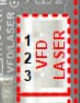
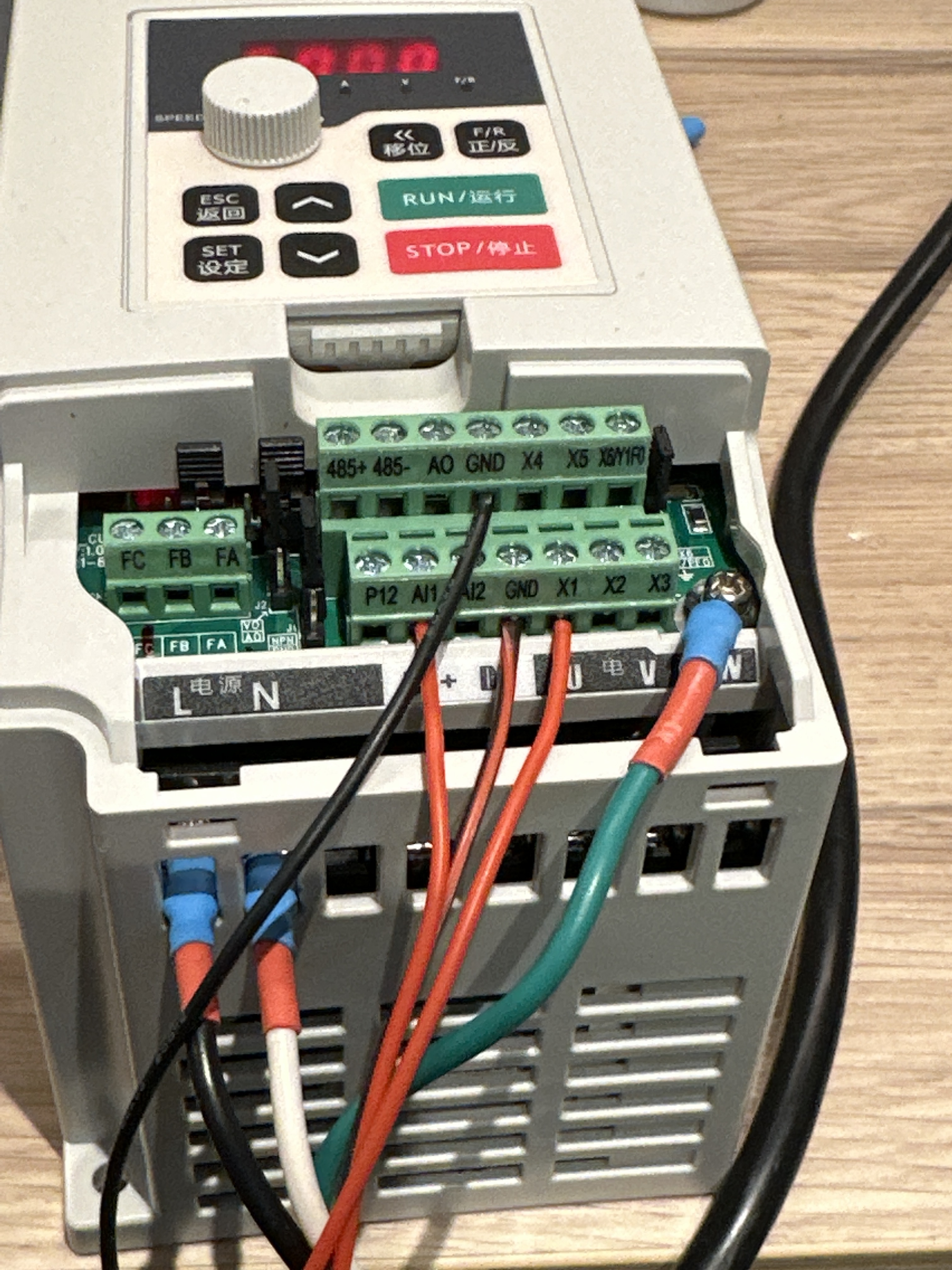
Looking at your images, it appears that PB01.out6 is the default place to drive a VFD:
If you are looking to use a different pin, make sure it is PWM capable.
Will I then need a second pin like Out4 header as well to turn the VFD on and off?
I have no idea about on/off, and I’ve not seen it written about on the forum. I don’t have a VFD. Out of curiosity, I scan the docs for the different ones that come across the forum. I’ve wondered about on/off since typically I don’t see any sort of enable input to these devices. Looking at the snippet of docs you provided, I don’t see an enable there either. If it was important, you could use the enable pin to drive a relay that powered your VFD.
I assume you’re running RepRap firmware on this board?
So I currently have a 12 volt laser using the Out6 Laser VFD pin and its working well so I didnt want to undo that if I need to buy a PWM converter board anyway.
So I was planning to use Out3 or Out4 pin 4 at with the jumper on 5volt to output the 0-5v pwm signal.
Yes you are right, currently I have a relay setup that is triggered using Out5 to turn the relay for my router on and off, I guess I could just unplug the router and plug the VFD into that plug and use that to turn the VFD on and off.
Yes I am running RepRap firmware on the board.
Based on some articles on the Duet website I just ordered this converter:
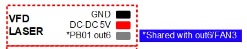
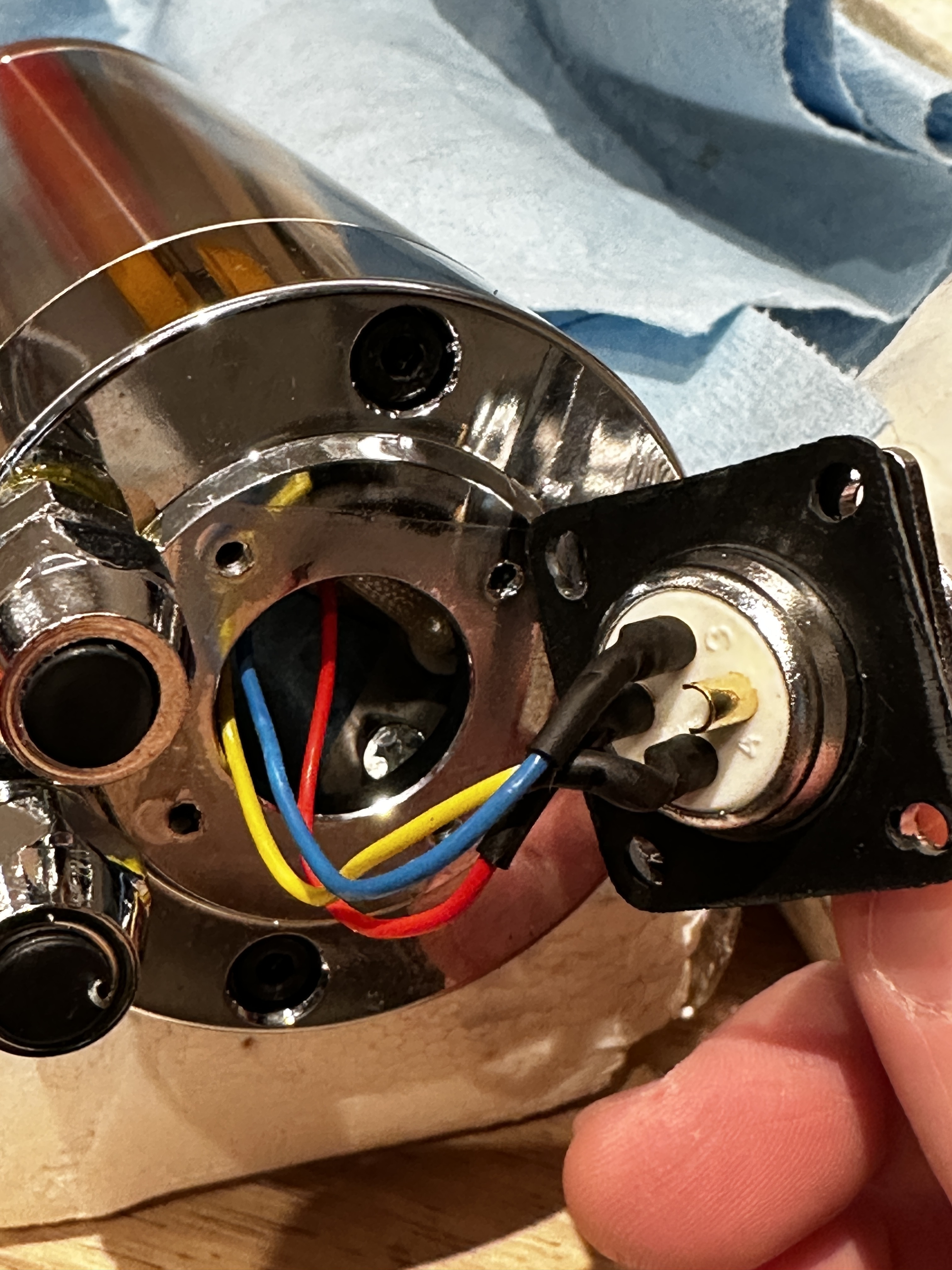
Also I found my spindle was t grounded so I setup an internal ground for it as well while I wait for more parts to arrive.
Okay so I had a chance to made some progress today.
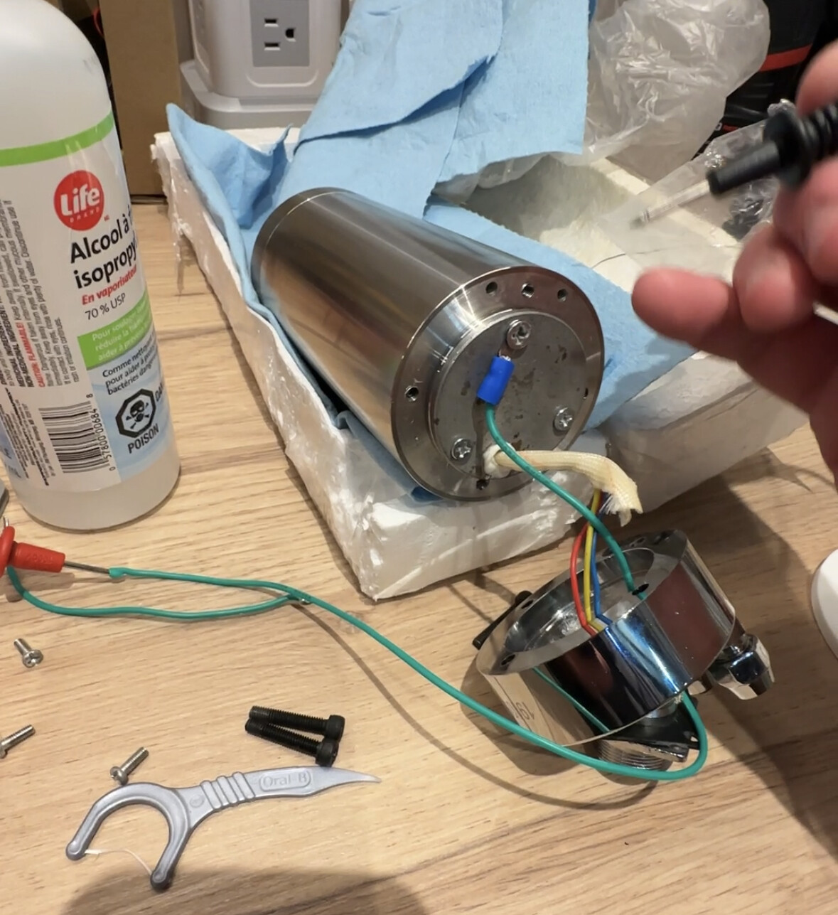
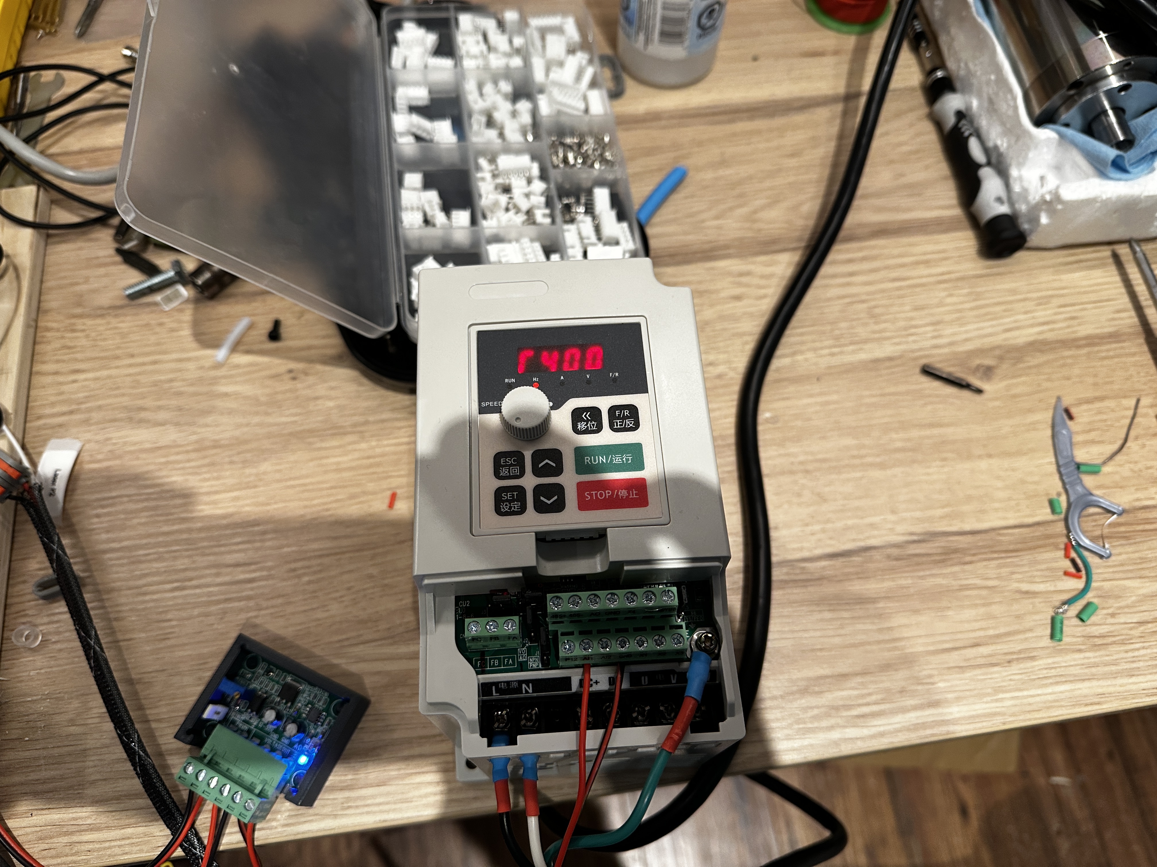
I got the PWM to Voltage converter in and wired up. I created my spindle in the Config and I can see the screen change on the VFD as I turn the spindle on and off in software and it will go from 0 to 400 hrz on the VFD display but it won’t trigger the run.
I setup a second output to connect to X1 on the VFD to send the forward command but it didn’t seam to do anything on the VFD.
Any help or thoughts would be great
Lead screw for Z access upgrade.
Hey guys on my MPCNc with the spindle the Z axis falls when the steppers are disabled.
If I change out the lead screw can I prevent this and what would a recommend change be?
A falling Z is a common problem for Lowriders, but not usually for a Primos. Assuming you built your machine using the V1 specified parts, you have a 4-start lead screw. They make 2-start and 1-start lead screws. A 2-start lead screw moves 1/2 the amount per turn compared to a 4-start, and 1-start moves 1/4 the amount. Changing to a 2-start or 1-start lead screw will impact the max Z federate of your machine.
Personally, I would start with a 2-start lead screw. Unfortunately, they are not common. The 2-start lead screws move 4mm per turn, so they are sometimes labeled as T8-4. Here is one source. You will also need a matching T8*4 nut.
After installing a 2-start lead screw, you will need to cut the steps per mm for the Z axis by half. This can be done by the M92 g-code or, sometimes from the display.
1 Like