Spindle RPM

I am running a 1.5kw air cooled Spindle on my Primo (and also on my LR3) I’m looking to see if its possible to tie RPM and On/Off control into Marlin on my SKR Pro 1.2. Or if i can hook up an additional small LCD screen that will display the RPM. My VFD doesnt give this information but from my understanding it will output it…but its all Chinese to me…

Link to VFD…

VFD Manual…

I have tried googling but i just cant come up with the right question to ask or what to search for to get me to anything i understand. Not many people outside of V1 running VFD spindles with Marlin firmware lol.

Also ill throw this in here too…the VFD i got for my LR3 is a little different than the one on my Primo…

VFD…
https://www.amazon.com/Variable-Frequency-Inverter-Converter-HUANYANG/dp/B0775QGLVJ/ref=asc_df_B0775F4G47/?tag=hyprod-20&linkCode=df0&hvadid=309807921328&hvpos=&hvnetw=g&hvrand=11016759471488520013&hvpone=&hvptwo=&hvqmt=&hvdev=c&hvdvcmdl=&hvlocint=&hvlocphy=9011671&hvtargid=pla-570008466211&th=1
VFD Manual…

Thanks in advance for any and all assistance!!!

1 Like

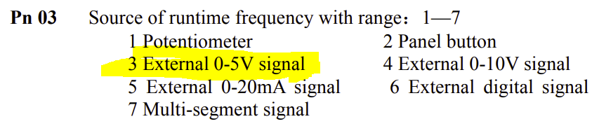
I have no practical knowledge of VFDs. I’ve never owned one. But, every time a VFD question comes across the forum, I’ve spent a bit of time in research. I find them an interesting puzzle.

Read from VFD

… LCD screen that will display the RPM. My VFD doesnt give this information …

Are you sure? According to the manual you reference, display/adjustment item Pn 01 goes from 1 to 30,000. That sounds like an RPM setting.

image

If you are setting the frequency on the VFD and just need to map those values to RPM, then you can use a tachometer like this one. That is what I did with the routers I’ve used on my Burly and Primo. I then printed up a table I keep with my machine. I also suspect that the specification of your spindle can be used to map the output frequency to RPM.

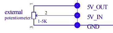
Dial it in with a potentiometer
The next solution up in terms of simplicity is to add a 1K to 5K potentiometer. A tachometer will allow you to label the print dial markings mapping rotation of the pot to RPM. Hookup from the manual:

image

Set the RPM from the SKR Pro board
If you want to connect your VFD to your MPCNC you will be using the PWM output from the SKR Pro board. You are fortunate since this VFD has a 5V input. Most I’ve seen in the past use a 10V input. You will need to play some with the firmware settings to map the PWM values output to the g-code G0/G1 ‘S’ parameter spindle values. A few settings that stand out:

//#define SPINDLE_FEATURE
#define LASER_FEATURE

You probably need to commet out LASER_FEATURE, and uncomment SPINDLE_FEATURE

 /**
   * Speed / Power can be set ('M3 S') and displayed in terms of:
   *  - PWM255  (S0 - S255)
   *  - PERCENT (S0 - S100)
   *  - RPM     (S0 - S50000)  Best for use with a spindle
   *  - SERVO   (S0 - S180)
   */
  #define CUTTER_POWER_UNIT PWM255

You need to set CUTTER_POWER_UNIT to RPM

You will likely also need to adjust M3/M4 Power Equation to match your VFD/Spindle combo.

As for connection, V1 maintained firmware set a PWM pin in the top of the configuration.h file:

#define SPINDLE_LASER_PWM_PIN PC9
#define SPINDLE_LASER_ENA_PIN PB0 // Heater2

You will need to connect pin PC9 on the Skr Pro to the 5V in on the VFD, and you will need to connect the grounds together as well.

External display
The VFD has a pin that shares the frequency. You will need to figure out how that frequency maps to RPM by using a tachometer or other method. You can use that frequency output pin with a microprocessor and display to output the RPM. This is not a hard thing to build, but I’ll not add any details unless this is your selected solution.

2 Likes

Honestly no i am not sure. But if its there i sure cant figure out how to find it. I have been hesitant to start pushing buttons not knowing what I’m looking for. Don’t want to accidentally change something and not know what i changed or how to change it back. Currently it just shows frequency on the screen. 0-400.00

I have thought about this and it is still an option. It just seems there should be a better/nicer way to do it. Im just not smart enough to figure it out LOL.

The VFD on my LR3 has a potentiometer on it already and thats how it is set. But still no true RPM readout that i was hoping for.

Ok this makes some sense. Thank you for this! Now i have a good idea what i need to do to hook it up. Will i need to change any settings in the VFD to allow that 5v in to control the speed? Will i still have manual control from the VFD after? this is the stuff i couldnt understand from the manual.

The nerd in me wants to see the RPM displayed. IDK why it matters but it will bug me if i cant see it lol. Im good with setting up a DIY display. Or is it possible to have it fed back into marlin to display on the screen? Sorta like a Hot Bed Temp would be displayed?

Thank you so much for your help so far!!!

But if its there i sure cant figure out how to find it.

According to the manual, when the spindle is not running, you press the SET button and then the up and down arrow keys. You are looking for the 01 menu item. Note that even if this works, I’m not sure it will display dynamic values as set by your potentiometer.

It just seems there should be a better/nicer way

As added in an edit to my post, I suspect that if you know what you are looking for, something in the spindle spec will tell you the mapping between frequency and RPM.

Will i need to change any settings in the VFD to allow that 5v in to control the speed?

Maybe. Assuming your current potentiometer is using the 5V-in for control (there is a 10V in as well), I suspect the PWM signal will work just fine if you remove the pot and use the 5V-in for the PWM. But there are a variety of settings for the 5V-in pin. If you have issues, I would start by setting it this way:

That is menu 03 gets set to 3.

The nerd in me wants to see the RPM displayed.

If you want to create an external display, I can provide more information. You still need to figure out a maping between frequency and RPM to make it work.

1 Like

I believe im making this more confusing trying to figure this out for 2 similar but different VFDs in the same post. The VEVOR VFD does not have a potentiometer on it. that one i have to adjust frequency with the up/down arrows. When i get back home i will look at the menu and see if i can get it to display the RPMs. If thats all it is then that makes this much easier.

Here is the info on the Spindle mounted in my Primo…

Manual…Get ready for a laugh…
http://qiniu.vevor.net/20200514144134221.pdf

I have that Tach you linked in my amazon cart now and will be ordering. So if i cant find mapping for it online i will have that when i get back in town and can manually map it. If you dont mind i would appreciate the info on an external display so i am ready if i need to go that route. I have several ESP8266 and ESP32 boards at home already if those can be used. Will just have to pick up a small display that will work.

Assuming the sales page is accurate, here is the mapping from that page:

Frequency: 200-400 Hz; Speed: 12000-24000 R/min;

So, your RPM is Frequency * 60.

Makes sense to me. I will verify when i get home with the hand held tach to be sure

I’ve never developed a project using an ESP32. I build most of my things using Arduino Nanos or Arduino MicroPros. If I were doing this project, I’d use an Arduino Nano and an LCD 1602A I2C display. This display is big enough to read easily from a distance, can be backlit, and, since it is I2C, simple to wire.

As for calculating the frequency, I’d use PulseIn() to measure the pulse time, and divide to get the frequency. If the pulse width varies, I’d do a running average to smooth the reading out. I’d also use the “timeout” parameter in PulseIn(), since I expect no signal is generated when the VFD is not driving the spindle or when the VFD is turned off.

Power for the Arduino and display is a bit of an issue. I would have loved to power it directly from the VFD, but its 5V and 12V out pins don’t generate enough current for the Arduino and the display. The SKR Pro pins do generate enough current, so you could power it from the SKR Pro, or you could go with another wall wart.

If you decide to go down this road (with an Arduino board), and you need it, I’d be glad to rough out some code.

If it’s not possible to see the current RPM on the Marlin screen or on the VFD then most likely i will be going down this path for both machines. Its a good chance i will go down this path for at least the LR3 because of where i plan to mount the VFD isn’t in direct line of sight. I will get the Nano and Screen ordered. If you don’t mind helping with the code that would be amazing. Im still an extreme noob with the code side… only experience so far is in ESPHome with some small simple sensors i made to work with home assistant.

1 Like

Any real difference between these 2 other than quantity? Looks like one is name brand where the other is aftermarket. Wasnt sure if that was a big deal with these boards. Ive had good luck with the aftermarket nodemcu 8266/ESP32 stuff but wanted to be sure first.

https://smile.amazon.com/ELEGOO-Arduino-ATmega328P-Without-Compatible/dp/B0713XK923/ref=sr_1_2_sspa?crid=2E31ZG6BHDSPO&keywords=arduino%2Bnano&qid=1673229787&sprefix=Ardu%2Caps%2C560&sr=8-2-spons&spLa=ZW5jcnlwdGVkUXVhbGlmaWVyPUFMWjZZR1dEWk1NMFgmZW5jcnlwdGVkSWQ9QTAzNDU1NzUzUFBPMjhPTkxITlhFJmVuY3J5cHRlZEFkSWQ9QTA2NjkyODkxN1hJSjdRU1JQNlpVJndpZGdldE5hbWU9c3BfYXRmJmFjdGlvbj1jbGlja1JlZGlyZWN0JmRvTm90TG9nQ2xpY2s9dHJ1ZQ&th=1

https://smile.amazon.com/Arduino-A000005-ARDUINO-Nano/dp/B0097AU5OU/ref=sr_1_3?crid=2E31ZG6BHDSPO&keywords=arduino+nano&qid=1673229787&sprefix=Ardu%2Caps%2C560&sr=8-3

And i believe this is the screen you suggested…or close to it lol

https://smile.amazon.com/GeeekPi-Character-Backlight-Raspberry-Electrical/dp/B07S7PJYM6/ref=sr_1_4?crid=37B0NNKPA2ELS&keywords=LCD+1602A+I2C&qid=1673230072&sprefix=lcd+1602a+i2c%2Caps%2C172&sr=8-4

I also came across this during the search and wondered if it would work as well? Seems like it would be a little easier to read but i honestly don’t know…
https://smile.amazon.com/MakerFocus-Display-SSD1306-3-3V-5V-Arduino/dp/B079BN2J8V/ref=d_pd_pb_int_sa_ss_sccl_2_2/144-0027197-8964674?pd_rd_w=AvFWY&content-id=amzn1.sym.f98e0a8a-0140-4c3b-b6aa-bfaf05e6a755&pf_rd_p=f98e0a8a-0140-4c3b-b6aa-bfaf05e6a755&pf_rd_r=KE4ND50B2XY5CNVS54AM&pd_rd_wg=D2nny&pd_rd_r=1600c919-a14e-4853-8e6d-24edb5157fdd&pd_rd_i=B079BN2J8V&th=1

Cheap, clone Nano boards are just fine. I am surprised at how expensive they are on Amazon…even the clones. I pay $20 for 10 of them on AliExpress. If the clones are old stock, they will have the old bootloader. That is not an issue but something to be aware of so it can be selected in the IDE. Note that standard nano boards have mini USB connectors, not micro USB or type C.

As for the displays, the first link is the one I was writing about. You want to make sure it has the I2C backpack, and that it is fully soldered. Both appear to be true for the product at the link you provided.

The second display you linked will work, and you have more flexibility in displaying information, but:

  • It is small, less than 1", and roughly 1/3 the size of the first display
  • It uses substantially more memory on the Arduino board
  • It is a bit more complex to use

I didn’t even think to look there. I haven’t ordered yet so I will check how long it will take for them to float here.

I figured on the more memory and more complex. I did not notice that it was so tiny lol. Thanks for pointing that out. I will go with the screen you suggested

Well looks like I’m just going to order from Amazon. Just one from AliExpress would be almost $5 after shipping and not get here till March 12th. My adhd will be on 100 other projects by then lol. And a 10 pack is now $32 plus shipping. I’ll pick up the 3 pack from Amazon and just run with them. That will give me enough if I need to make one for both machines and can build one for a friends primo as well.

I ran across this post tonight…

https://www.cnczone.com/forums/spindles-vfd/326310-posts.html

Im hoping that if i go though and check these settings that i might get RPM on the screen. Im still very interested in setting up the additional Nano screen since my mounting location for the LR3 isn’t ideal to see the screen all the time. Im also wondering about setting up an additional potentiometer for speed control separate from marlin. And possibly a button to select between the 2. Not sure if thats something easy to set up or not. My thoughts are set desired RPM in estlcam but have the other as a backup if something doesn’t seem right. If my cut has a lot of chatter i can hit a button to take over control at the potentiometer and adjust accordingly. Thoughts??

I’m using a nano-based solution for spindle speed control. I have a Double-pole Double-throw (DPDT) switch that allows me to change between my grbl controller managing the speed or using a potentiometer to do the same.

That sounds exactly like what i need. Do you happen to have anything showing what gets wired to where on the switch? Also what Switch and Potentiometer did you use?

Potentiometer did you use?

According to the manual above you need a potentiometer in the 1K to 5K range. Search for “5K potentiometer” on Amazon. You want a single turn potentiometer.

There is an open question. According to the documentation above, there are separate settings VFD for a potentiometer vs. a 5V-in signal, so you might have to change a menu item as well…or you could hook up the potentiometer to the Arduino handling your RPM display, and use the PWM signal from it as the alternate input.

If im following you correctly…Instead of using the potentiometer to control the VFD directly, It would vary resistance to the Nano…and then it would send the same PWM signal to the VFD just like it would from Marlin Gcode?

If im understanding that correctly then that should work just as well. Just will have to figure out the code and how to be able to switch between the 2. Im hoping that i will be able to get my RPM settings down to where i wont have to mess with it much. But i know thats going to be a learning curve for sure. The back up manual control seems like a good thing to have to me. I will look for the 5k potentiometer on amazon and get it coming. Now i just need to figure out what kind of switch i need so that i can hit a button and the Nano switch between marlin and the Pot.

This should work correct?

https://www.amazon.com/RV24YN20S-Potentiometer-Inverter-Regulation-Control/dp/B074KCK7X9/ref=sr_1_3?crid=2VS1BGQ7SHT9O&keywords=5k%2Bpotentiometer&qid=1673414223&sprefix=5k%2B%2Caps%2C241&sr=8-3&th=1

And would this work as the switch?

https://www.amazon.com/uxcell-Momentary-Button-Switch-Mounting/dp/B07HFX4M6Z/ref=sr_1_18?crid=29YLMY692ZXVB&keywords=5v%2Bswitch&qid=1673414495&sprefix=5v%2Bsw%2Caps%2C229&sr=8-18&th=1

1 Like