The potentiometer will work fine. Amazon sells similar, cheaper options, though they do not come with a metal dial. You may want to print a sticker for the dial to map dial position to RPM.
The switch will not work. Search Amazon for “Toggle Switch,” then select either “SPDT” or “DPDT” for Pole & Throw Configuration. Personally, I’d tie all the ground wires together and use a SPDT switch, but Tom indicated he uses a DPDT switch. He is a bright guy, and he has actually wired up this switch use, so an answer about the specific switch and wiring would better coming from him (@ttraband).
Note there are other switches besides toggle switch that will work. Any switch that is SPDT or DPDT (depending on your wiring choice) will work.
If im understanding that correctly then that should work just as well. Just will have to figure out the code and how to be able to switch between the 2.
Unless you have a particular vision of how the display and controls will work, I’d try using the pot on the VFD first.
There are lots of Arduino tutorials on potentiometers. If you did not have to deal with the display, this tutorial is exactlyy would you would need to control the frequency of the VFD. The tutorial is setting the brightness of a LED, but that is done by setting the PWM value just like you would need to feed the VFD.
I just went and took a look at my control box. I do have a DPDT installed, but I’m only using one pole, which “selects” between the 0-5v signal coming from the arduino nano controller pin or the wiper of the potentiometer which provides analog 0-5v control. A SPDT switch would work for this setup just fine.
Looking on Amazon, you’ll want a latching SPDT switch with an on-none-on configuration, something like this. You don’t want “momentary contact” since you want the switch to stay where you put it. These switches have 2 positions, with no center “off” point, and three wiring connections. The center will go to the motor’s power controller, one side will come from CNC controller PWM pin, and the other side will come from the potentiometer wiper. Of course, you could use an on-off-on if you wanted to, with the center “off” position being a “spindle disabled” setting, but you’ll still want it to be latching, not momentary.
I tend to buy extras when ordering, then later build from those surplus parts I have lying around, so I think I had previously purchased some DPDT’s when working on a reversible DC treadmill motor setup for my lathe, and had a spare to use when putting together the spindle control.
On page 12 you can look on how to connect a variable resistor to control the VFD via reference voltage.
But with a PWM capable pin you can do it not matter the pin voltage just by doing a small circuit with a few cheap components.
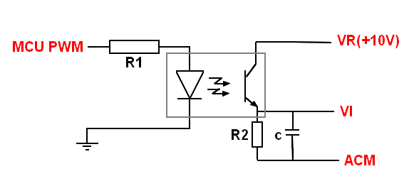
This takes only a couple of resistors, a small capacitor (in the order of some microfaradays) and an optocoupler (PC817 is cheap and widely available). Only need to calculate the correct resistor values depending on the voltage of your PWM pin and the VFD reference values. The optocouple isolates the board from the VFD.
This is an example for the Huanyang driver.
This circuit can be used on other VFD that have any kind of analog input control and replaces your potenciometer.
According to the manual Jonathan provided in his initial post, his VFD has a 5V analog input as well as a 10V input, so for this specific VFD, he should not need an optocoupler (unless there is some strong reason to isolate the VFD from the control board?).
Recently I tried using an optocoupler on fan pins on my Rambo board (ground side switching), and I was not able to get it to work the way I wanted. According to the voltmeter, I was not getting full voltage, and it operated in reverse (255 was fully off).
It was also interesting to me, that according to his manual, the VFD has separate settings for the use of a potentiometer vs. 5V analog in. To me they would be, as you indicate, interchangeable.
Adding a circuit like this makes you loose a bit of range.
This one is non inverting. With the optocoupler shorting to ground is the version that inverts it.
I believe im going to go for just the screen and a Potentiometer for now. Already have all of that on order. Once i get back in town i will attempt to model up a nice case for them and 3d print it. I may try to add in Gcode with a switch later but i honestly think that just having a screen to see it and easy adjust i will be just fine. Now i just have to figure out the code and model the case lol.
Edit… The more i think about this i might like to have marlin turn the spindle on and off. Not actual rpm settings just on and off. If i understand it correctly there is an input for that as well. Hoping some of you more educated guys can make sure im correct. Im not sure if i will have to run that though the Nano or if that can come straight from my SKR Pro. Turning it on isn’t a problem obviously. But often times my attention is scattered around the garage while the machine is running. Im out there and watching it but not staring at it. So it would be nice for if a tool change comes up or the job ends for it to turn the spindle off and that will alert me for the next step if im not paying 100% attention to it.
There is a RESET connection but there is precious little info on what that does. If you are going to use an external potentiometer to control the spindle speed (Pn03=1) then I think I would have the gcode operate an external single channel relay that disconnects the 5v_out line from the potentiometer which will pull the 5v_in signal line to ground, that should stop the spindle. If you are going to use the controller to set the spindle speed (Pn03=3) then it will stop the spindle automagically at the end of the job without needing a separate relay. You can configure Marlin to use either mist or flood coolant and define (for example) pin PC4 and use one of these to do the job. Use M7 and M9 to start/stop the spindle if you used mist coolant and M8/M9 to start/stop if you selected flood coolant in configuration_adv.h
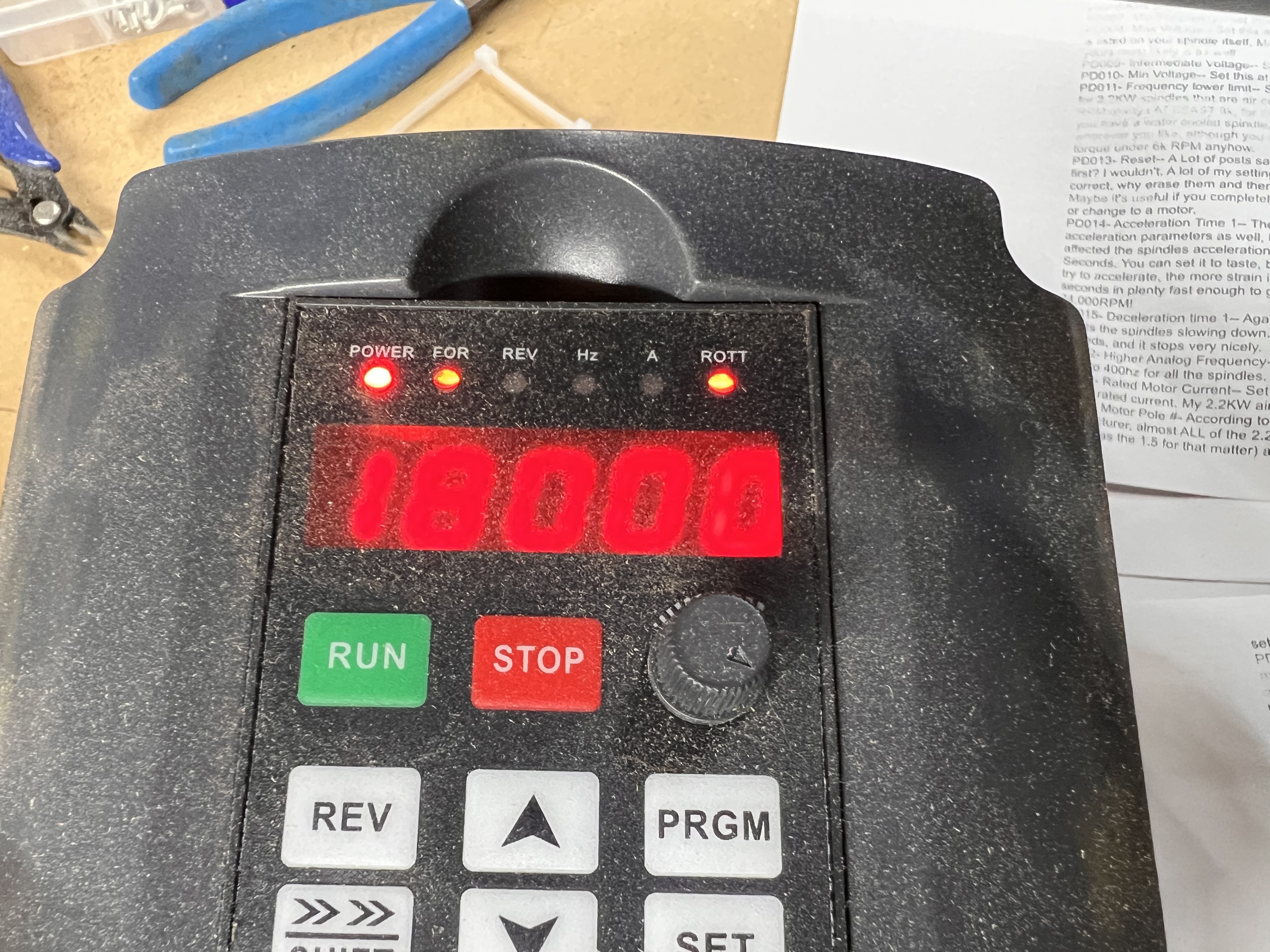
I still plan to make the screen for this one since where I want to mount the vfd isn’t in the best location to see it. I haven’t had a chance to mess with the one on my primo yet. But hopefully it has it as well lol
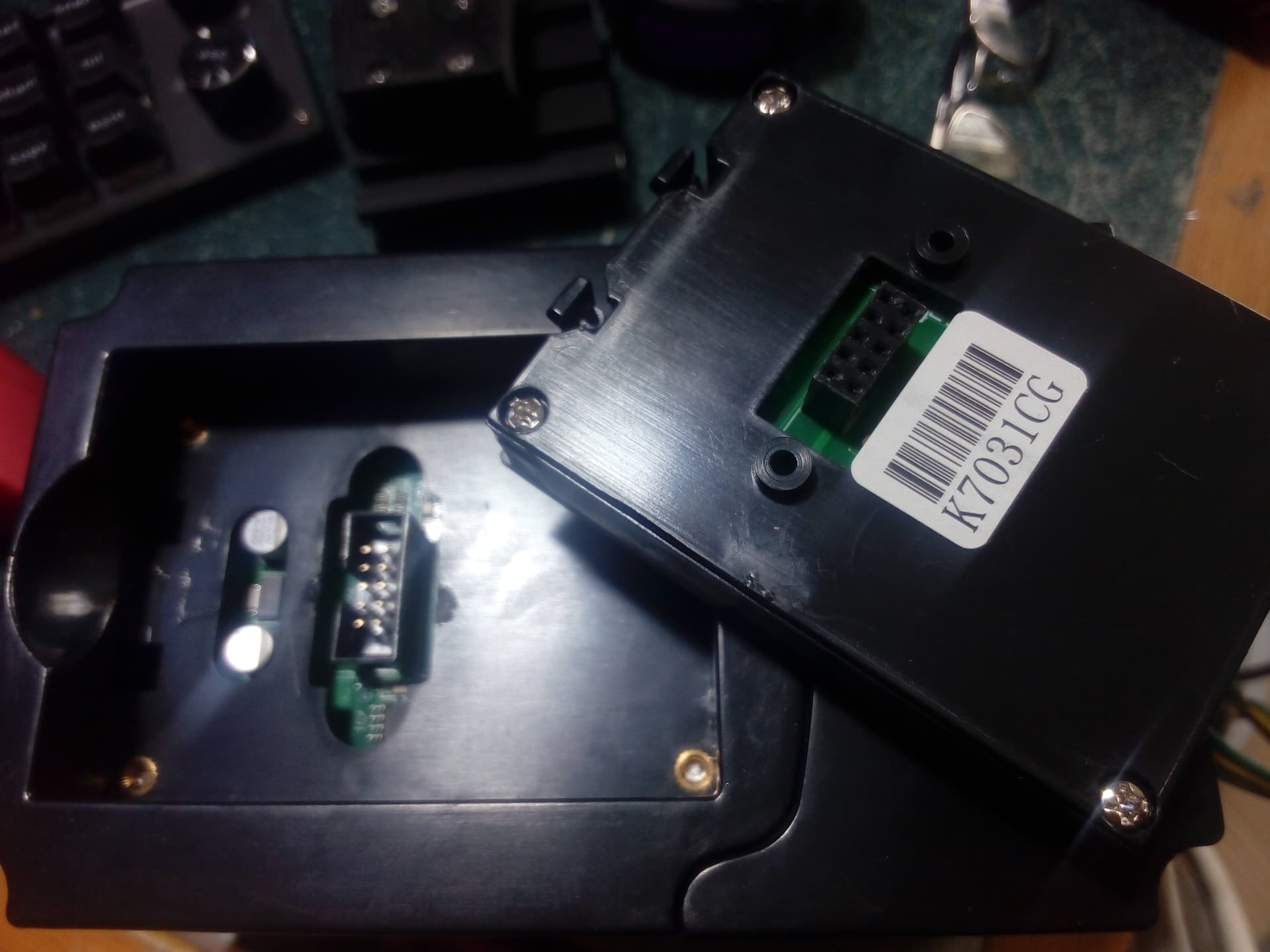
The display on your VFD is removeable. There are two ‘types’. one has a standard 10way ribbon cable into a socket on the display and the other just has the plug and socket - either way, you will just need a 10 way IDC extension lead.
@Jonathjon
What temps do you get from your spindle?
I’m getting the same spindle but just wondering if my PETG core and holder will be handle the temps from the spindle?