Hello I would like to install a laser with 3 wires 12v, + - and signal connections on a SKR PRO 1.2 with 6 x 2209 motors and a TFT35 E3 v3 on a 2 cnc lowrider!
I would need the connections to the card and the firmware configuration to add!
Hi
I have exactly the same configuration and the same project : try to connect a 15w laser (optical power 5.5w, 12Vin, PWM 5-12V). I looked everywhere for a document showing the connection, no way…
in the forum, I read this :
12V + and - ->> SKR power (+,-)
PWM ->> fan0 (-)
The problem : when i connect the laser on 12V (+PWM on fan 0), as i press the laser button ON/OFF → it burns
Does somebody could show us a connection diagramm or some connections photographs ?
Thanks a lot !
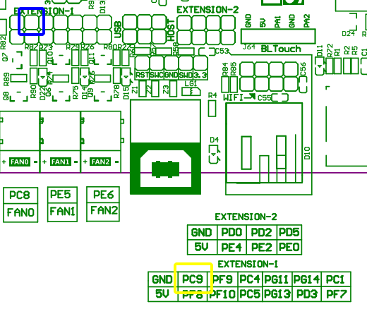
Driving a laser with the 12V pin is usually more complicated than using a 5V or 3.3V pin. It usually requires extra circuitry like the SSR used in the topic referenced by Olijouve. The problem is that 12V often have the PWM implemented on the ground side rather than 5V side of the pin pair. Assuming your laser will handle it, the better solution is to use a 3.3V pin. Usually, a laser that is rated for 5V PWM input will also accept 3.3V input. Assuming you are using a later version of the V1 maintained Marlin firmware (V510 or later) for your SKR Pro board, laser control is enabled, and the laser pin is PC9 (framed in blue in the following graphic).
Hi
thanks for your answers ! I will check Mperino solution.
This is my configuration today :
MARLIN (“V1CNC_SkrPro_DualLR_2209 - 2.0.9.2 - 513DL”) :
//#define SPINDLE_FEATURE #define LASER_FEATURE #if EITHER(SPINDLE_FEATURE, LASER_FEATURE) #define SPINDLE_LASER_ACTIVE_STATE HIGH // LOW // Set to “HIGH” if SPINDLE_LASER_ENA_PIN is active HIGH
#define SPINDLE_LASER_USE_PWM // Enable if your controller supports setting the speed/power #if ENABLED(SPINDLE_LASER_USE_PWM) #define SPINDLE_LASER_PWM_INVERT false // Set to “true” if the speed/power goes up when you want it to go slower
//#define SPINDLE_LASER_FREQUENCY 2500 // (Hz) Spindle/laser frequency (only on supported HALs: AVR and LPC) #endif
AND I USE A FUSION 360 POST PROCESSOR (->github.com-guffy1234-mpcnc_posts_processor) :
Group 4: Laser/Plasma related
Laser: On - Vaporize|Persent of power to turn on the laser/plasma cutter in vaporize mode|** 100||
Laser: On - Through|Persent of power to turn on the laser/plasma cutter in through mode|80||
Laser: On - Etch|Persent of power to turn on the laser/plasma cutter in etch mode|40||
Laser: Marlin mode|Marlin mode of the laser/plasma cutter ()|M106|M106 S{PWM}/M107 = 0; M3 O{PWM}/M5 = 1; M42 P{pin} S{PWM} = 2;|
Laser: Marlin pin|Marlin custom pin number for the laser/plasma cutter|4||
Laser: GRBL mode|GRBL mode of the laser/plasma cutter|M4 **|M4 S{PWM}/M5 dynamic power = 4; M3 S{PWM}/M5 static power = 3;|
You don’t describe what problems you are having or what questions you want answered. For the firmware, laser support is already enabled, so you should not change anything from what V1 setup.
I’m not sure what this means. With the V1 firmware and the pin I specified, both M3/M5 and M42 should work to send the signal to the laser. With LightBurn, you want to use the “inline” option to drive your laser.
I’m not sure of your wiring. If you give the brand of your laser and/or a link to an online reference for your laser, someone might be able to give you guidance for hookup. For input from the control board to the laser, usually it is only two wires: a ground and a signal line. Sometimes there is a third enable line. If you need the enable line, the pin is defined as follows:
#define SPINDLE_LASER_ENA_PIN PB0 // Heater2
Usually, the laser is powered by a separate power supply, and often requires care if you attempt to pull the current from the control board.
Sorry for my English, and i can only post 1 image, one by one…
This is the laser (bought on VEVOR, 15w laser) → I already ask for the manual (now answer yet)
I don’t know how does the PWM signal work. My laser has a switch button ON/OFF : what is the good position to make it working with PWM signal ? When OFF → only the laser fan is running; when I press ON, the fan slow down, and the laser burns non stop…
I don’t now how to connect the laser to the board. And I would like to know what is the easiest way or the more obvious way to connect the laser to the board, please.
If the “Mperino” configuration is THE way to connect the laser, I will try too do the same.
But need : change Marlin config, buy an SSR DC (do you know which model ?) and add a resistance.
I hope to be more understandable, thank you for your time.
There are some unknowns here with respect to hooking up your laser. The biggest is what voltages of PWM will it accept. If it can handle 3.3V or 5V PWM signals, then you have a good shot of hooking your laser up without any additional electronics. I searched the VEVOR website and did not find your laser module. I’m assuming it is powered by 12V. I suggest this recipe:
Use the firmware from V1 unmodified.
Have the laser switch in the off position.
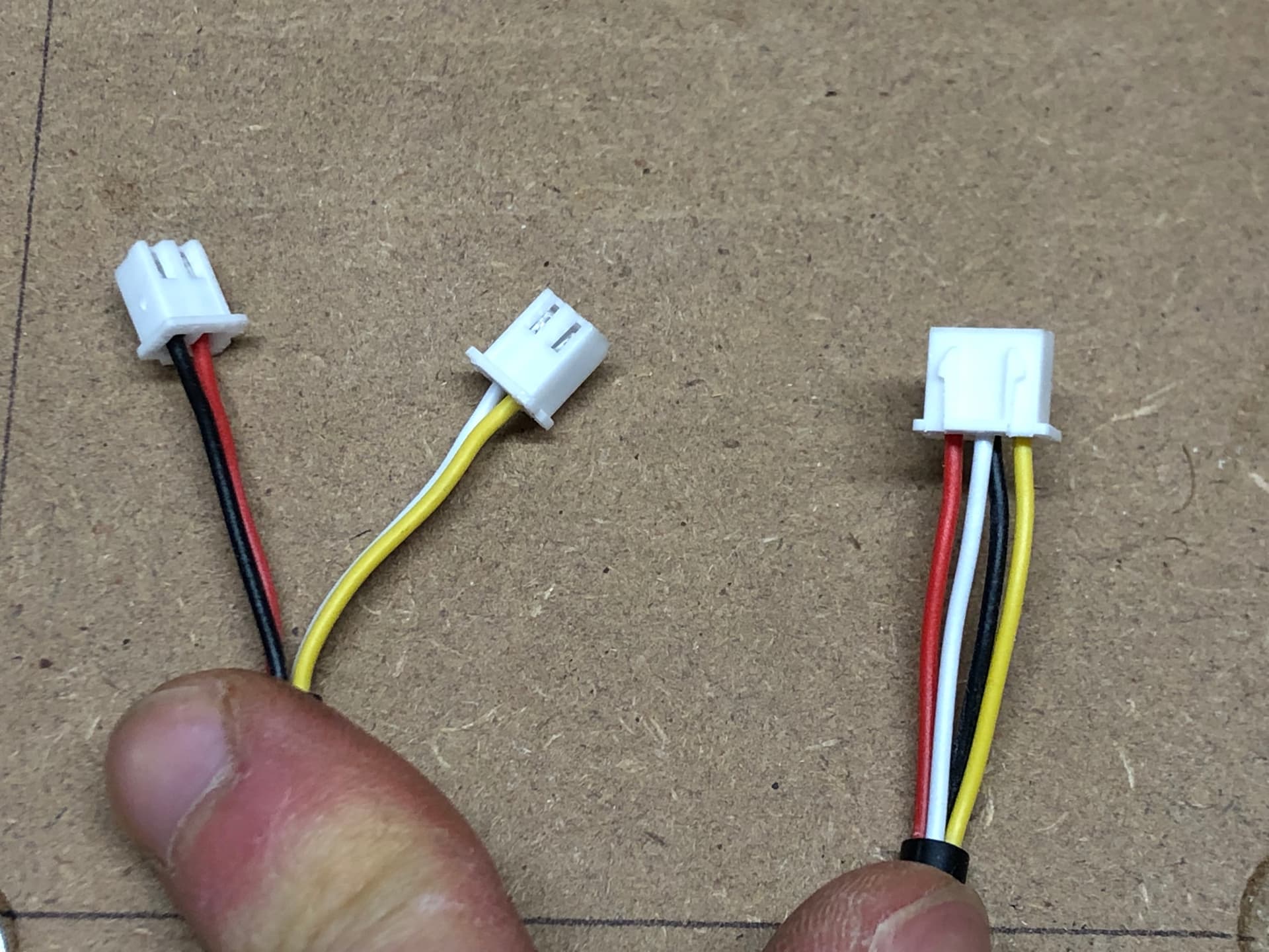
Use the 2 + 2 → 3 pin cable
Supply 12V power from a second power supply to the black and red wires. Don’t try and draw power from the control board. Red will be positive, and black will be ground.
Plug the yellow and white wires into the PC9 pin and the ground pin just to the left in the picture I provided above. I cannot clearly see the connection, but I believe the white wire is ground and the yellow is the signal that should be connected to PC9.
Test with the g-code file attached to the first post in this topic.
It works !
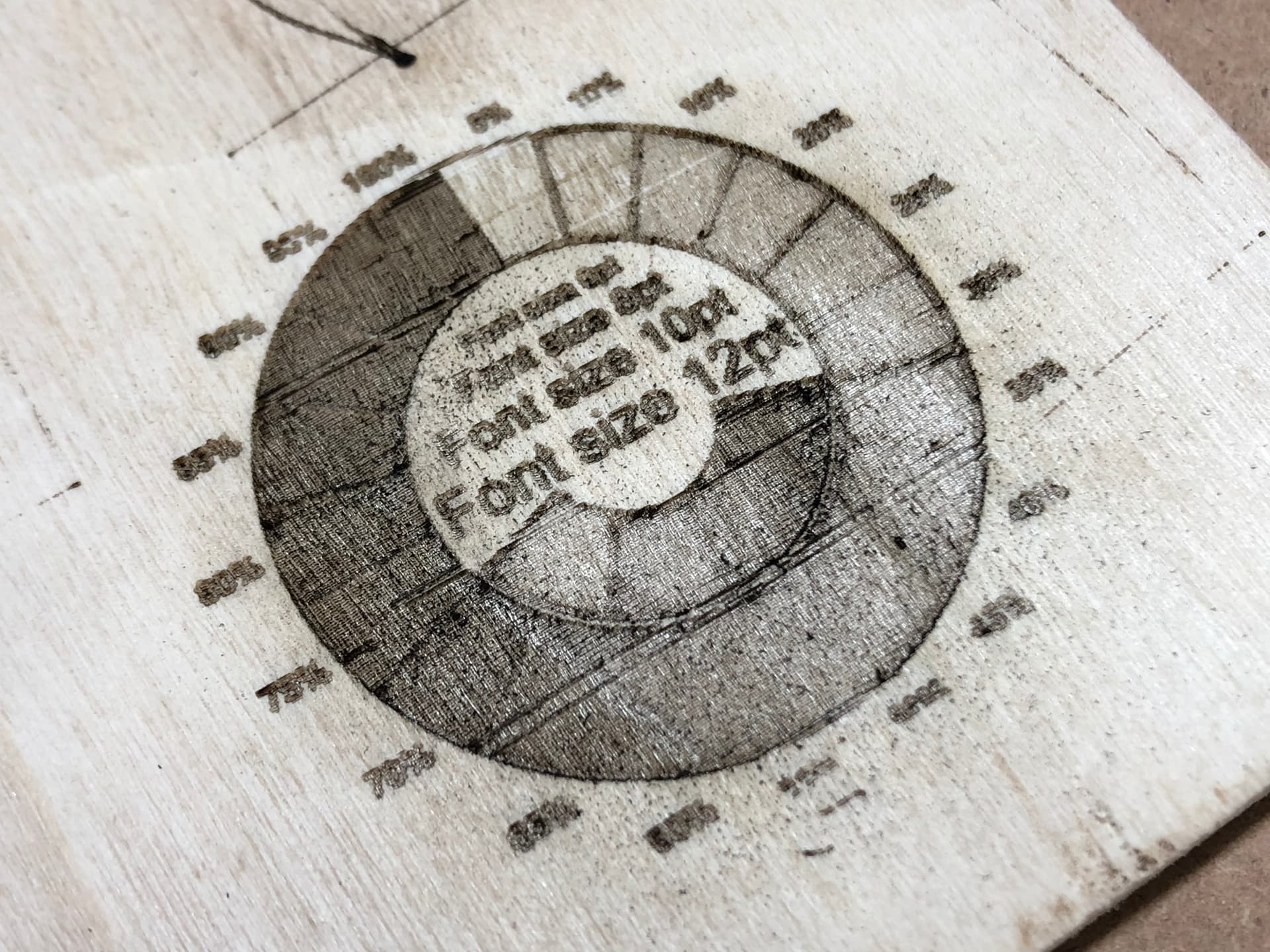
I connected everything as you said, except the push button (I push it → the yellow DEL switch to a BLUE one on the top of the laser - switch TTL/PWM maybe ?).
Thanks for your advice, this is the result →
Now, I need to find a way to export a my own gcode with Fusion 360 (but the laser post processor from guffy1234 doesn’t seem to work for me…).
I read the gcode (of E2 engraving test), but I didn’t find indication about the PWM (only a M5 code at the end ??)
I will do some tests tomorrow
Thank you very much and will try to post some images very soon.
LightBurn is a must have when working with laser, it is far more efficient than Fusion.
Give it a try, you have 30 days free, then it costs 50$, but that software really worth its price.
I read the gcode (of E2 engraving test ), but I didn’t find indication about the PWM (only a M5 code at the end ??)
The laser strength can be controlled by inline codes. It uses the ‘S’ parameter in the G0, G1, G2, and G3 codes. Full power PWM is 255, so if you look at this line in the file you used:
G1 X34.01 F3180 S70
…you see ‘S70’ The laser is set at 70/255 power…roughly 27% power. In addition, M3 and M5 should also work, plus M42 works to directly turn the pin on and off. I don’t think the Fusion 360 post processor supports inline laser PWM codes.
I second @Olijouve touting of LightBurn. I frequently using Fusion 360 for my design work, but export the finished pieces as DXF files and do the cutting in LightBurn. LightBurn does support inline commands.
I’m not sure it makes any difference for laser cutting, but Don Gamble has made significant improvements to the Fusion 360 Guffy post processor. You can find a link to his latest release here.
Hi
I try to configure lightburn and do some tests.
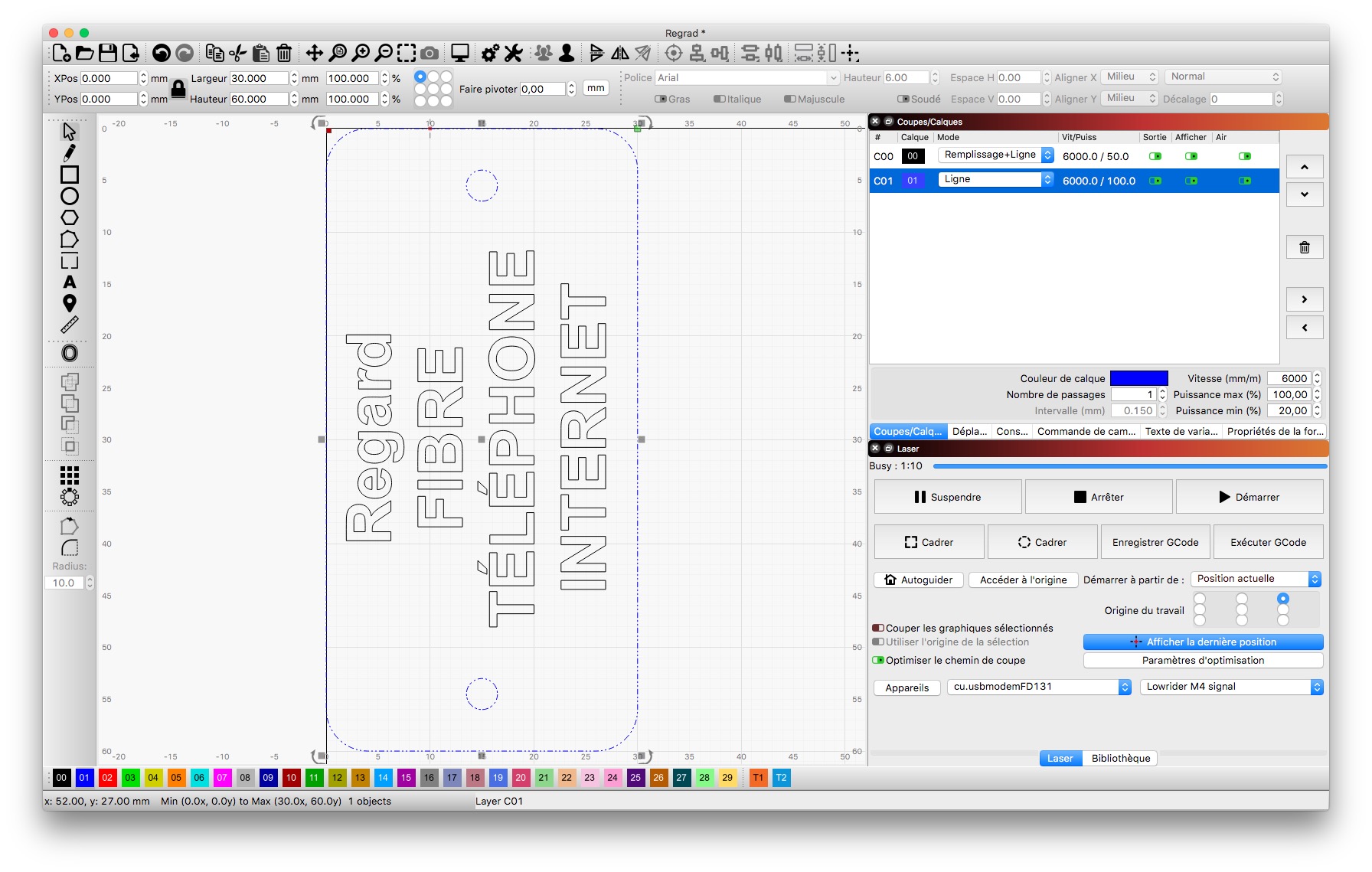
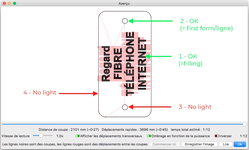
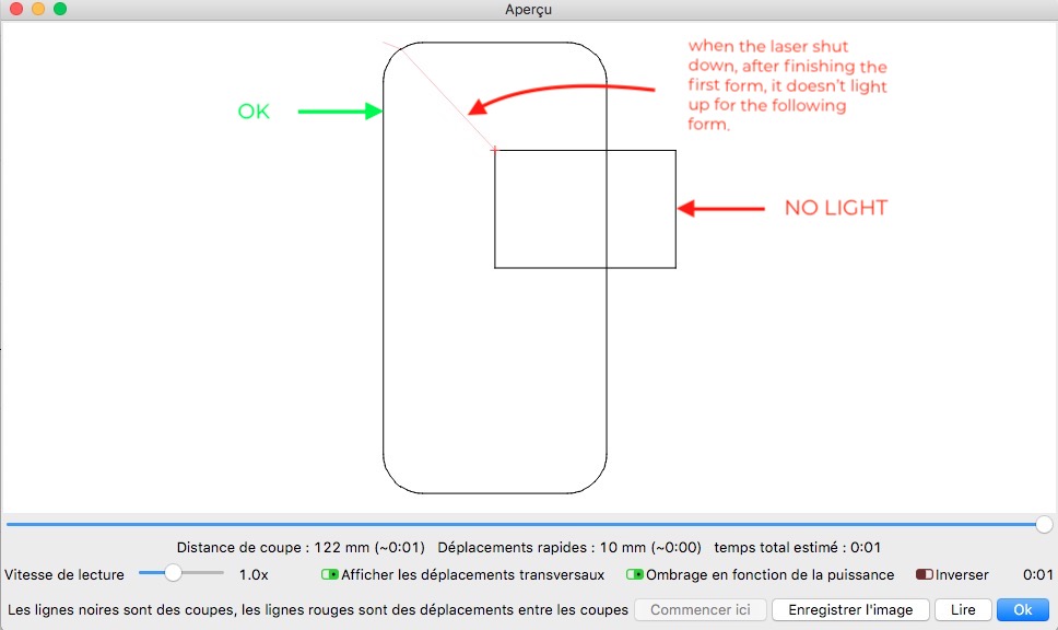
Problem → when I start a cut from lightburn, the laser works only for the first form, and there no power for the following form ??
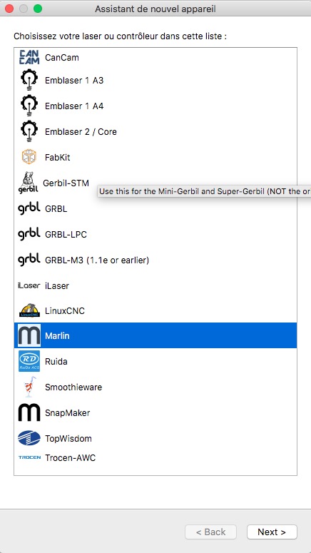
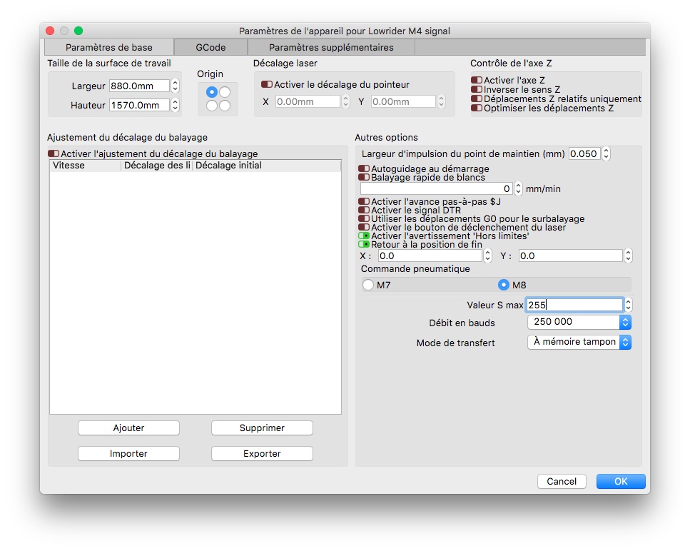
A problem in the parameter ? I look to the controler (Marlin ? GRBL M3 ? GRBL M4 ? GRBL LPC ?) what is the good one (M4 I guess ?) - but doesn’t work.
A problem in the baudsrate maybe ? Which one is the best ?
Thank you for your help
LightBurn has an option to cut only selected path or all forms on the screen. it’s on the laser tab, same tab where you choose origin.
I think default behavior is the selected path.
Did you select more than only one form ?
Did you create the design within lightburn or was it an import ?
If imported check at line weight, if a line is to thin it can happen to be ignored by lightburn.
Also did you try to enable « couper les graphiques sélectionnés » ?


 ??
??