OK, This is meant as a summary of all the helpful stuff that I got from several posts. So I’ll post a link in a few of them pointing here, rather than dupe clutter each of them.
I got 2 different lasers working on SKR Pro with Marlin 2.0.7.2 (specifically SkrPRO_DualLR_2209-2.0.7.2.src ) from the link: SKR Pro - V1 Engineering Documentation
Unzip the file, and unzip Marlin.
I edited Configuration_adv.h to:
//#define SPINDLE_FEATURE
#define LASER_FEATURE
#if EITHER(SPINDLE_FEATURE, LASER_FEATURE)
#define SPINDLE_LASER_ENA_PIN PF9 // Turn Laser OFF/ON using PIN PF9 on Ext1
#define SPINDLE_LASER_PWM_PIN PC9 // PWM Controll Power Level of Laser on PC9 of Ext1
#define SPINDLE_LASER_ACTIVE_STATE HIGH // Set to “true” if the on/off function is active HIGH
#define SPINDLE_LASER_PWM true // Set to “true” if your controller supports setting the speed/power
#define SPINDLE_LASER_PWM_INVERT false // Set to “true” if the speed/power goes up when you want it to go slower
The physical Components I needed other than the Laser:
1x 200K-220K OHM Resistor
1x DC SSR (any one that will trigger on 3.3vdc in the Input and handle 12V DC on the Output)
1x Push Button Micro Limit Switch (12.6× 6.5× 5.7mm)
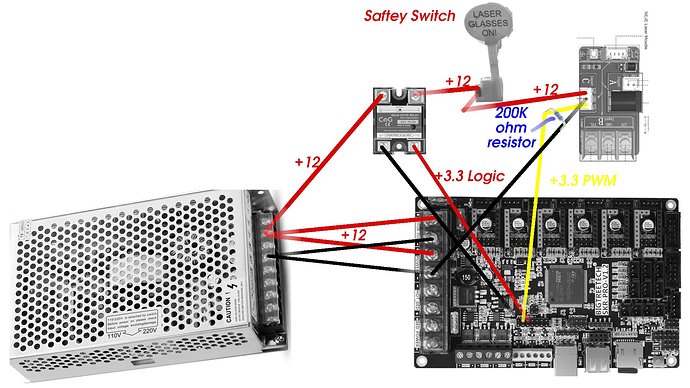
Here’s the connection diagram:
Close up of EXT1, Black(GND) Yellow(PC9 aka PWM) , Red (PF9 aka ENA aaka POWER OFF/ON)

Double and Triple check that you are not putting the +12 to your Laser’s PWM PIN!
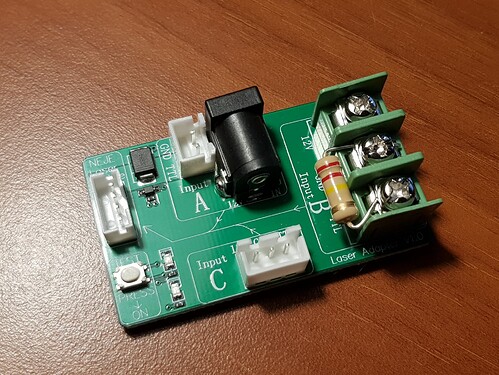
So what this does is output on a 3 pin connector (many lasers), +12v for the Laser, +3.3v PWM for the control, and pulls down PWM to give a clean circuit.
What this does is output +12v, GND, and +3.3v PWM on a 3 pin JST connector. It is Common GND, with a Pull Down resistor to damp any spikes from the board.
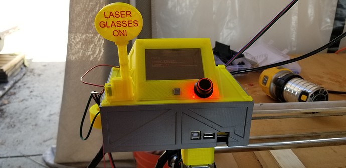
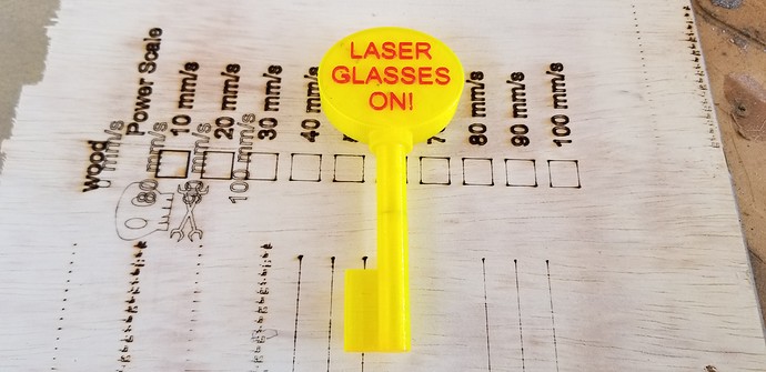
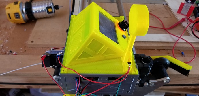
There is also a Saftey Interlock (kill switch/reminder to put on goggles). I’ll upload .stl’s/.3mf’s for the case mods (once Im fully happy with them).
Here’s it with the Interlock Key inserted:
Interlock Key:
Side View (gonna clean up placement of the SSR, and move it inside the box:
 . Using the information you have provided, I started looking for a NEJE laser on amazon and I found this one: