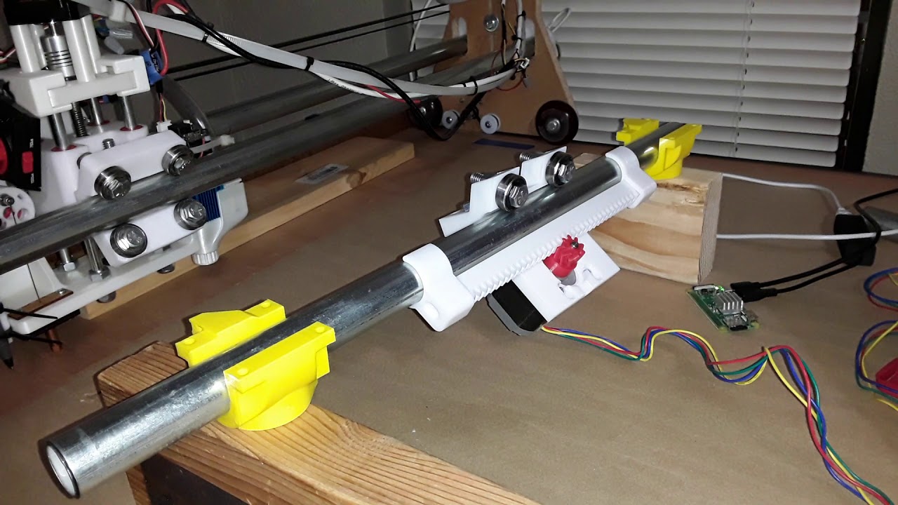
Printed R&P X/Y drive for MPCNC

With Peter’s “Epoxy Rack” thread, I found my interest in a printed rack and pinion drive piqued once again. But where Peter is working on a cast epoxy rack, I wanted to resurrect and play with the r&p setup I’d used for my Phlatprinter-inspired foam cutting machine… and adapt it with possible application for MPCNC.

I played with Peter’s Openscad design for a while and printed several parts for fit check… only to discover that his design was for 25mm OD tubing. After a few cursory attempts to adapt it for 23.5mm EMT and reconfigure for a printed rack, I finally decided to start from scratch using Onshape, my CAD of choice, and spend my time more wisely. So after a few “fits and clearances” prints I finally have a [kind of] working prototype…

Operation is a bit rough yet… hopefully due to the mix of quick and dirty new parts and a few previously printed parts from the Phlatprinter project.

Having built a number of machines using rollers similar to Ryan’s MPCNC parts, which were sometimes rather painfully adapted to the task, I also decided to see if I could simplify the process by using a modular approach. Starting with a simple sketch to get the basic dimensions and configuration…

I came up with a 25mm thick “module”…

which was the replicated three times in a linear array…

and then “masked” with a sketch to extrude/remove the unwanted “outriggers”.

Then a channel was extruded/removed for the gantry tubing

and the roller portion is essentially complete. A gantry clamp will be added later.

Finally I added a mount for the motor that positions the pinion relative to the rack, residing directly under the EMT rail, and came up with the basic r&p drive configuration.

A number of design tweaks need to be made yet, to make it smoother and more workable, but overall I’m pretty pleased with the basic configuration. I also need to make the parts more printer-friendly and minimize the need for support.

In parallel, I’ve also got a new Prusa i3 MK3S build in progress and think it would really be nice to break it in and use the pretty silver Prusa filament supplied with the kit to build a whole new MPCNC with r&p drive. Hopefully I can whip the parts into shape using my current MK2S printer and the crappy-green filament seen on this prototype… before committing to using the new machine and filament.

More to come…

– David

10 Likes

That’s fascinating. Thanks for showing the development process. Will be neat to see how it all works out.

1 Like

My only suggestion is mount the motor in the same orientation as the standard MPCNC or you’ll likely have issues with dust collecting on top of the motor. Wood dust + friction = fire.

1 Like

I love all these ideas. Here’s another one that’s a little crazy but maybe inspires something else that might actually work. Four 608 bearings and one rack/pinion:

motor_5th_wheel

The thing that got me thinking in this direction is the idea of radial pre-load to reduce backlash. This is somewhat of an abuse of the motor as load-bearing, but the vast majority of the load should be vertical. The gantry rails should see no axial load, so maybe this can work with an appropriate flexure that keeps the loads from getting too high on the motor.

3 Likes

Looking good!

I spent a couple of days thinking about how to arrange the stepper, rack, and bearings. This is my current preferred design:

The gantry tubes are below the frame tubes here. There are two bearings on the top, which can be used to tighten everything up (by reducing the distance between them using bolts that are not shown). The three bearings close to the stepper hold the tank thread.

There are a lot of considerations going into a design. You need to take into account at least these aspects:

  • Weight of the gantry (load on top of the frame tubes)
  • How to tighten things so the bearings grip the tubes without binding
  • How to make sure the pinion / tank tread properly grips the rack without too much tension and without backlash
  • You don’t want dust / chips to stick to the rack (so not at the top)
  • You want the rack as close to the gantry tube as possible to prevent the roller from rotating / racking
  • You want to adjust the tension on the tank tread (not relevant in the pure rack and pinion setup)
  • I’m probably forgetting a few things.

Looking at you design, I think you’d need a way to adjust the stepper motor to move closer or further from the rack. Ideally you’d put the rack higher, close to the gantry tube, but I think that would not make that much difference.

Also, I think your rack is kind of free to rotate around the frame tube and move along it. I’d clamp it more tightly be using a couple of screws both above and below the frame tube.

But so far so good. I know it takes a while to design a nicely working roller, well done!

2 Likes

I hope that wasn’t too horrible. I generate the OpenSCAD code using another language (I wrote my own library in Haskell). I never looked at the OpenSCAD code it generates, but it’s probably full of duplicate code and very hard to follow. Hopefully you were just looking at the result in the OpenSCAD GUI.

1 Like

Since you brought it up, I could tell that it didn’t seem “hand-coded”. No comments and totally lacking in the “beautification” department. But it seemed to work… and using the “scale” function I was able to get most of it to work for 23.5mm tubing. But when I started trying to reconfigure for my printed r&p, I finally decided it’d be a lot easier to do in Onshape. I like Openscad… but this would’ve taken way too long and been far less suitable for sharing. But I rather enjoyed messing around with it for a few days anyway… :grin:

1 Like

I recognize that I didn’t put in many adjustment and design features in my previous quick and dirty demo roller assembly. I did a number of mockups and took pretty close measurements to put most everything in its approximate location and was primarily interested in a basic configuration and function. Thank you all for your input.

Jamie’s diagram struck a chord with me in particular… so I fired up Onshape and started another roller assembly based on his idea. This is what I came up with…

26%20PM

I finally massaged it to where I thought it should function well enough to demo the concept. Please know I’m aware the roller assembly is not hanging in its proper orientation… but it actually helps to see everything a bit better when operating this way right now. Once another roller assembly is hanging off the other end of the gantry rail… it should be just fine.

A few photos of the bits and pieces…

20200119_181908

20200119_192124

20200119_203540

20200119_203557

20200119_203621

It is considerably more positive and smooth in its movement than the previous assembly… I think primarily due to the solid backing of the rail against the rack. It still needs a design tweak or two to get the pinion and rack to mesh a bit more squarely but, all in all, this looks to be worth pursuing further.

I am not, and never was – even when I did this stuff professionally – a rigorous engineer or designer as some of you are… so will depend on you guys to tell me if I’m too far out in the weeds. But if nobody hollers I plan to continue down this path and see where it takes me… :thinking::roll_eyes:

6 Likes

I like where this is headed!

Can you feel any slop in the gear interface? Only time I had used herringbone gears was back on an old wades extruder but I was setup funky and didn’t align well.

1 Like

I haven’t play with the demo setup enough to see a whole lot… and it still needs a few alignment tweaks to be ready to use on a machine. But I did play quite a bit with the herringbone r&p on the Phlatprinter-inspired machine from before. No measurement of “slop” or anything… but the Vicious logo seemed to print well (even running over the joint in the rack) in this video I’ve shown several times in the past…

The ~8" rack sections (up to 40 teeth IIRC and largest I can print) have a 1/4" hole through the middle and you can string sections together on a length of threaded rod. Butted against the rail and tightened appropriately, I’m hoping the seams will never be noticeable. Another neat thing with the herringbone setup is the rack and pinion stay in almost perfect alignment.

Fun stuff to play with, for sure! – David

4 Likes

Getting closer to having a complete axis built…

The rack sections are printed with a 1/4" hole through the center… which allows multiple sections to be put on a threaded rod to build up whatever length is needed. Onshape screenshot and photos of rack detail…

Later…

2 Likes

At what point do we start considering just replacing these with corner mounted steppers and using leadscrews?

I guess cost would be the limiting factor there. 4 - 1000mm leadscrews are ~ $100

IMO leadscrews are old hat… done a bunch already. And that kinda misses the point of this exercise, doesn’t it? :wink:

1 Like

A complete axis? Actual travel shown here is 360mm…

I’ve tried to honor the outer rail to gantry rail distance and make the roller assembly a drop-in replacement for the MPCNC roller… thinking that if I ever feel brave and frisky enough I could just swap out one axis on either of my two working MPCNC’s, “Joe” and “Henry”. But being commemorative and calibrated, I’m really not leaning that way right now.

OTOH I have my Prusa MK3S build underway and really need to get back on it. I’ve let it slide for a few days and had thought at one time how neat it would be to break in the new machine and devote the roll of silver Prusa filament that came with the kit to a new MPCNC with the R&P drive for X and Y, if it should work out okay.

I think I’ll just mull it over for a few days, while I finish up the printer build, and buy some time for feedback from any of you guys who’ve shown interest in this project. It’s been fun and I’d love to hear any thoughts and constructive comments any of you might have!

– David

6 Likes

This is fascinating. Given my current issues with belts and binding, I’m tempted to ask for STLs so I can print out a set and try it on my not currently functioning build.

Thanks for the kind remarks but please know that this little project is in no way an attempt to undermine Ryan’s MPCNC design. His design is robust and proven and is the ONLY way to properly build an MPCNC. Please use the forum to work out your issues with belts and bindings… you’d only have a whole new set of problems with this drive system. There is no one – including me – willing to support this unproven design… it was simply an attempt on my part to satisfy a particular curiosity I had about a printed r&p drive system.

– David

Not trying to undermine Ryan. He’s actually provided a bunch of help in troubleshooting my issue. I just find the idea of this whole thing fascinating.

Gotcha. I’m sure you’ll get the belts/binding issues taken care of… there are literally thousands of MPCNC machines out there in the wild that work just fine with the belted setup.

Yes it is fascinating. That’s why I pursued it. Tired and retired, there’s still enough “engineer” left in me that I find it satisfying and great fun to play with novel ideas. Just trying to stay “sharp” for as long as I can… :stuck_out_tongue_winking_eye:

That is awesome. There is quite a lot of acceleration at the start and end. It makes it look a lot smarter :slight_smile:

Are the steps/mm the same? I assume they would be a little less because the pulley is larger, right? Is the other end free wheeling?

That’s very fun to watch, and I like that it is 3D printed. I hope you had fun making it.

1 Like

Thanks, Jeff. I needed a board of some sort to demo the stepper and r&p and picked up a little Grbl-based Eleksmaker Mana 2-axis board I had on a minimalist machine I had recently built. Just so happens the steps/mm seemed pretty close as is… when I check they were set to 80 steps/mm. Since I was primarily interested in smooth movement for demo purposes… I did nothing absolutely nothing to any of the operating parameters. Don’t you just love it when a plan comes together? :wink:

Edit: no free-wheeling… there are steppers on both ends running in sync.

1 Like