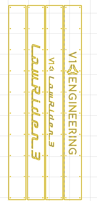
I’m having some challenges in “nesting” drawings into a material sheet prior to creating gcode in CAM (EstlCAM)
Fusion 360 doesn’t support nesting in the free version, and I’m not wanting to shell out hundreds of dollars every year for this feature.
EstlCAM doesn’t seem to have any nesting function, and adding drawings and manipulating them manually seems tedious and very imprecise. By that, I mean that each drawing needs to be moved into a position individually, and defining the exact distance between each item , or between the edge of the item and the edge of the material is challenging (although possible).
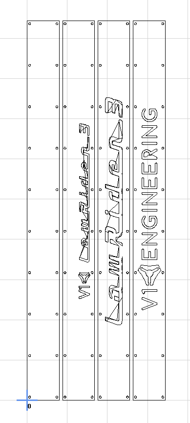
DeepNest IO, seems like a great idea in theory, but falls pretty short in practice. You can set diustance between items, but not between an item and the edge of the sheet, and you can’t set it to align at any edge other than the top left corner. Also it seems to mess up some drawings:
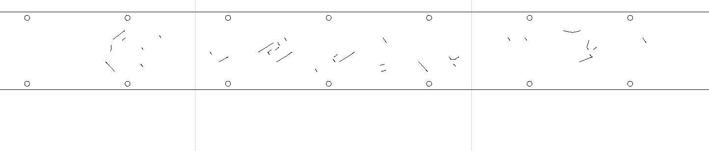
Note how the text on the Deepnest version is completely messed up (R in Engineering, pretty much all of the Lowrider text)
I would love to use Deepnest, even with it’s limitations on not being able to select edge distance, but the messing up of the DXF files seems to be a show stopper.
Does anyone have any other options or suggestions for nesting (that don’t cost a bundle)?
I usually layout jobs like that in CorelDRAW, and then export an SVG (or sometimes a DXF) and then import into ESTLCam, and it works as intended. There is a bug with exporting SVG from CorelDRAW in that if I choose different export settings (switching from SVG v1.0 to SVG v1.1, for example) I get butchered results. But SVG v1.0 with “drawing precision” set to 1:1, gives good results.
Currently I’m going: F360 > export to DXF > convert to svg > deepnest > export svg> cam software (usually lightburn as I’m mostly using nesting for laser cut)
I tried the directly imported version, and it works fine with a very small carve (0.25mm on both sides of the line), with no errors (recognizes the word as a single continuous line).
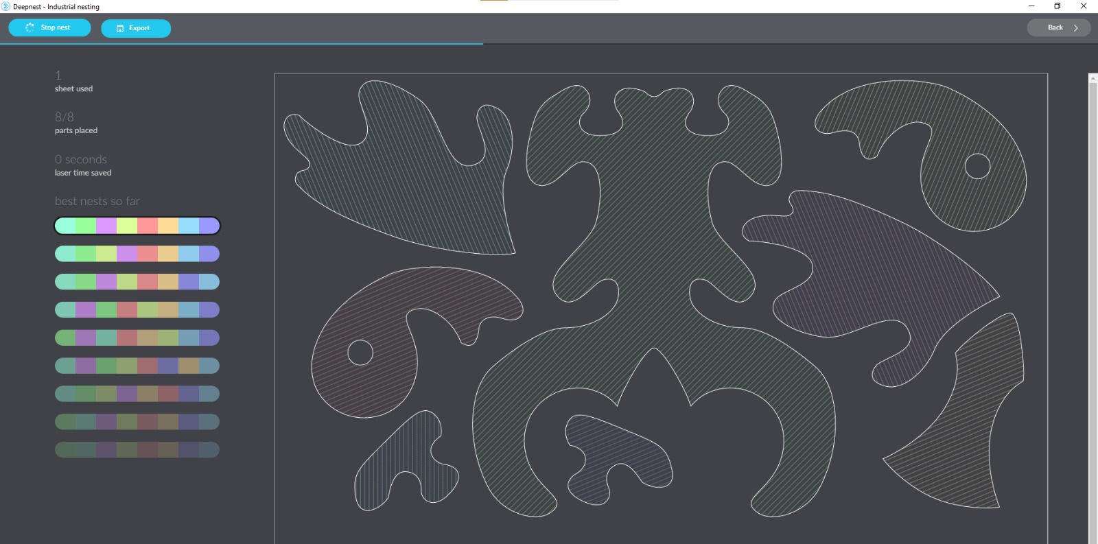
Yes, if I can get it to work on these drawings, it could be very useful! Trying to arrange and optimize the layout of multiple parts manually is a chore, this program might be a real game changer
Text always worries me. it gets converted from a font, then converted, and in this case converted a few more times.
I have used deepnest for other parts and it is crazy awesome. For things like the LR side plates I usually just duplicate my toolpaths though. On simpler parts deep nesting is great but I did not want to manually select 144 holes plus all the tabs and cutouts. So I do one set a then duplicate them alittle more than one bit width apart.
It doesn’t have a problem with DXFs, but it detects the slightest of gaps in the drawing that Estlcam doesn’t care about and then doesn’t recognize it. Took me a while to figure it out.
Edited after getting Deepnest to open the file, and after reviewing the original more closely in Fusion 360) -
Sort of (mostly yes, but with a caveat…). File size went from 129 KB to 2011 KB, and after 8 minutes Deepnest is still struggling to import (it finally opened after >10 minutes) Original file opens in less that 3 seconds.
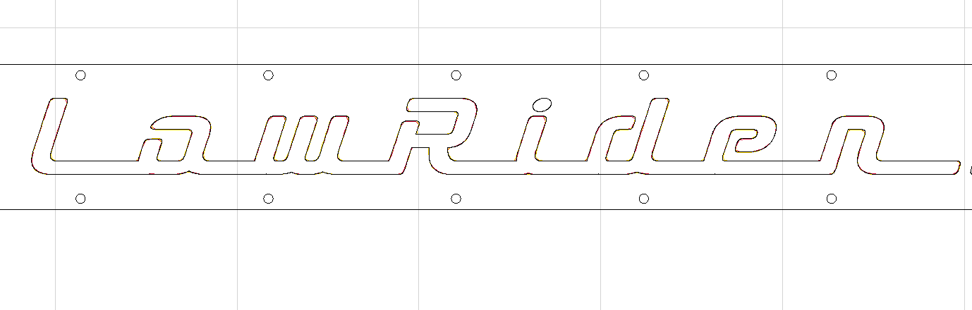
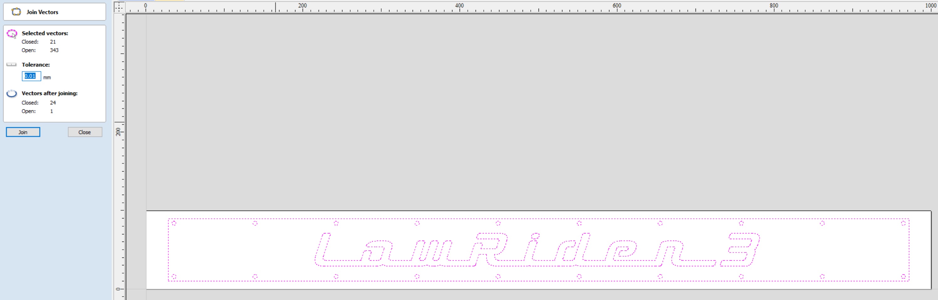
Once opened, it does seem that the text is fully closed, and it shows nicely without visible errors.
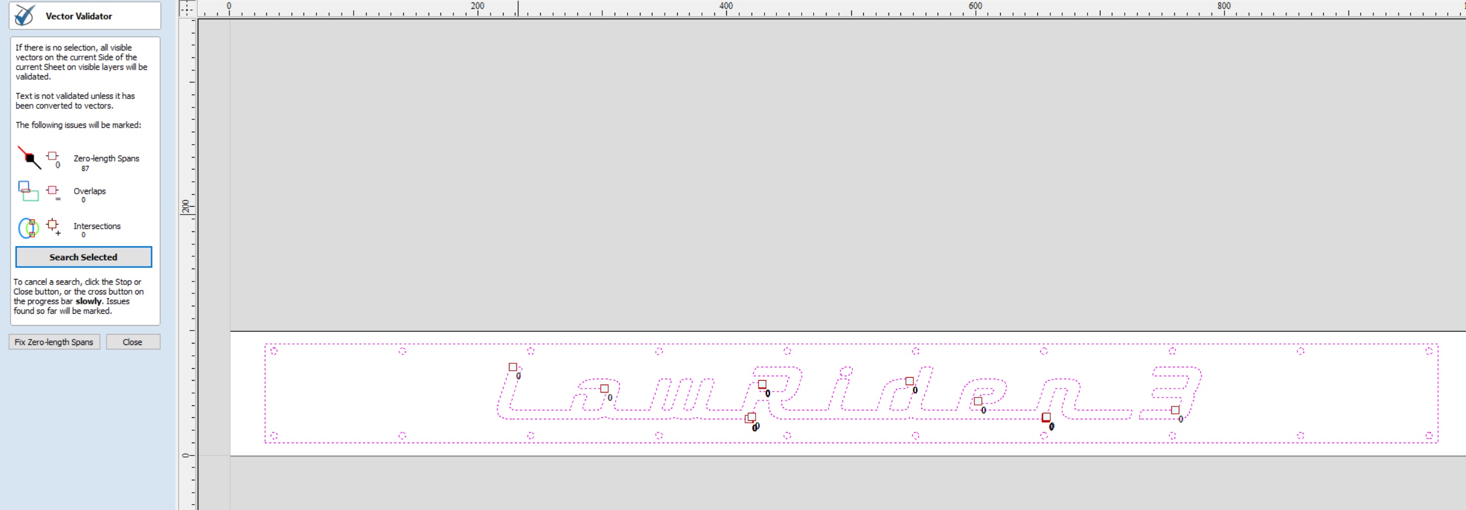
I am completely intrigued by the process that you used to identify and correct the errors. What program did you use for that?
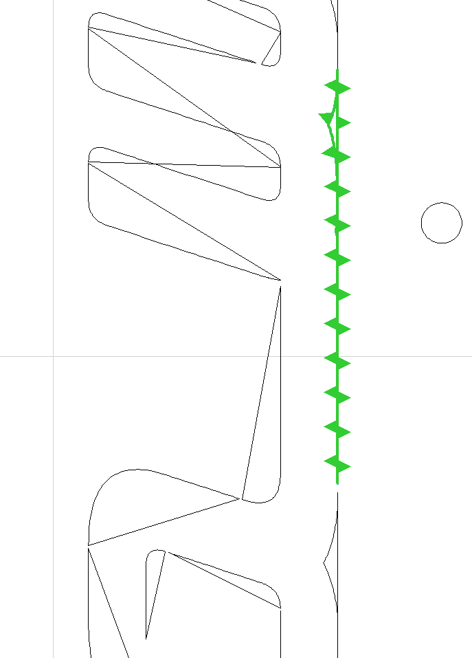
If I zoom in really closely in F360, it does show white dots at the end of every line, which reportedly means that the lines aren’t connected, but manually connecting them all seems like a very daunting task.
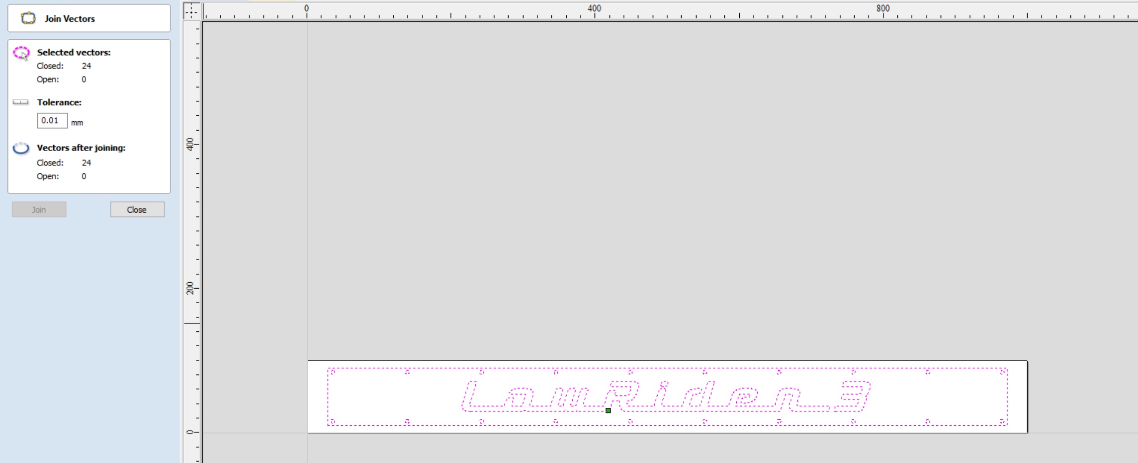
Okay, so the lesson I learned today is that even though a drawing looks like all the lines are closed, and even though EstlCAM recognizes and accepts it as closed, it may not actually be closed.
I have three files with errors (open lines) in the text section,. The text originated from someone else, and I simply resized and copied it into my blank strut template. I need to expand my skill set in the future to be able to figure out how to create the text sections myself, and how to connect the unconnected parts of the text sections that I already have.
Because I am currently able to accomplish what I want (which is to cut the struts on my LR3 using EstlCAM) by manually inserting the files and moving them around in EstlCAM, I will probably just continue on without trying to correct the lines at this time. If I come across an easy and quick way to fix the open vectors on all of the files, I may go back and try to sort that out and make it “correct” .
What I do know now, and will apply going forward, is to ensure that any drawings that I create myself have all of the lines fully connected (even if they look like they already are). That way I can use Deepnest to lay out and optimize the various parts on a single sheet.
Update - there is an add in for F360 called “Fill Gaps” that will supposedly correct these errors quickly and easily. It does require a license, but I’m not sure if the $10 cost is permanent or annually. I’ll report back once I get an answer from the developer.
Actually, now that I think about it, I imported the downloaded owl puzzle DXF into deepnest and it failed with multiple shapes missing as they were not closed
I imported it in f360 and extruded the shapes (f360 will recognize them as closed) and created a sketch over those extruded parts, which I exported to DXF
This dxf was ok when opened in deep nest
I had to convert to svg though because the units were off