Which slicer are you using? Can you show a snippet of the actual GCODE produced by you slicer for a print?
What gets produced should be something like the line below from one of my own prints: M190 S54
That tells the printer to heat the bed to 54C and wait for it to finish heating, leaving the bed heater on at that setpoint.
After this, you should grep for other M190s in your generated gcode to be sure there isn’t something in your slicer config changing the set point (for example if you have a first layer temp of x and after that it gets set to 0)
Prusa slicer filament setting says bed is set to 40 °C.
The gcode preamble is set to call START_PRINT from klipper and the start print macro code is what I included above. I’ll post gcode from the actual file when I’m back in front of the printer.
I just hooked up v1 of that sensor and bought some V2’s. I think this is pushing me quickly to Klipper. My printer works perfectly in Marlin mode on the screen, That stupid TFT interface injects so many commands I get all sorts of random issues. So I am sticking with Marlin mode on the screen until I switch to klipper.
The sensors though…I wish I would have done it sooner. Snags, snarls, lumps, or run out, or that bent end of the spool, they all quickly trigger a pause and eject. I know it says 2.88mm, but that is the worst case, it typically catches it way sooner.
*- edit- and with klipper you can use the secondary internal switch to trigger the end of the filament and tell it to keep driving far enough to clear the reverse bowden tube. You can literally use all but about 2" of your spool very safely.
I have a V1 BTT sensor and never could get it to work right in marlin. Haven’t tried it on the other printer with Klipper. My V4 is still down from the blowout so I have been using my Ender 5 a lot which has Klipper/Mainsail installed and I have to say I like it so much more than Octoprint. Once I get the V4 back up and running I’m seriously thinking about switching it over. I have been unsuccessful in finding a config file for the SKR Pro 1.2 so that might hold me back a little…
I had Asa’s skr octopus klipper printer.cfg file to start with (posted and on GitHub I think), but I really only used it for reference after I created each section. I found it very educational to walk through the base config file and the docs to learn how the setup works. It is quite intuitive after you learn the testing commands over the console terminal. He has can bus on the trolley and I don’t, so maybe my file will work for you if your system is more analog like mine. I am also using the octopus board though so you will just need to verify or change each pin assignment to match your board. I can post my printer.cfg file if you want it.
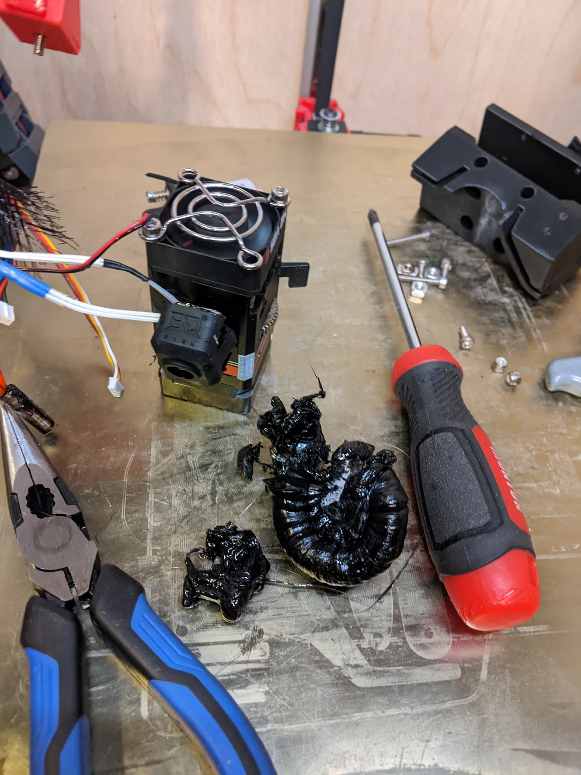
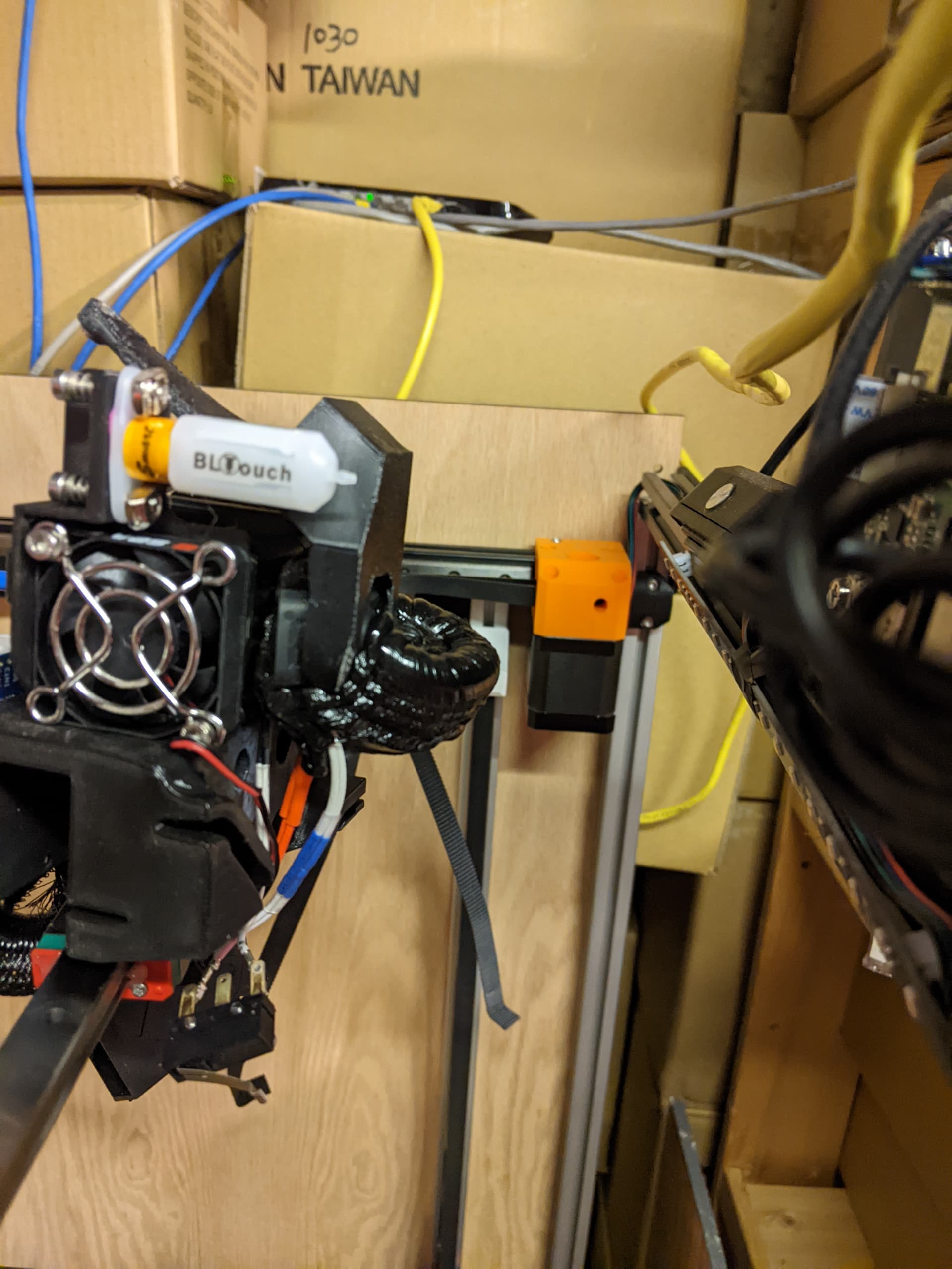
I’m pretty sure my board is dead. But i do have 3 spare SKR Pro’s here now since I changed all the CNCs over to Jackpot. And I also have an Octopus here as well. So idk which way I will end up going. I know I defiantly want to go CAN and get rid of this mess of wires going to the hot end. So it may just be time for a full revamp lol. This hot end issue has me all sorts of flustered but Ill make another post in my build thread about that.
Initial CAN setup was a PITA, but has been great since. Nice having the printer zipping around without dragging around a massive cable bundle. My printer.cfg was initially based on @probrwr’s and other peoples’ is on github here.
Note, I still haven’t bothered to setup accelerometer which, when enabled, may result in bandwidth limits being hit if my wiring was rubbish… Other than that, have documented and shared all my steps to setup CAN bus. You can watch 1x to 200x plus speeds at…
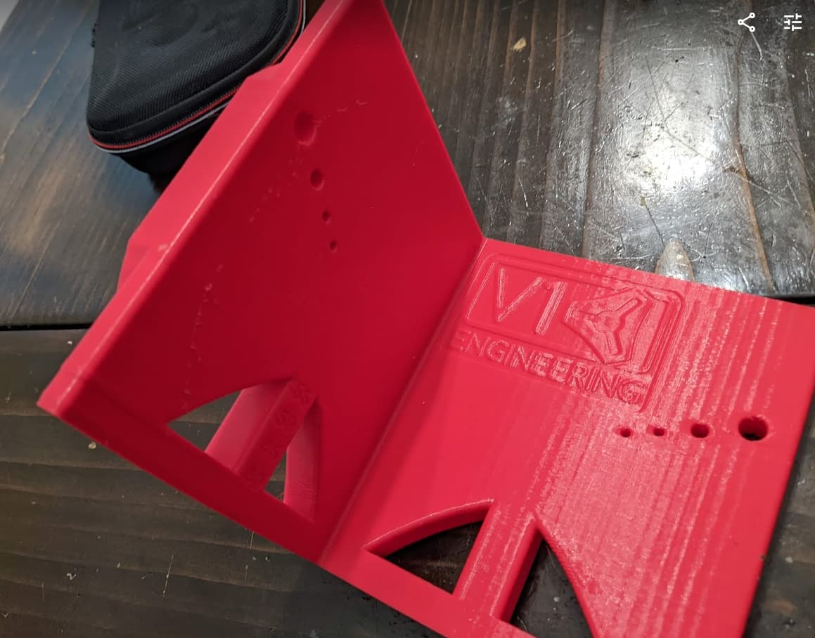
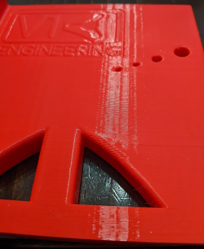
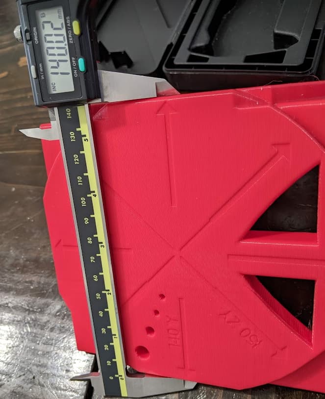
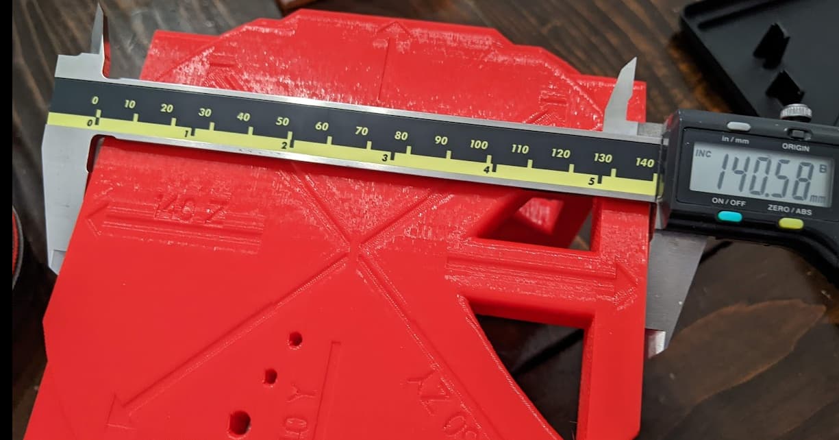
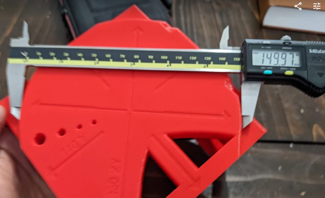
Some consistent bumps on the ZY face inside and outside. Maybe need to clean/lube the bearings or do something different with the wires to the hot end?
Is this good enough to print trucks? I’m seriously at the edge of my understanding on this. the ringing could be a resonant vibration thing, but the repeating wall texture is not. the Y measurements are good, but the X are off a little and there might be some little bit of over extrusion. The base layer may be too thick. Not sure where to go from here. Thanks for any input or suggestions.
Yeah, I would guess nasty bearing. Lube it loosen and check all four of the bearing block screws. That is bad, make sure it rolls really smooth. It could be the infill, how many walls did you use? 3 and it should not show, 1 and it will show for sure.
accel tuning.
Happens with bridging, those are not super great though, maybe extruder temps or cooling fan.
For what? (Probably, might want to do a few more test prints first).
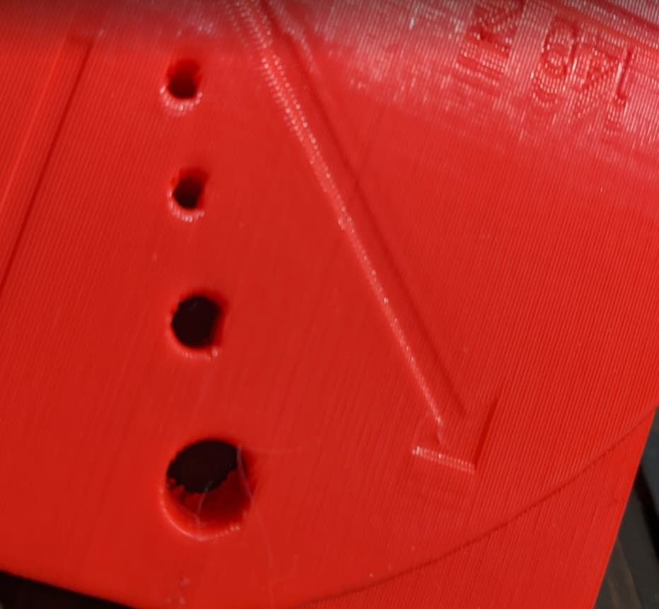
I’ve been working through teachingtech’s 3d printing tuning exercises. I am fairly confident I have the bed at the right height. I printed the initial cube, then I proceeded to the extrusion multiplier test to figure out over vs under extrusion. It runs vase mode single wall and you measure the wall of the 5 sided cube to see if the multiplier needs to change. The walls were shiny and actually pretty good until they all the sudden weren’t. Now there are holes in the wall like the extruder is skipping. I did discover that the hot end fan wire had come loose, so the fan wasn’t consistent. I replaced the last few dupont connectors with JST and everything is popped into place, but it still isnt’ printing right… see here:
I would skip that one, and come back to it later if you really what to. I have never done that test. You kind of have to do all the tests twice anyway. Get your printer close, then dial it in.
Make sure your extruder gears are not all full of filament and no longer gripping.
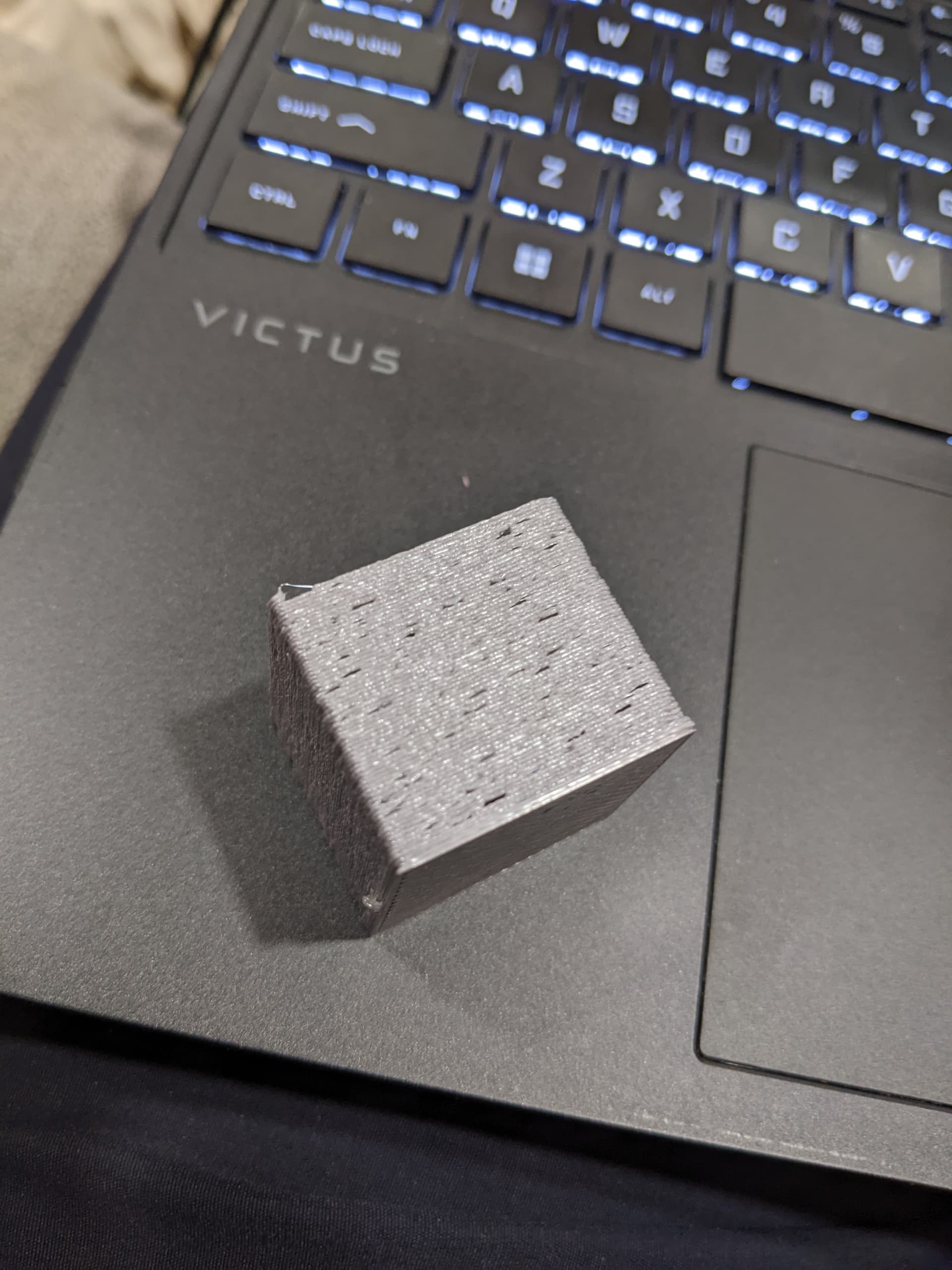
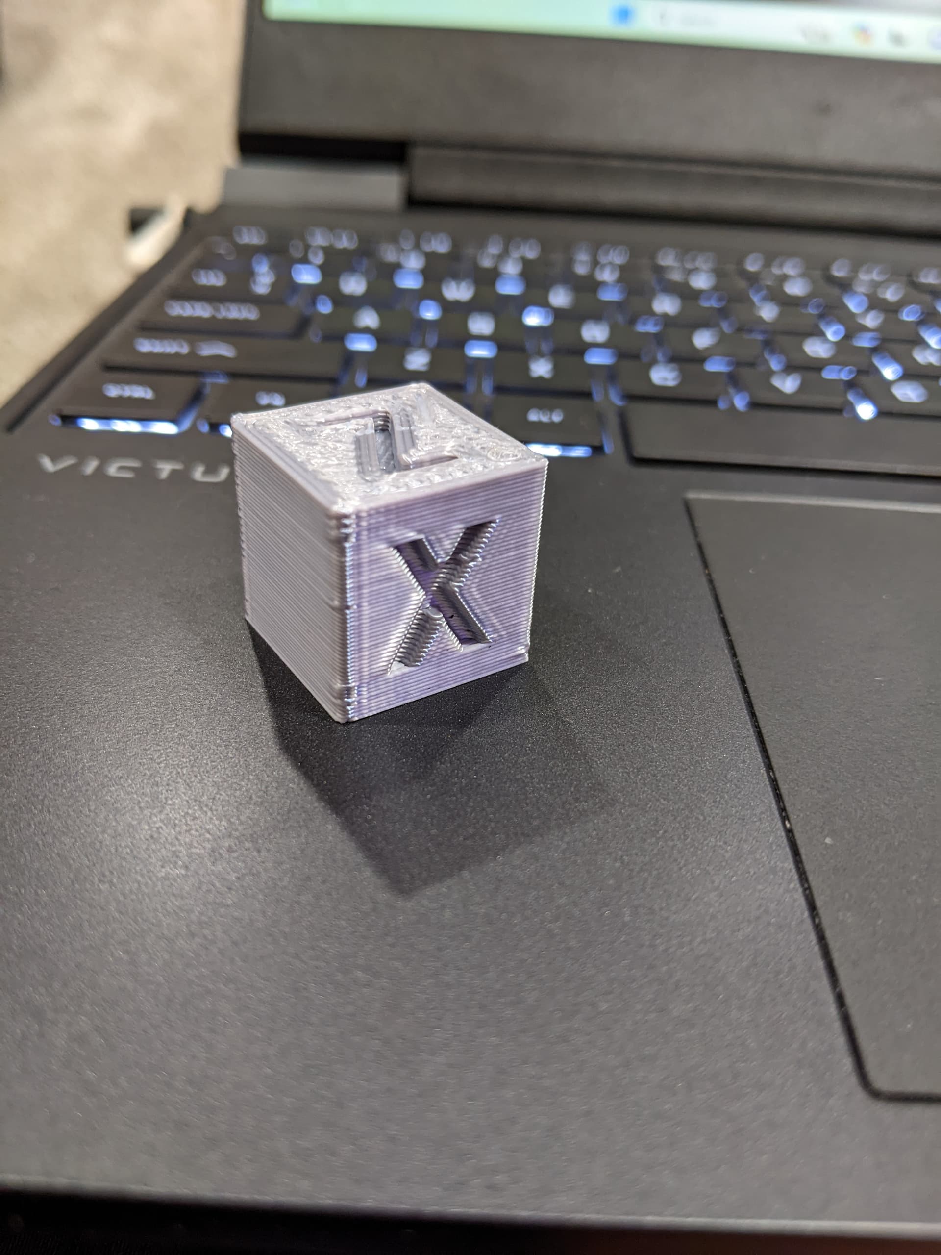
yes I believe that was the case, but I think it was my wire loom not being properly terminated at the extruder and some of the “hairs” getting caught in the extruder. I trimmed all that back and I just printed the cube that you print before the extrusion multiplier test and it looks like this:
The top of the cube is still not flat and nice, but it is worlds better than before.
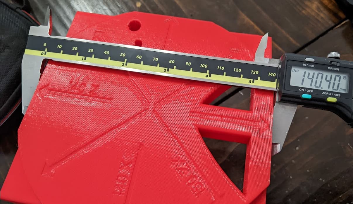
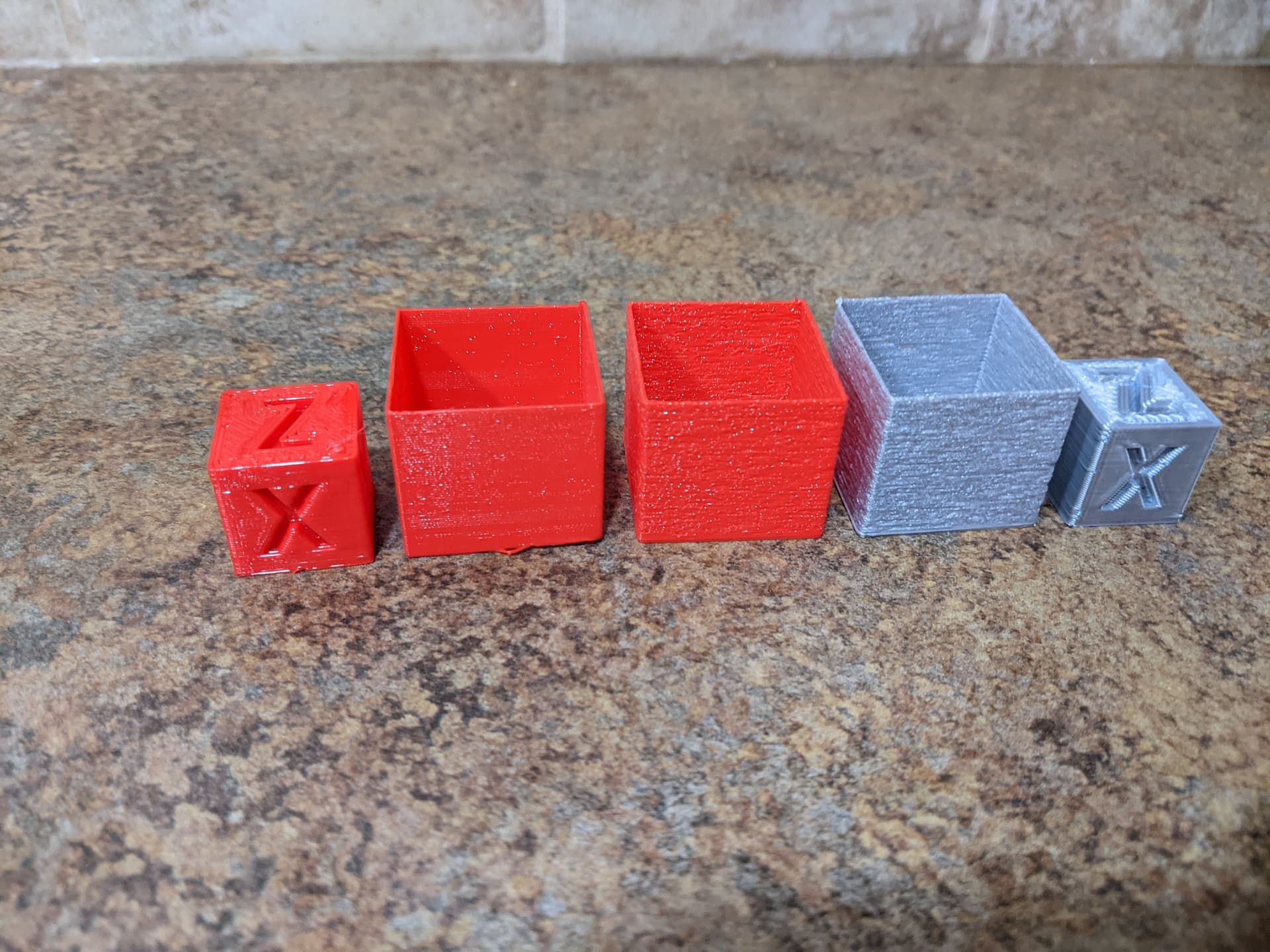
I printed a series of these single wall structures and then when it started skipping, I backed up to where they were nice and reprinted a couple of the earlier gocde files and it looked terrible as well, so something not likely gcode related changed.
the progression in pictures. there are many not shown in here.
oh! I’ve been contemplating printing cooling fan mount like yours to do an apples-to-apples comparison. The duct you’re currently using has shorter more direct air flow path than mine, I can’t tell how big the vent openings are though. Got link to the model you’re currently using?
Duct vents might be too low. Bottom of duct is ~1mm above bottom of Nozzle. During fast prints, noticed vents were either flattening (nice…) or pulling up (oh dear…) insufficiently cooled filament that was curling-up during benchy print…
Duct vents could be bigger.
Already tempted to rework for larger fan, or 2x 5015s.
Am no mech engineer, and haven’t done any fluid dynamics or formal analysis.
If anyone wants to tinker with this more, ping me and I’ll export and share a Fusion .f3d file containing snapshot of latest model somewhere.