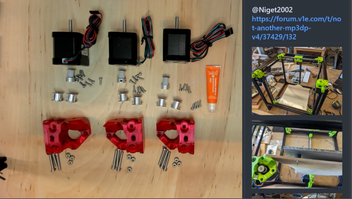
Assembling Z Posts/Trucks
Thanks to info from misc MP3DP builders.
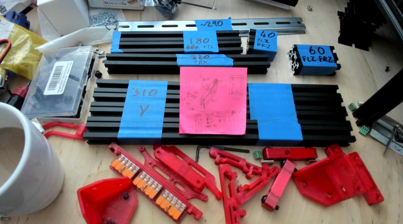
Parts :
- 24 x M3x10mm
- 3 x 4 per Z Post to Linear Rail Carriage
- 3 x 4 per Z Post to Stepper
- 9 x M5x30mm
- 9 x M5 nyloc nuts
- 6 x smooth Idlers
- 3 x 16T Pulleys
Thanks to info from misc MP3DP builders.
Parts :
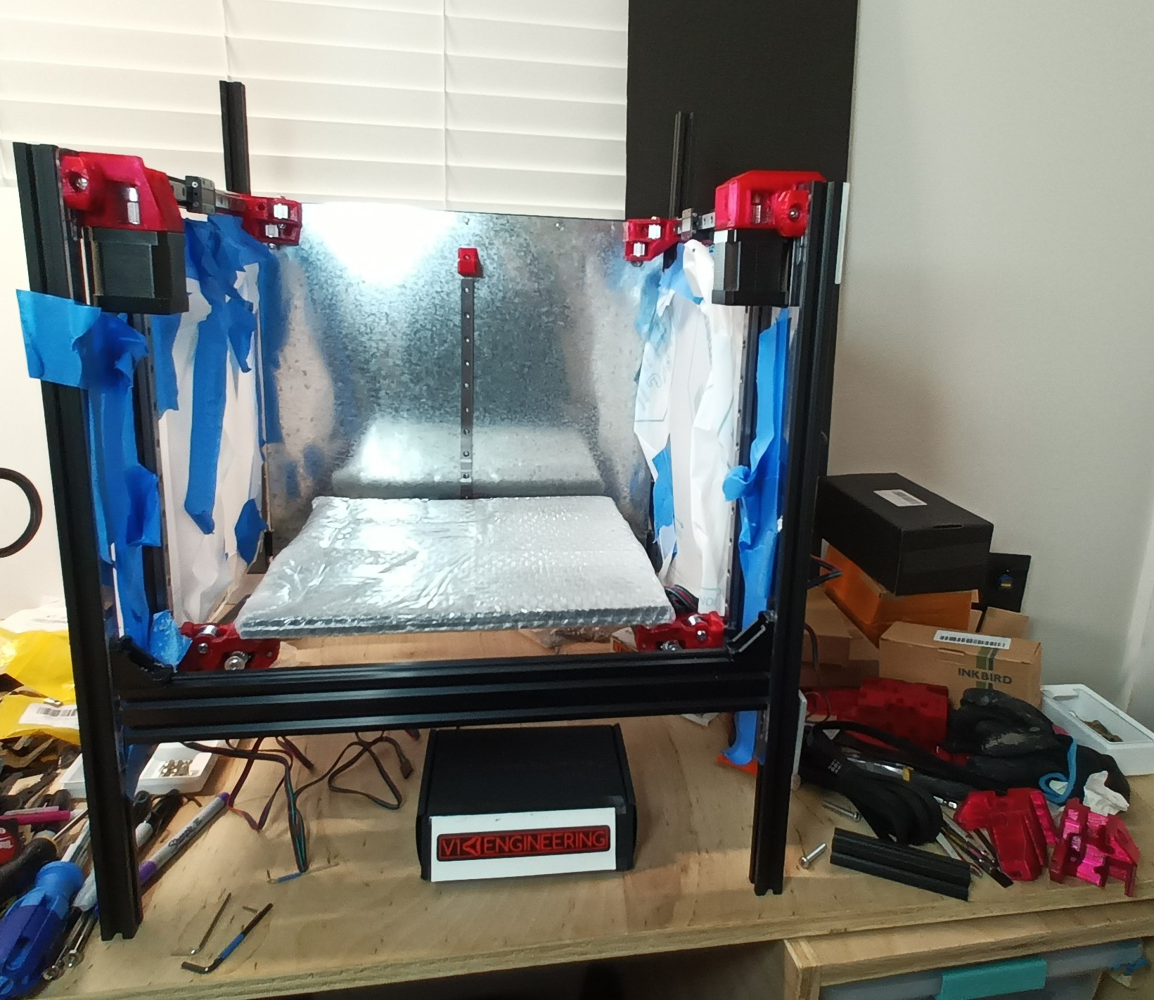
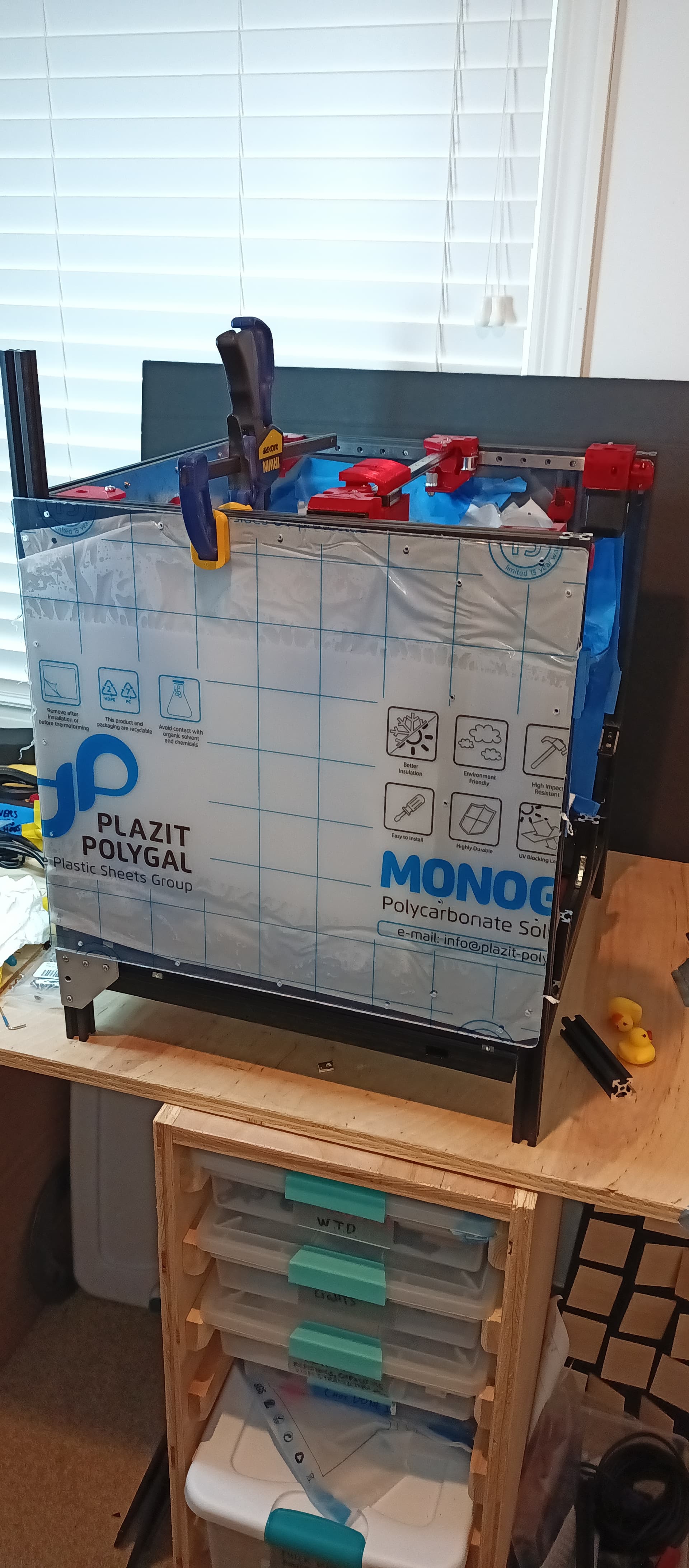
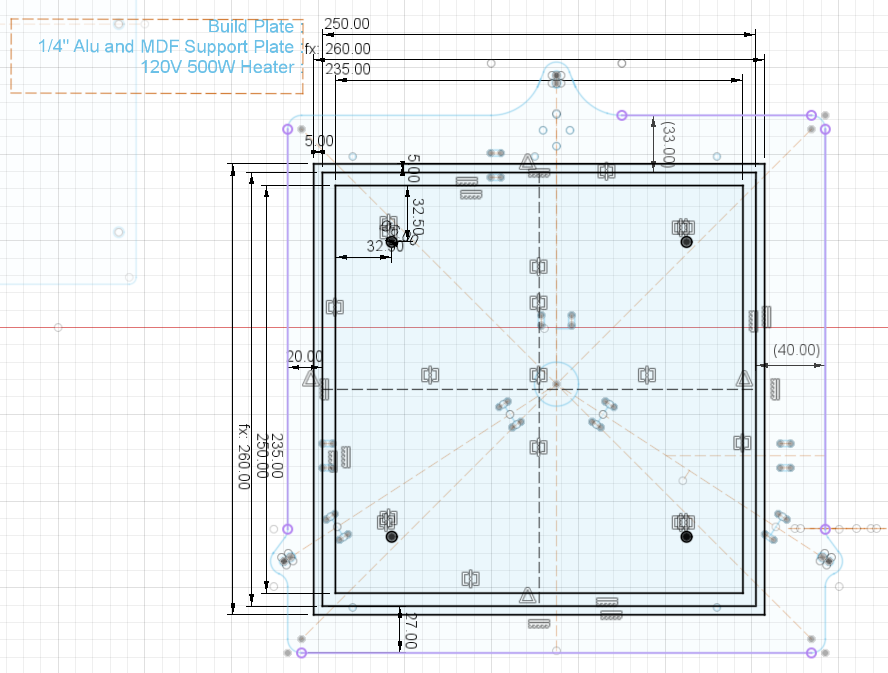
Built Frame for 250x250, but 12"x12" plate might physically fit. Hotend won’t be able to fully reach entire bed. I still need to confirm wiring will still fit if plate oversized for the frame is used.
The excess Alu bed will have unnecessary unused bed area increasing weight, and sink heat from usable area that actually needs heat.
Even so, for the sake of getting end to end functionality working, will live with the excess weight/heatloss for now since it’ll avoid me having to cut Alu bed smaller in the short term.
Thinking :
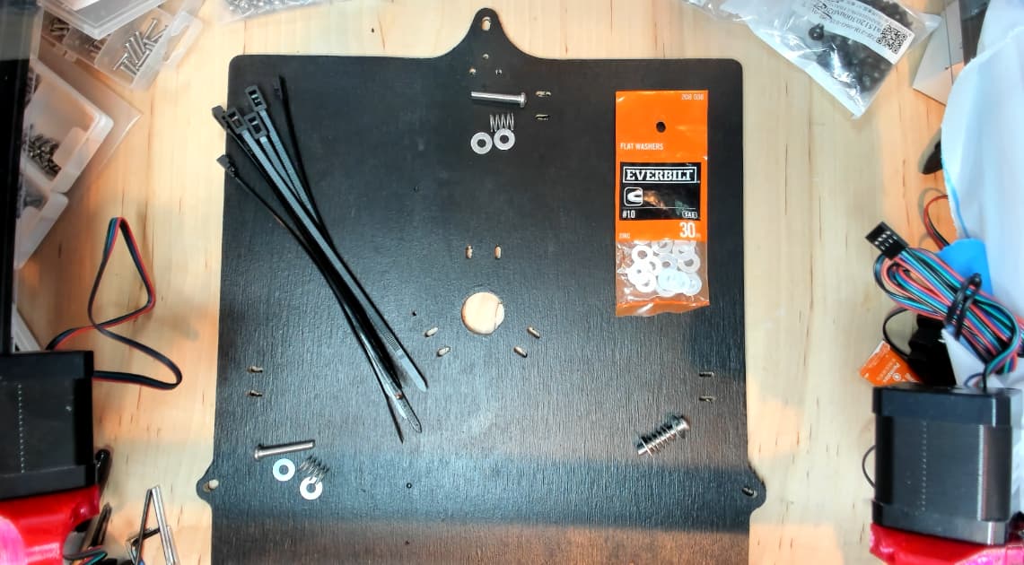
Parts :
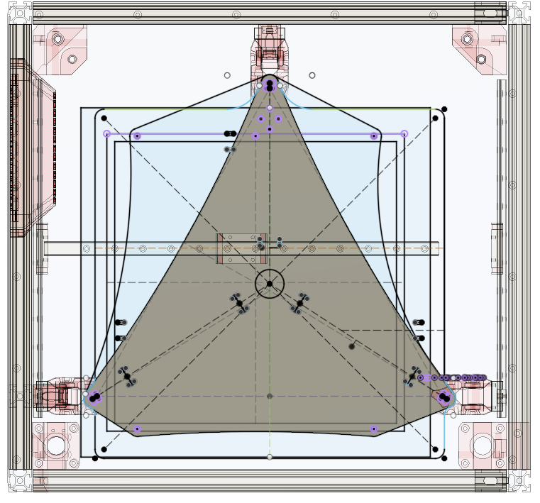
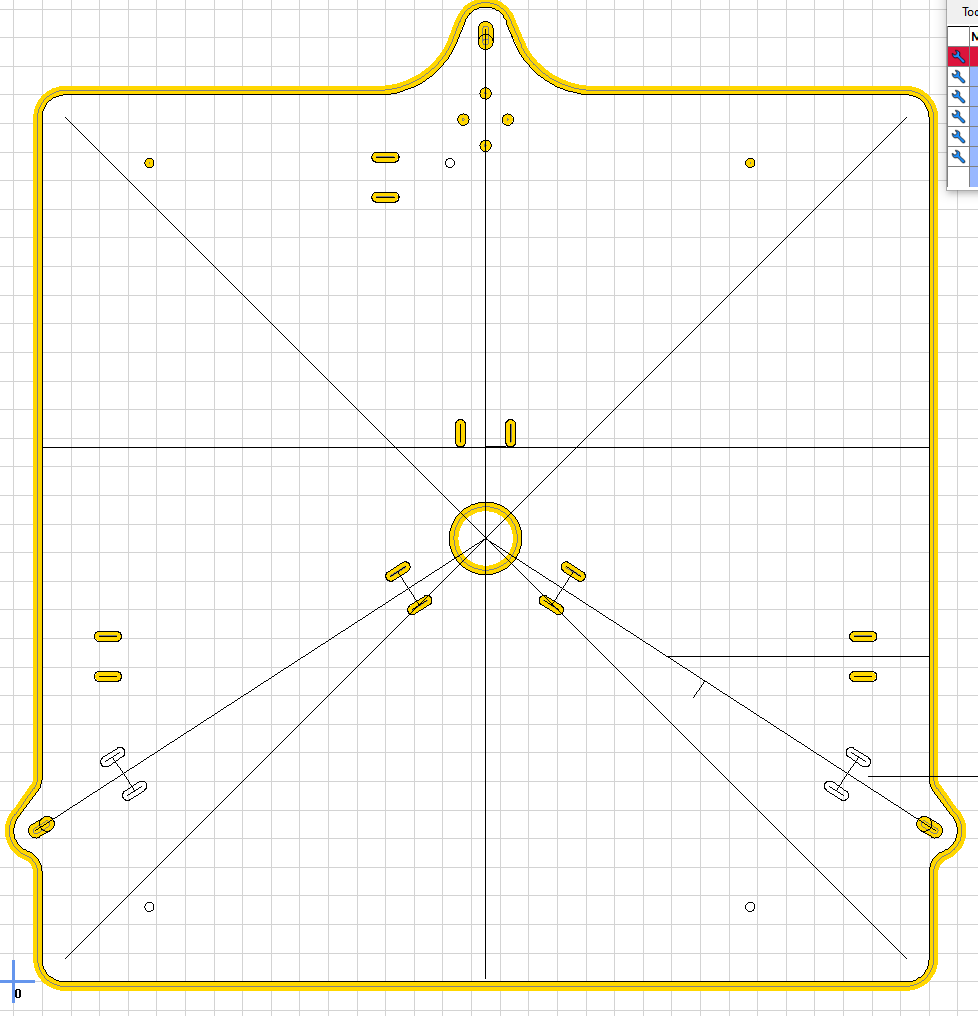
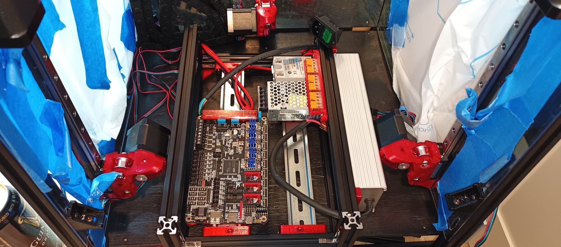
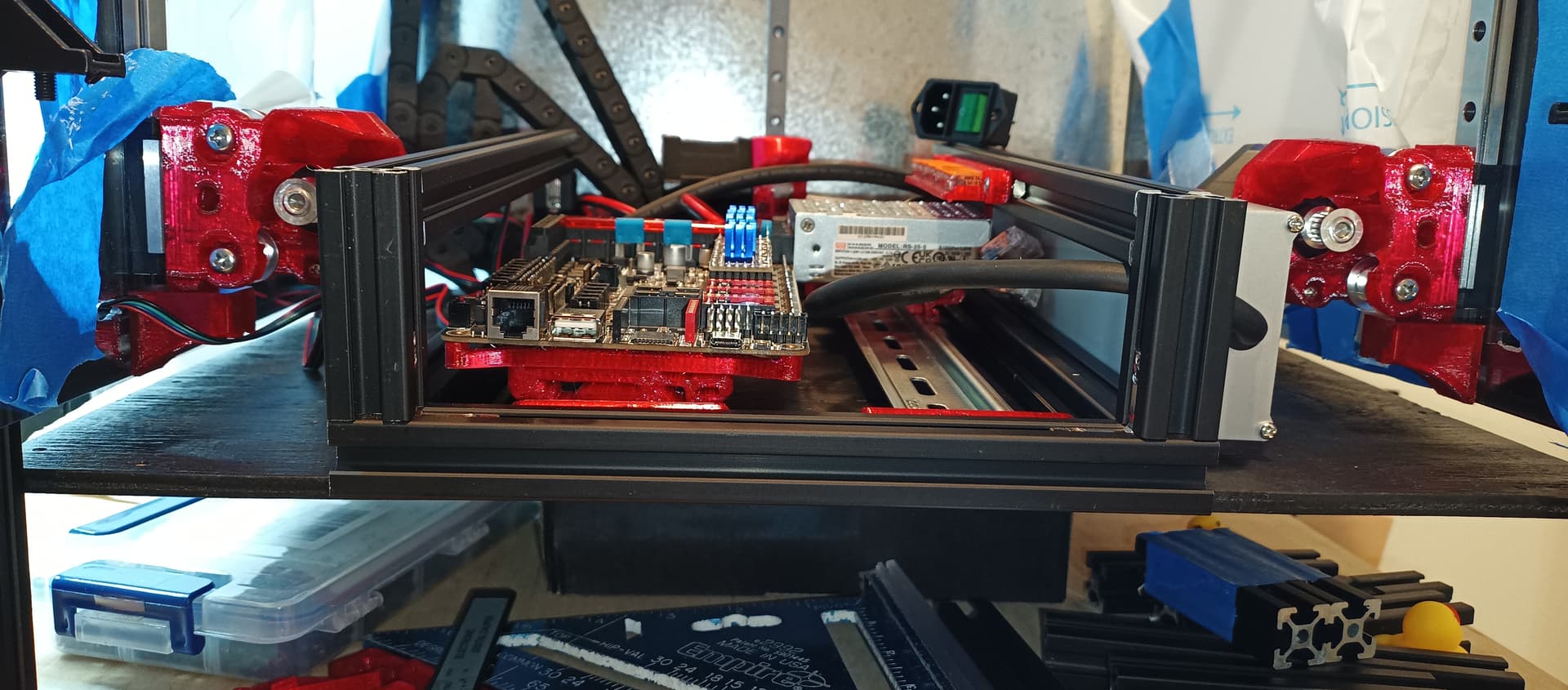
Was tempted to reduce overall wiring length required by dropping through center of Bed Support Plate, with controller underneath the printer. Would need to figure out wiring protection, strain relief, maybe the zip ties would be enough? Decided to drop wiring out back of the plate. Hopefully route wiring within a drag chain…
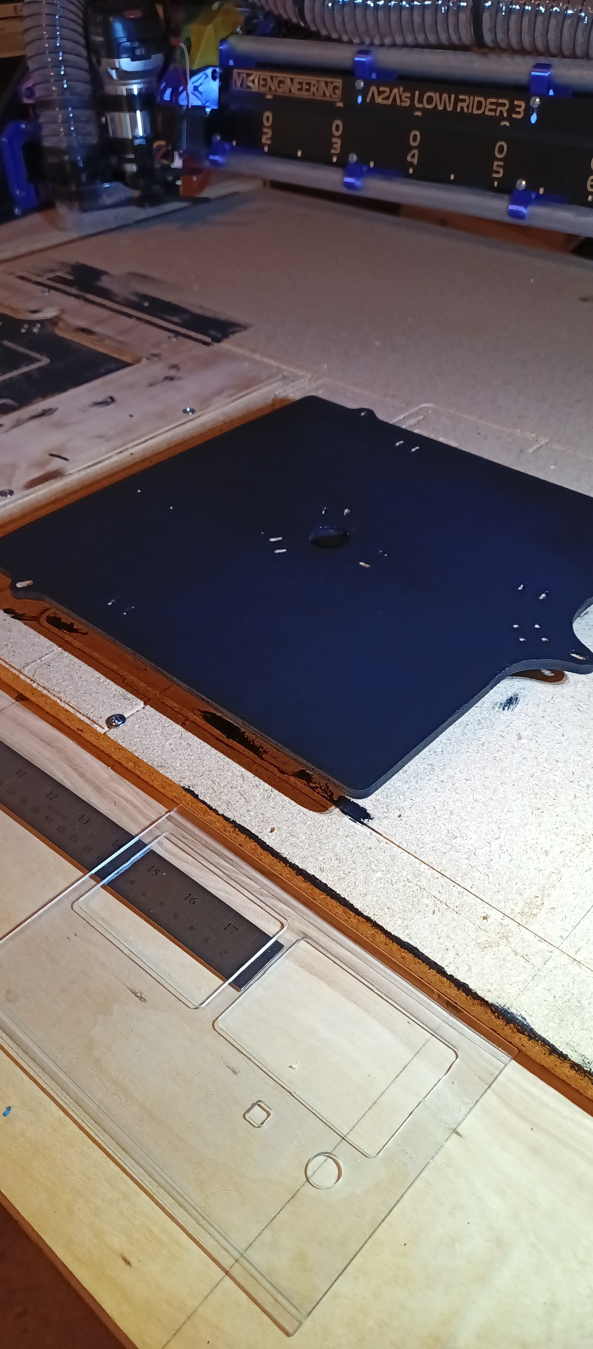
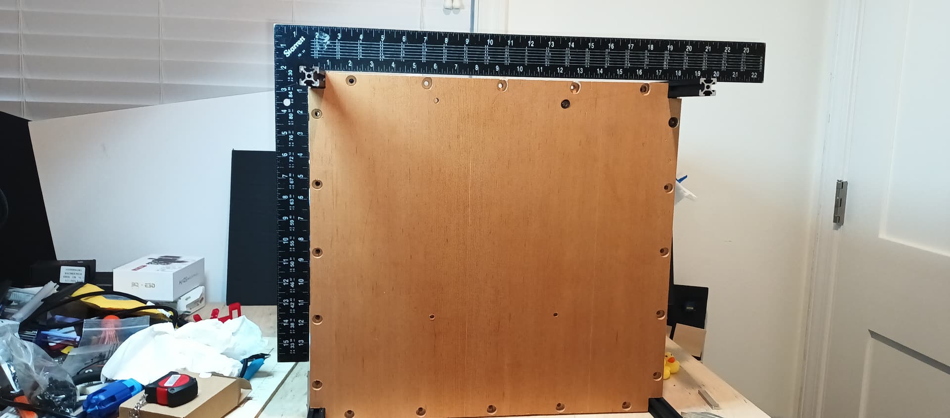
Note holes for bed are missing. Reason is I don’t know where it’s going, waiting until hotend is assembled and I have better idea of usable XY that nozzle can reach.
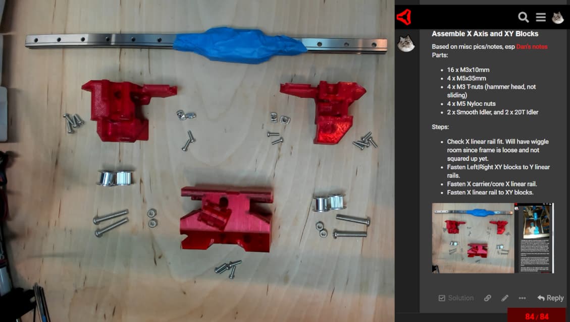
Based on misc pics/notes, esp Dan’s notes.
Parts:
Steps:
This is what i did. I will post a picture on my thread this evening when i get home.
Decided to ensure am not ready til the last minute, by not scavenging my dual screen LR3 case as-is. My LR3 case would fit, but it’s too chonky, doesn’t look good. Going to burn time modding this mod and attempt to make something slimmer, will shove Octopus and everything else further back under the bed area into the extrusion/sheet-metal portion of the case.
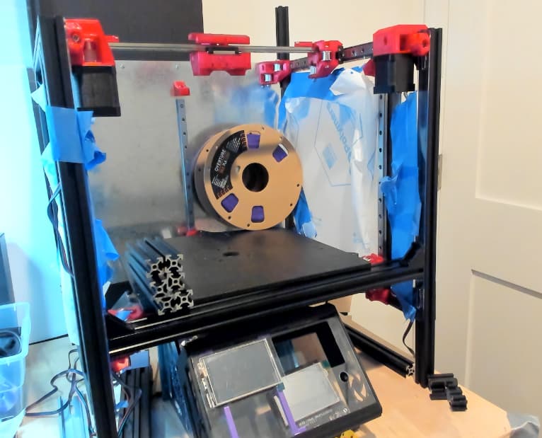
Spool won’t fit in the back right corner as built for 250 Usable X, adding an extra 25mm would have worked. One option, without rebuilding would be to cut an opening into the interior panel. Leaving as-is for now, focused on getting wiring working…
The right side should have more room then the back or left. The bed is shifted a bit.
Sheet metal enclosure box would be ideal, but I figure an extrusion one will be easier to assemble/tweak/mod…
Planning Power switch at the back of the electronics enclosure, somehow.
Bottom panel is temporary, it’s actually the back panel. Cutting bottom panel now that enclosure dimensions are known.
I am routing my on/off switch to the front panel. I don’t like having to reach around machines to turn them on.
Honestly, I usually have my 3d printer on a smart switch and use that to turn it on remotely, so I may never use the physical switch. I might need to rethink this.
Interesting, could add front switch as well, probably soon… One benefit of putting the switch behind the electronics enclosure is that my arm/hand will dampen the fall of the hot bed.
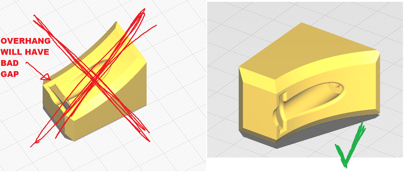
Belts not fitting easily, because I used wrong print orientation for Z Belt Holder. I should have read Repeat v2 topic more thoroughly, e.g.
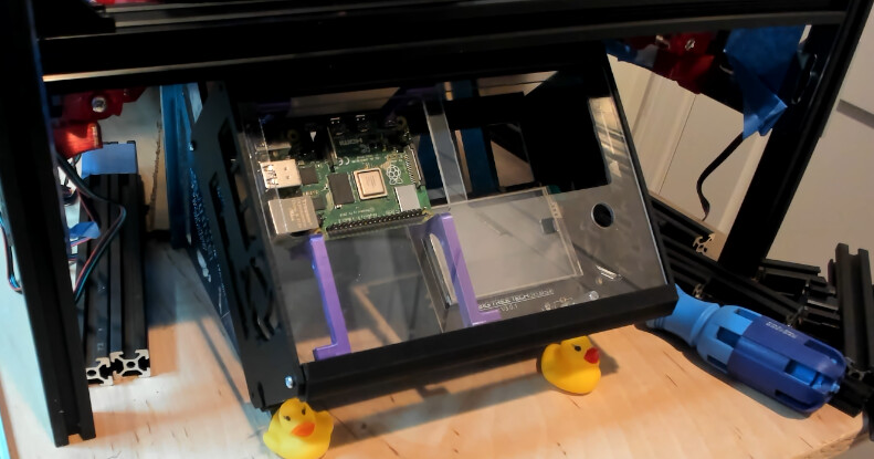
Anyone already running Marlin on Octopus, within their MP3DP v4 ? Will try out Klipper, but not this week.
Found snapshot of V1E MP3DP v4 flavor of Marlin 2.1.1 515 source code. Downloaded/copied from Marlin Firmware - V1 Engineering Documentation
That firmware and source code Snapshot in initial commit was compiled for SKR Pro 1.2. Planning to submit edits in this repo to build on Octopus v1.1. Will diff and integrate V1E 515 Marlin edits to support Octopus used within my LR3.
Cheers!
Stick with that release of the firmware for all your edits, right now the nighties are all messed up with bed leveling right now, for the past month or two. The Marlin team almost has it fixed.
Anyone using relief cuts in their bottom panel? Accident sparked an idea… Thoughts?

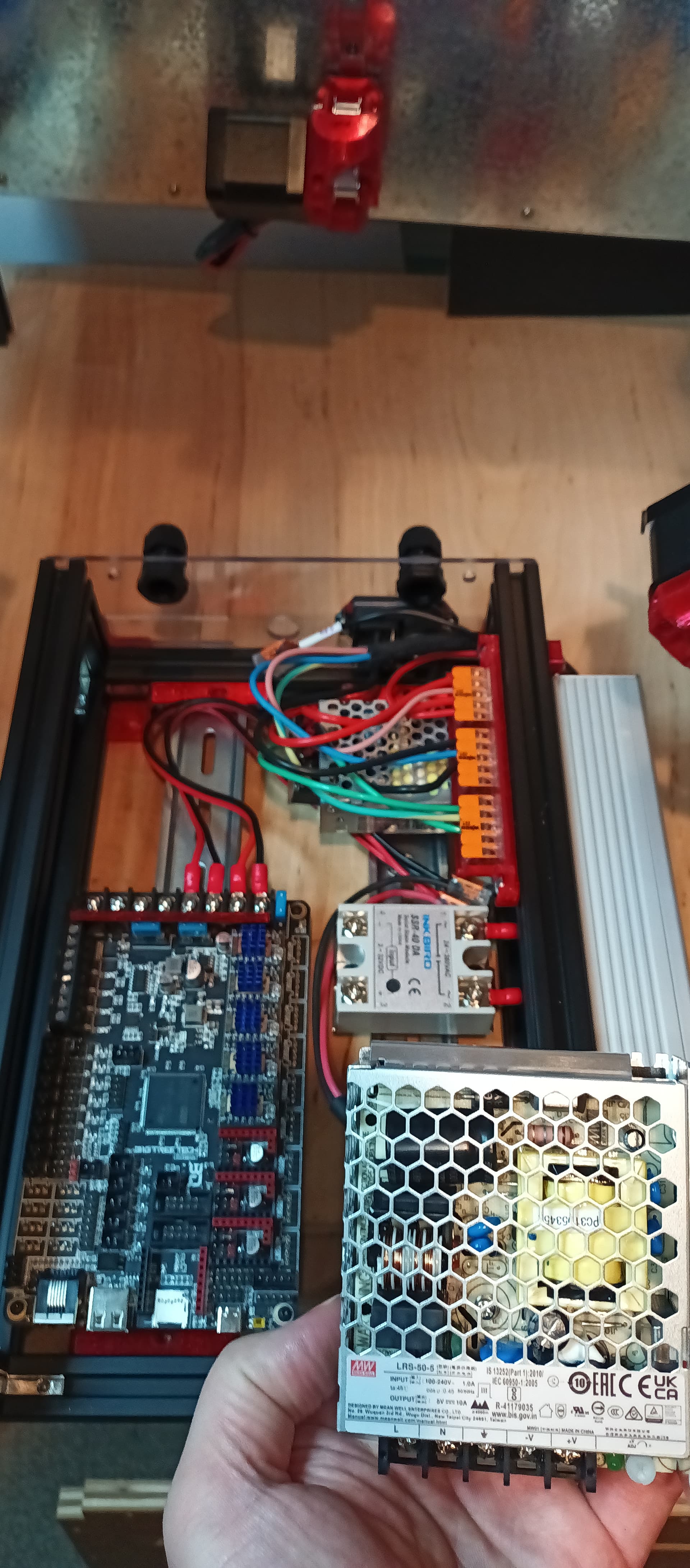
Using LRS-50-5 instead of LRS-25-5 if I can make it fit.
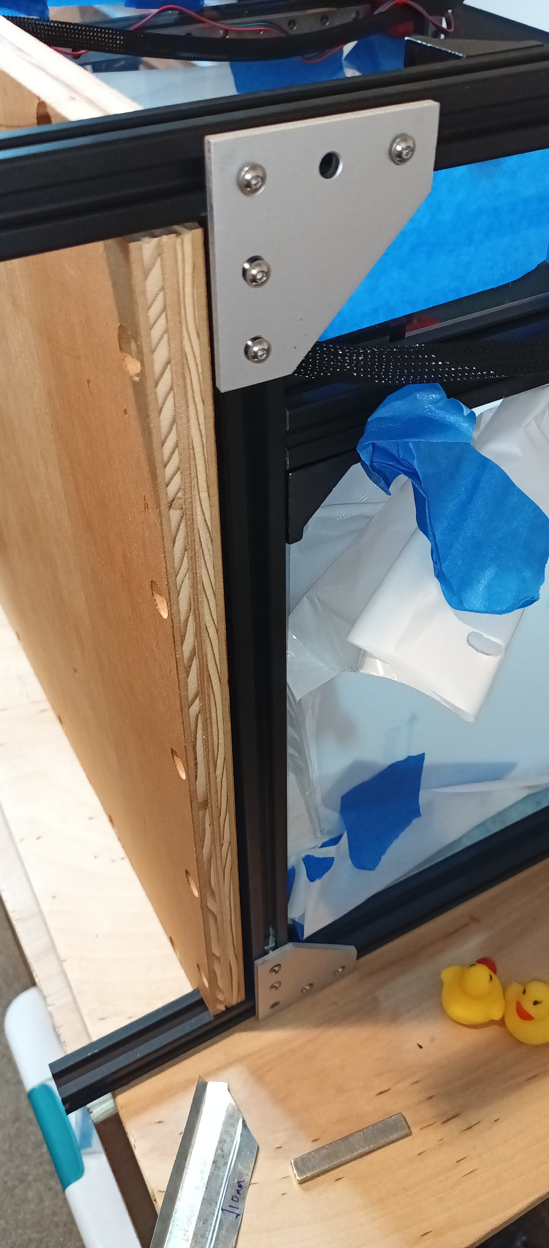
Internal panels secured. Currently test fitting external panels, will peel and fasten properly at RMRRF
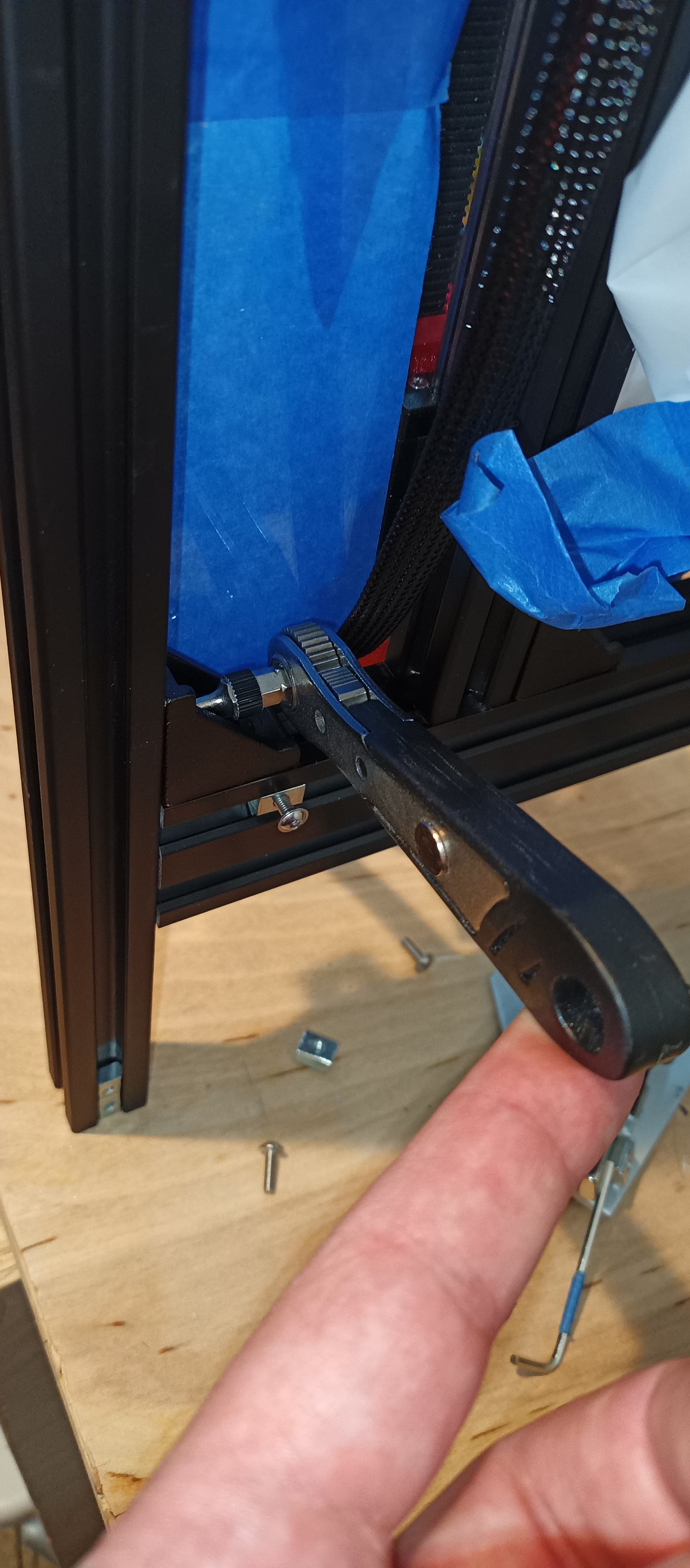
For your sanity’s sake, consider a micro rachet wrench…
To attach Alu plate to bed support plate, am using the leveling bolts, springs and adjustment wheels that Ryan kindly sent me.
Good to spend some time at RMRRF looking over your printer build.
You’d have made more progress at the show if I hadn’t talked your ears off for hours.
Thanks again for your time.
@MakerJim was great meeting you, and other current, and future V1E crew today. Always a pleasure talking to rocket scientists and engineers. Your 3 planet slingshot to visit deep space asteroid on a respectable/unbelievable budget is a fascinating project. I respect anyone who can simulate the universe ![]() . For me, meeting up and talking to you guys was way more important than progressing my build. Cheers!
. For me, meeting up and talking to you guys was way more important than progressing my build. Cheers!
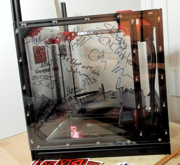
Looking to finish this build and actually get it to print something. Honestly though, am quite happy just looking at it in it’s unfinished tagged state.
Love that the tags left by V1E legends and YouTubers were made by folks that have left a mark on me. They’ve guided me to be able to print, cnc, build and more. e.g printed my first 3D part (a cat toy…) while watching one of Zack Freedman’s streams.
Currently figuring out how to best preserve the sharpie tags from people met at RMRRF. Any suggestions? Clear vinyl maybe? Or, move exterior left panel to be exterior right panel. That way, the tags on the left panel’s exterior will end up in the air gap chamber. Readable when looking from inside the chamber. Reversed from the outside. Thinking about it, this approach will look awesome if I get a bed cam and lighting setup correctly.
I would use it as an inner panel, but I would have it so that the ink is between the inner and outer panel and is visible from the outside. I’d also put some smoked or white vinyl on the other side of the panel to help make the sharpie stand out. Maybe put some LEDs on the extrusion between the panels to light it up. Put a clear panel on the outside of that wall so that you look through the outer panel to see the names on the inner panel.
This would keep the ink between two panels so you don’t accidentally touch it. It might also help any heat from inside the printer from affecting anything (although it shouldn’t)
I would not try to put any vinyl over the ink itself. Any screw ups and it would lift the ink off the panel.
A quick google shows that acrylic paint should stick to acrylic sheet. You could try spraying some clear gloss acrylic over the sharpie to protect it. I’d recommend trying this on some scrap first.