That’s a great idea!
1 Like
@jono035 , @MakerJim, yep am looking to blob fix my limp CAN bus wiring…
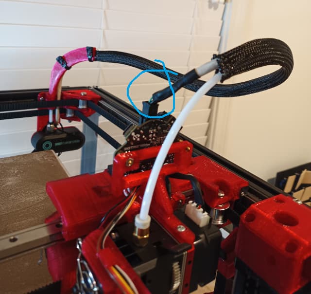
Took me far too long to model the PTFE guide in the background. Someone at OpenSauce.live taught me about the power of flexible materials. Planning to create a quick cone forming mold, and fill with silicone, or something else maybe? Cone shaped blob, e.g. ![]() with max rigidity near the connection.
with max rigidity near the connection.
1 Like
Oh, I see what you mean. I’d either just find a convenient nearby location to cable-tie the cable to, add a mechanical ‘stake’ to cable tie it to (often in other designs you’ll see little protuberances on PCBs or parts for cable retention like that) or cable tie it to the bowden tube to provide some stability.
If you’re specifically looking to mechanically reinforce that joint, a short length of glue-filled heat shrink would do that nicely, as would likely just regular heat-shrink over the top, although with a lot more flex to it.
3 Likes
Or rubberweld tape!
2 Likes
I’ve not used it in that way before but yeah, that’d probably work nicely.
Cheers for the suggestions, was leaning towards remixing…

But found something similar to rubber weld and ended up with…
For now…
5 Likes
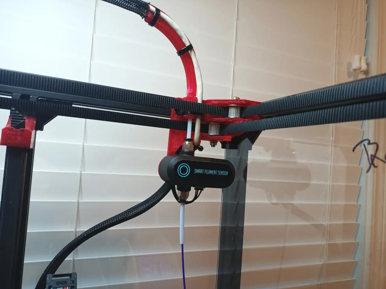
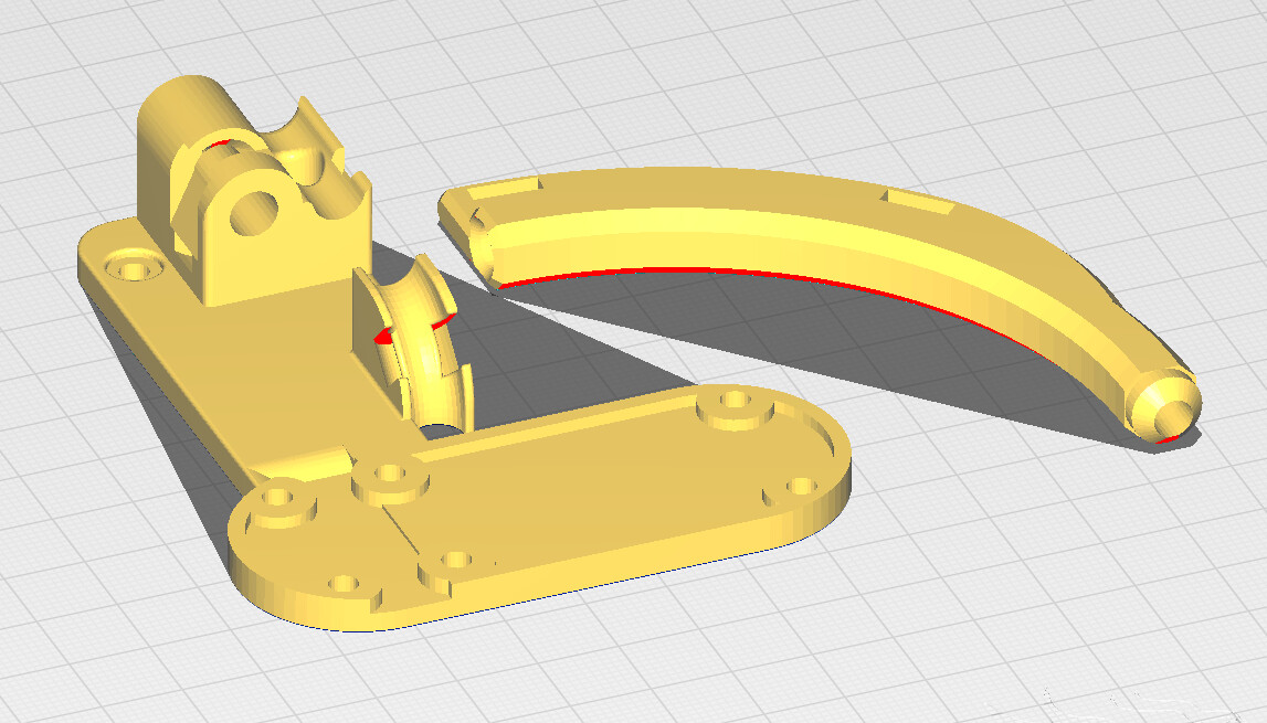
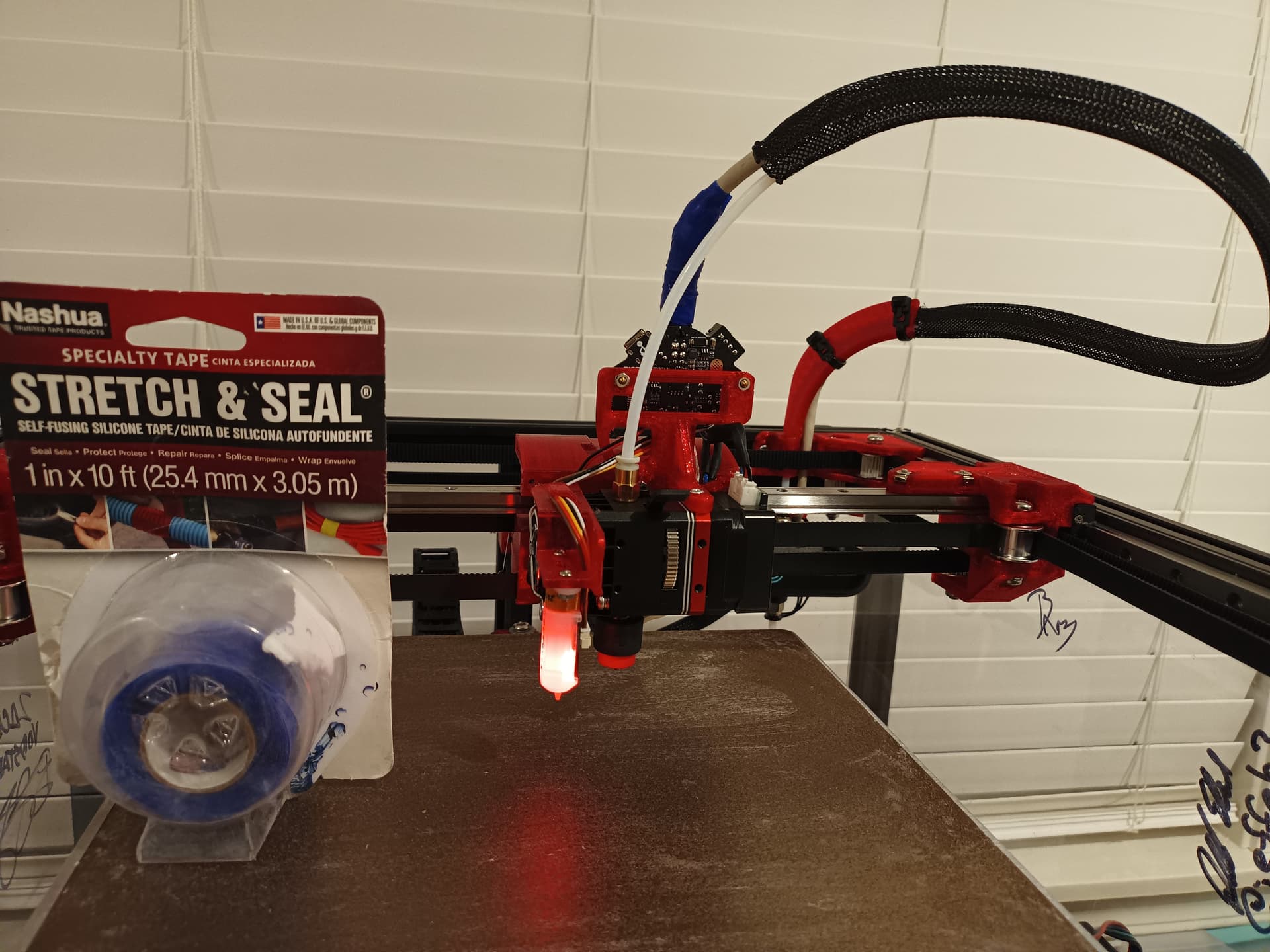
Assembly, mount guide for PTFE, CAN Wiring and BigTreeTech Smart Filament Sensor (BTT SFS v1.0)
Created compact tidy enclosable guide for PTFE, CAN Wiring and BTT SFS v1.0 sensor. BTT SFS can detect runout, jambs and flow issues. The PTFE Guide ideas breakout topic has design discussion details with various forum folks.
Parts
- BTT - Smart Filament Sensor module
- 2 x M3x8mm button head bolts
- 2 x M3 sliding/roll-in nuts
- 4 x zipties
- 3mm ID X 4mm OD PTFE - Note large inside diameter, less filament friction, less PTFE drag, more flexible, but easier to kink. Could be an issue for brittle filaments, we’ll see…
- Print parts at Printables or GitHub.
Klipper Config Changes
- Added [filament_motion_sensor SFS_T0] section to my printer.cfg.
Related
- Voron Docs > Setup a BTT Smart Filament Sensor
- Teaching Tech - BTT Smart filament sensor guide - Detect filament runout and jams
- BTT Smart Filament Sensor - 2022 - Chris’s Basement
- Klipper Docs > Config > filament_motion_sensor, note sensor detects motion, is NOT switch based.
- BTT - Smart Filament Sensor module - User Manual.pdf
- Read instructions, including “VI. Wiring Method” which shows pinout for Voltage, Signal, Ground. Pay attention since board doesn’t have reverse voltage protection
 .
.
- Read instructions, including “VI. Wiring Method” which shows pinout for Voltage, Signal, Ground. Pay attention since board doesn’t have reverse voltage protection
- BTT - Smart Filament Sensor module - User Manual.pdf
- Klipper Docs > G Codes > Filament Switch Sensor
- Commands to enable|disable and query sensor state:
- QUERY_FILAMENT_SENSOR SENSOR=<sensor_name>
- SET_FILAMENT_SENSOR SENSOR=<sensor_name> ENABLE=[0|1]
- Commands to enable|disable and query sensor state:
- BTT Smart Filament Sensor - InDepth Review - Design Prototype Test
- “everything about this sensor is a disaster, complete waste of money”.
- BTT Smart Filament Sensor Electronics Discussion - Design Prototype Test
- “Unmitigated pile of feces”

- “Unmitigated pile of feces”
Troubleshooting / Questions
Question: Anyone know if removing filament should cause Klipper dashboard displayed value to transition from detected to empty? Am using BTT Smart Filament Sensor with Klipper, signal wired to Octopus v1.1, one of the endstop ports. Sensor tracks motion, isn’t just a switch. Posted same question to Klipper Forum too.
- Answer: gabe.mi helped me understand that BTT Smart Filament Sensor only detects motion, so when the Extruder is not actively moving, the sensor doesn’t have enough information to infer whether filament was inserted/removed. A separate switch based sensor would be needed.
5 Likes
Sorry I’m late to reply, but I think your wrap with a flexible tape is a big improvement.
I usually work with connectors that have backshells or boots to manage wire egress from the connectors into the harness bundle.
If you hadn’t done that wrap, that spot where the wires emerge from the connector on the CAN board in the area you circled in blue would likely have been a failure point and sooner than you’d like.
The bummer is that for moving harnesses it seems that anywhere there is a tie wrap, harness split, or other pinch point that just becomes the next spot where wire fatigue happens.
Your bundle looks MUCH better after wrapping it, and that curved strain relief also looks like an improvement.
I’m curious if that CAN board connector has some kind of boot or other wire management feature that should be used with it. Do you know what connector is being used?
I would keep an eye on the bundle and see if there are any pinch or pivot points that either bend the same spot more than the rest of the bundle, or which bind for a part of the travel and tug on the gantry.
One thing I’ve done in the past that might help was a bit of a lemons to lemonade story. I ordered some 2mm ID 4mm OD PTFE tubing for a remote bowden extruder setup. I turns out that whatever the foreign supplier shipped was 2mm ID, 3mm OD, and NOT PTFE- it was super flexible. It was almost like aquarium tubing. Crappy and completely unusable for a remote bowden extruder setup. But it was perfect for a filament run from a spool holder to a direct drive extruder. That setup only has to pull filament through which is exactly what your printer is doing. I used that material on my TAZ for a while until I ditched the side mounted spool and went with an overhead spool. It was a noticeable improvement on the TAZ.
At the local makerspace, there were a couple of members with hybercube printers that used a long rubber band setup tied well above the printer to just slightly keep the top of the loop suspended. Not enough tension to tug on the gantry, but rather just enough to keep the loop from drooping and getting pinched or jammed in the gantry. I was never sure if I liked that setup.
2 Likes
are those CAN board connectors MOLEX micro-fit 3.0 connectors?
I see there’s a strain relief clip available but don’t see any boots or other cable management accessories.
Your wrap, or a shrink tube equivalent, looks like the best available option.
1 Like
Thank you for the info and suggestions @MakerJim!
Not seeing any wire management feature on the EBB36 board. You’re right the connector is Molex Micro-fit 3.0mm pitch. datasheet.
Nice, am checking out Molex Backshells and Boots. For some reason, not stumbled onto backshells/boots for micro-fit 3.0mm pitch. However, am seeing backshells/boots for mini-fit 4.2mm and larger connectors. ![]() , no prob, am happy with the wrap for now… Good to know about backshells/boots, will use for future projects.
, no prob, am happy with the wrap for now… Good to know about backshells/boots, will use for future projects.
Using the wrap is just a temporary solution to buy time until if/when more compact carrier optimized for BIQU is available. Mike, Ryan and maybe others (?) seem to be tinkering with the Carrier…
Would be nice to see a carrier that aligns CAN wiring as close as possible to the PTFE so they can be strain relief together and curved ~90deg (similar to the PTFE guide at the back of my printer). One of my goals is to minimize lid height.
@azab2c How are you liking that filament sensor? I bought one to put on my V4 but haven’t gotten around to messing with it yet. Dealing with the firmware side still has me a bit intimated. I know you are running Klipper so that wont be the same as me running the V1 Marlin.
2 Likes
No opinion yet, configured sensor in Klipper ( [filament_motion_sensor …] ), but still haven’t gotten around to properly trying out beyond some basic tests. Will provide an update after getting some real usage.
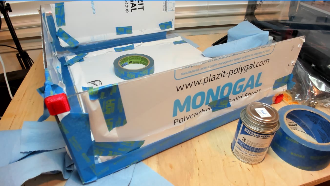
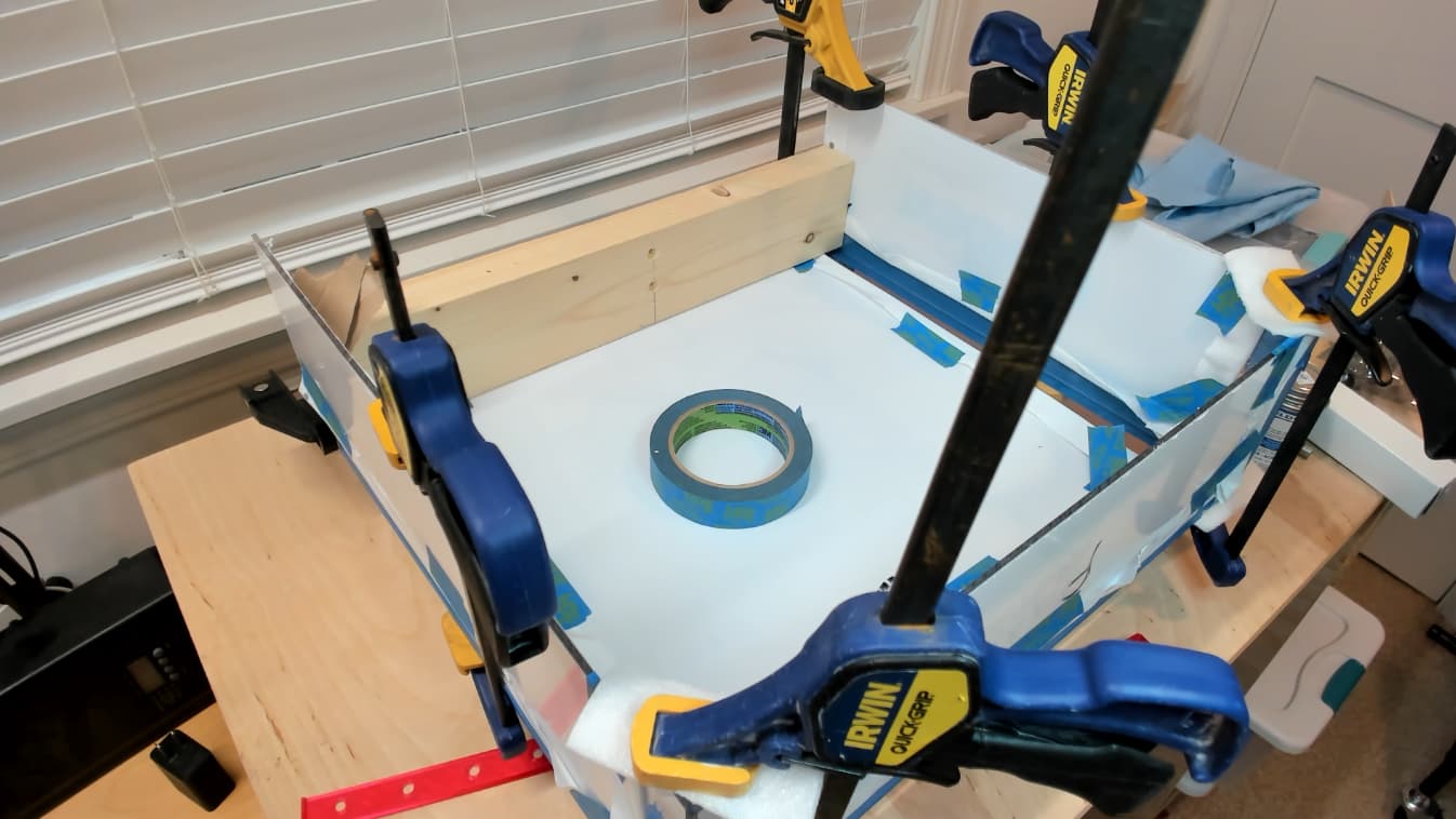
Currently learning to solvent weld polycarbonate…
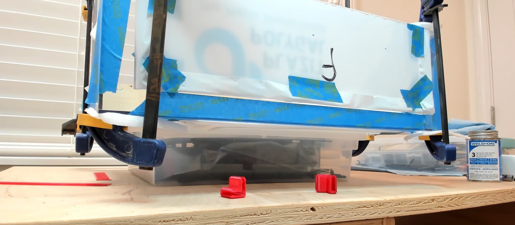
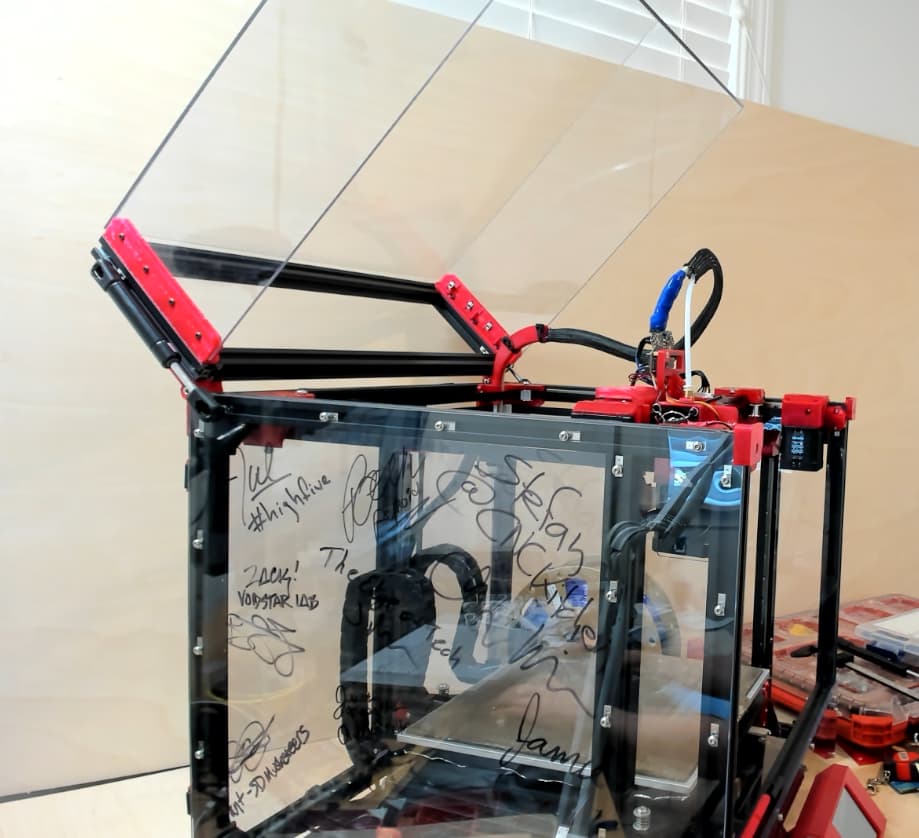
Assembly, Lid, Mostly Polycarbonate
20N 4.4lb Gas Struts still feel too powerful. Weaker 10N 2.2lb Gas Strut or Gas Damper would probably be better ![]() , McMaster Carr are $$$, am still figuring out place to buy… Regular gas struts only seem to be rated up to 50C, so may externally mount depending what high temp failure (
, McMaster Carr are $$$, am still figuring out place to buy… Regular gas struts only seem to be rated up to 50C, so may externally mount depending what high temp failure (![]() ?) looks like…
?) looks like…
Lid height is 145mm, bit taller than I’d like. Back is open currently, am waiting 24hr+ to cure ~80% full strength before attaching struts, hinges, and eventually filter/fans. Will be using like this for a while, at least until if/when compact carrier and hot-end PTFE guide are available. Lid could do with handle/pull, I should’ve cut holes for handle before solvent welding.
Edit: Spoiler… Turns out that 20N 4.4lbs Struts were too weak. Ended up with 30N. Details in later posts.
7 Likes
I keep picturing that printer warming up and the lid popping open mid print like an angry pacman…
2 Likes
My favorite style of backshell had two grooves in it where a circular memory spring clip could be installed. The inner (closest to connector) spring clip would capture and secure the outer covering (like the black snakeskin on your harness).and the outer spring clip would capture and secure, and electrically connect an EMI overbraid that lived inside the outer covering.
These were mechanically rugged, easy to install, easy to remove, and could survive being launched into space. They weren’t cheap. But I keep thinking that a 3D printed variant of that would be interesting for 3d printer applications.
Edited to correct which part went where in the backshell to harness retention.
2 Likes
23-08-06 EDIT: Ended up creating and using a better hinge with 90 degree stop ( Printables and GitHub ). Left this here incase someone wants 180 rotating hinge. Details about newer hinge in more recent post.
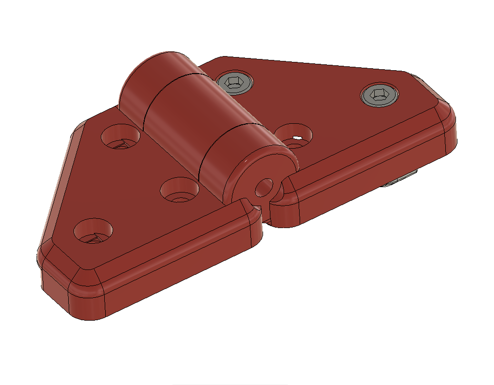
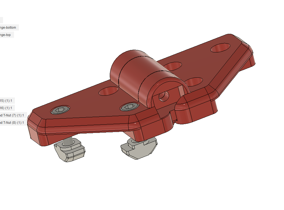
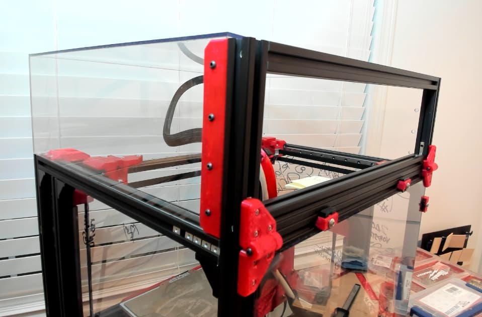
Assembly, panel corner clip hinge
Was looking for 2020 hinges that can also hold/protect 1/8" (3mm) panels attached to both the top lid panel, and bottom back panel. Hinges need to support Lid weight, and resist twisting/shear forces from the Gas Struts. Struts are currently 20N 4.4lb, still looking for 10N 2.2lb … 3D printed damper would be nice.
Looked at various designs, ended up forking a Voron Trident 2020 corner panel clip 4mm.

Modified by mirroring the corner clip, then added a stocky hinge large enough to capture T-Nut for the M3 x 30mm button head bolt. Intentionally left 1mm gap between top and bottom 2020 for foam/TPU seal to compress when Lid closes.
Print orientation doesn’t require support, but won’t be ideal strength, hopefully good enough…

Parts:
- 6x M3x10mm button head bolts
- 6x M3 Roll-in nuts. Couldn’t use slide-in nuts since they’re too large to fit in couple of spots where perpendicular 2020 extrusions meet, partly because of the interior 1/16" thick panels sandwiched between the X and Y 2020. Although M3 T-Nuts might fit, they won’t hold Lid as securely/reliably. So… Used Roll-in nuts.
- M3x30mm button head bolt (newer version with 90 degree stop uses M5x30mm)
- M3 T-Nut
- Print aza-hinge-top.stl and aza-hinge-bottom.stl parts at Printables or Github.
Futures:
- Add draft/slopes/ledges to strengthen the hinge and providing stop to limit rotation to 110 or 120 deg. Currently rotates 180 degrees, which can be useful in some situations. Ideally lid should flip up and hold in place by itself without having to rely on wall/something behind the printer.
Shared as-is incase someone wants to use/mod. Curious if someone has neat solution already, and/or has suggestions for alternatives and/or improvements. Cheers!
23-08-07 Edit: Created newer stronger version with 90 degree rotation stop, details in more recent post.
2 Likes
I don’t know if something like this will work for you, but I’ve been super impressed with their durability and I think it was the first print I ever made. Might not align the panel properly for you but at least there are no screws in the acrylic.
Hmm… must clean up my printer space!
Perhaps a metal pin would be better for your use and of course you’d have to make the 2020 end.
It’s from the Original Prusa Lack Enclosure.
3 Likes
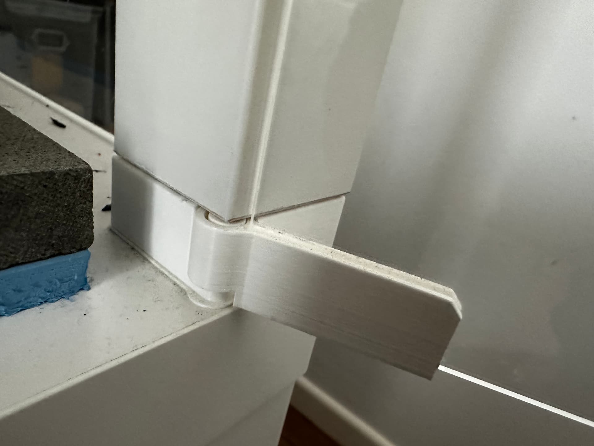
Assembly, Lid, fasten rear extrusion frame

Attached Panel Corner Clip Hinges to Lid’s 2020 rear frame assembly. Lid frame was fastened with blind joints.
2020 extrusion holes were too loose for M5 tap, but too tight for M6, so had to rebore with 13/64" (5.16mm) bit before M6 tap. No cutting fluid available, so used cooking oil instead, seemed to work ![]() . Soaked/wiped up most of the oil, but didn’t degrease or threadlocker yet, am expecting more changes.
. Soaked/wiped up most of the oil, but didn’t degrease or threadlocker yet, am expecting more changes.
Hinges don’t have any adjustment slots, so had to precisely cut the extrusion in order for Lid and main body width to be exactly the same. Ideally would’ve batch cut Lid X extrusion at the same time main frame’s X extrusion is being cut. Had no idea build would end up here back then. Have ideas to workaround width mismatch between Lid and body, let me know if interested.
Parts
- 4x 2020 L-Shape Interior Inside Corner Connector Joint Brackets, helps prevent extrusion twisting when being tightened/used. Tried printing a 2020-blind-joint-alignment-nut, but was too fragile.
- Bunch of 2020…
- 2x 145mm, maybe, still figuring out how Polycarbonate and extrusion should connect.
- 2x 424mm for my build with 1/16" interior panels. Note a regular sane 250mm build would have Lid rear X extrusion of 420mm instead.
Maybe, thanks for the suggestion. You have me thinking how some aspects of the Prusa enclosure could help with how I connect Polycarbonate and extrusion.
Assembly, Lid, mount polycarbonate to extrusion
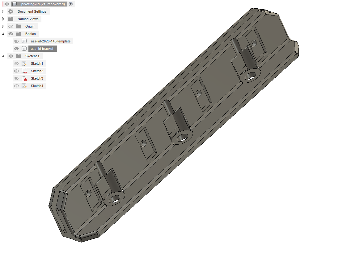
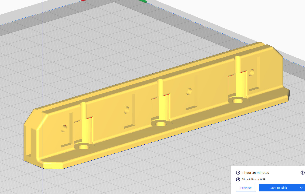
Created Polycarbonate-to-extrusion bracket to design my way out of not having done big design up front. I failed to fully consider ideal lid dimensions upfront, or best way for lid to adjust, pivot and rest. Bracket design involved much fudgery. Can tell from my posts, but have been mostly agilely sprinting my way through this build, completely winging it, so am having to pay for some of my earlier myopic decisions.
PETG bracket squishes/compresses nicely, acts as a washer/shim preventing bolts from overly compressing and cracking polycarbonate when snugged up tight.
Parts
- 6x M5x8mm button head bolts
- 6x M5 slide-in nuts, or roll-in nuts.
- 8x M3x12mm button head bolts, ideally flanged.
- 8x M3 T-nuts
4 Likes
Did any of the gas struts work?
1 Like
Yeah, kind of…
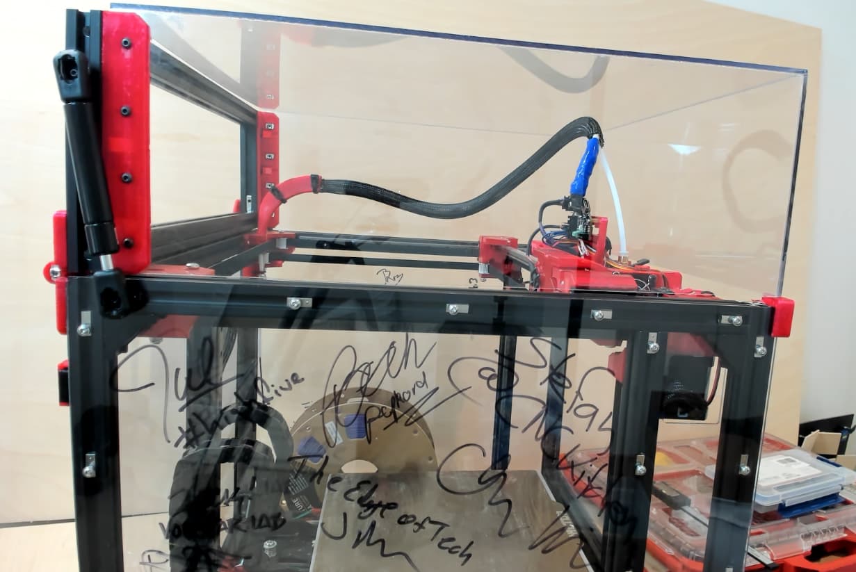
Assembly, Lid, Gas Struts for hold and slow close
Parts
- 2x 30N (7lb) Gas Struts. Remove spring metal clips and drill ~3.4mm holes, ping me if you’re at this point and need details.
- 4x M3x16mm button head bolts, ideally flanged.
- 4x M3 Slide-in nuts ideally. Maybe roll-in, but not T-Nuts.
- 4x M3 Nuts to secure M3 Bolts to Gas Strut end.
Edit 1: Tried 40N (10lb) on just one side (20N on the other), this results in Lid holding position at any angle. Definitely an improvement over 2x 20N Struts which drop too fast when Lid is < 45 degs from horizontal. However…

Look at Orange circle in the pic, unfortunately the printed hinge isn’t strong enough to resist entire Lid being lifted up ~3mm ![]() .
.
So, am reverting back to 20N Struts on both sides until if/when more rigid hinges are being used. Maybe regular metal 2020 to 2020 hinges with small plates that will clear the panels, or, mount regular metal 2020 hinge on 4mm thick printed packer/spacer for panel to slip under. Using separate printed regular corner panel clips.
Edit 2: Ideally Struts would be inside the lid, making for a cleaner exterior. Am having to work on some other stuff for a while. So…
A Beer/Coffee bounty, and bragging rights awaits anyone who comes up with model(s) I can print that will enable Gas Strut to be mounted internally (and not tear Lid apart). Welcome to mod the parts am using currently if that helps. Something that mounts the Strut here maybe…

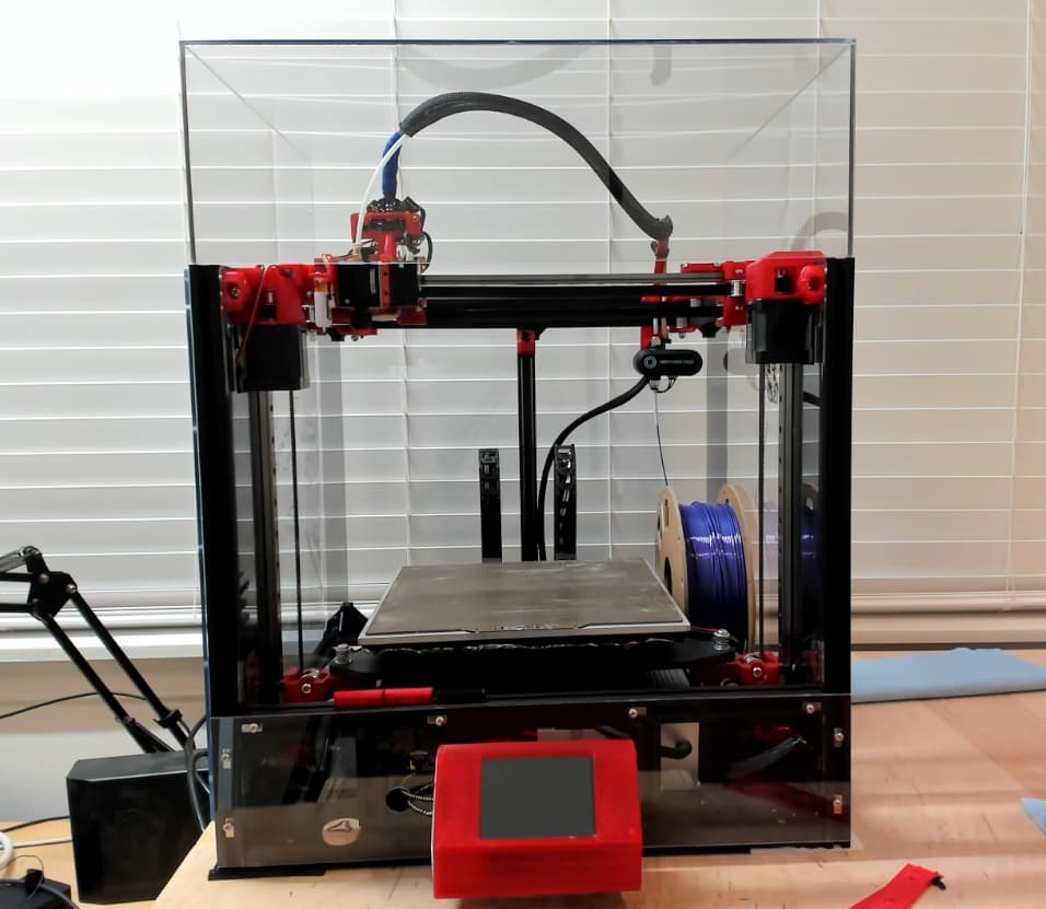
Edit 3: Settled on 30N. They’re strong enough to hold Lid open > 30 deg. Lid closes at exactly the right speed I wanted, silky smooth descent. Strut strength was trial and error matched to the weight of my Lid consisting of 1/8" Panels. Also tried 20N and 40N, but 30N was right for my build.
Beer/Coffee/bragging-rights bounty still available for nice internal Strut design…
5 Likes
You’re doing awesome stuff.
1 Like