Yes. That’s the current setup. I think that picture was taken when I was testing the LEDs.
1 Like
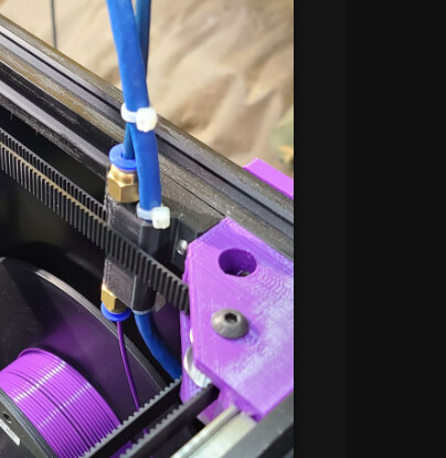
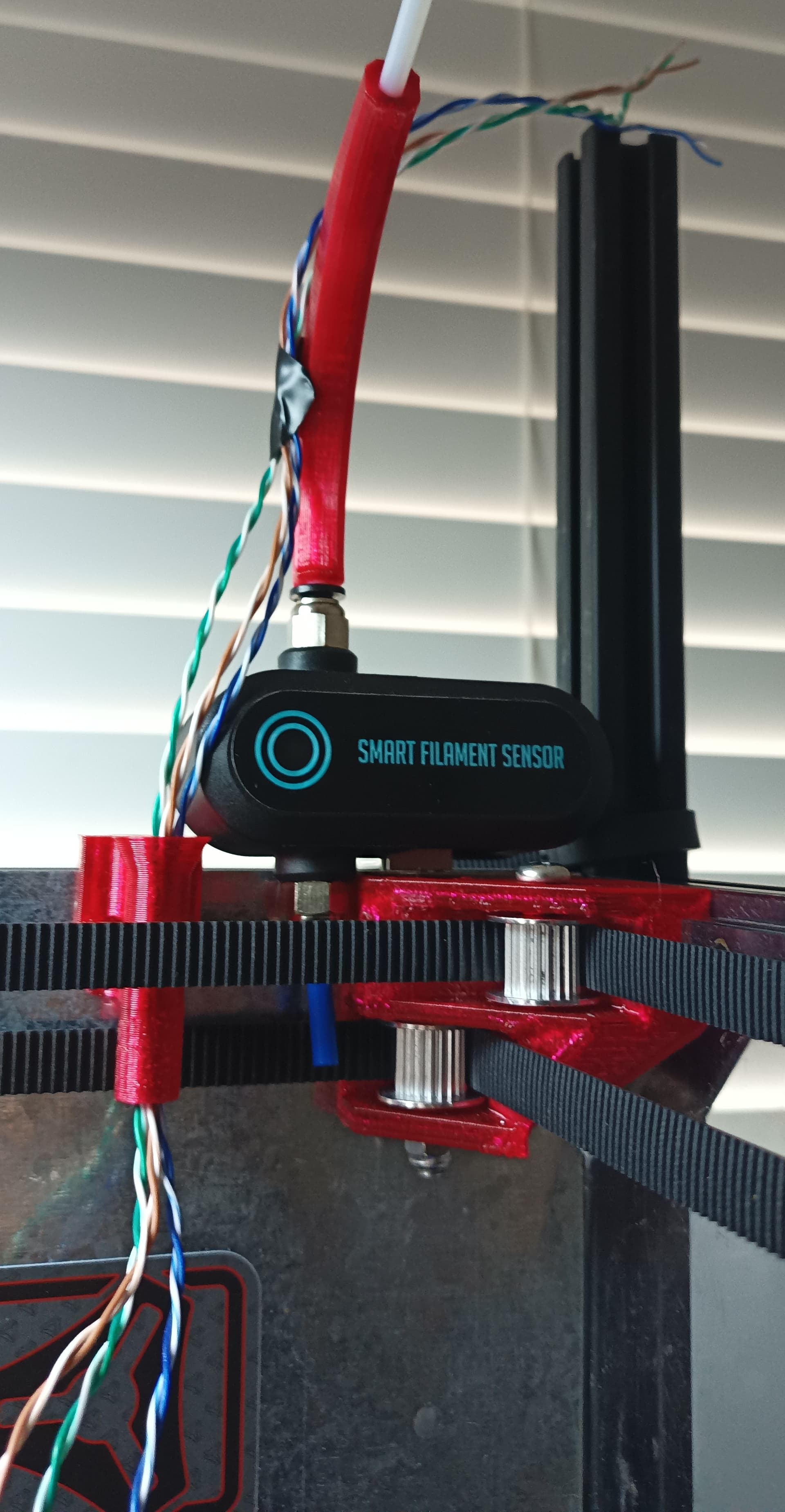
@azab2c I modified the idea of @niget2002 's bowden holder and added a second hole for my CAN cable so it was a bundle. I felt it gave the cable a little more structure and took strain off the connector (had issues with this pins).
I like where you are going with the elbow to guide the tube flatter in the enclosure though!
1 Like
Awesome, was wondering about something along these lines today since I have wiring for smart runout sensor around there too. Will share details on runout sensor if/when I get it working.
Curious to see your updated setup, cheers!
@azab2c here is my current setup.
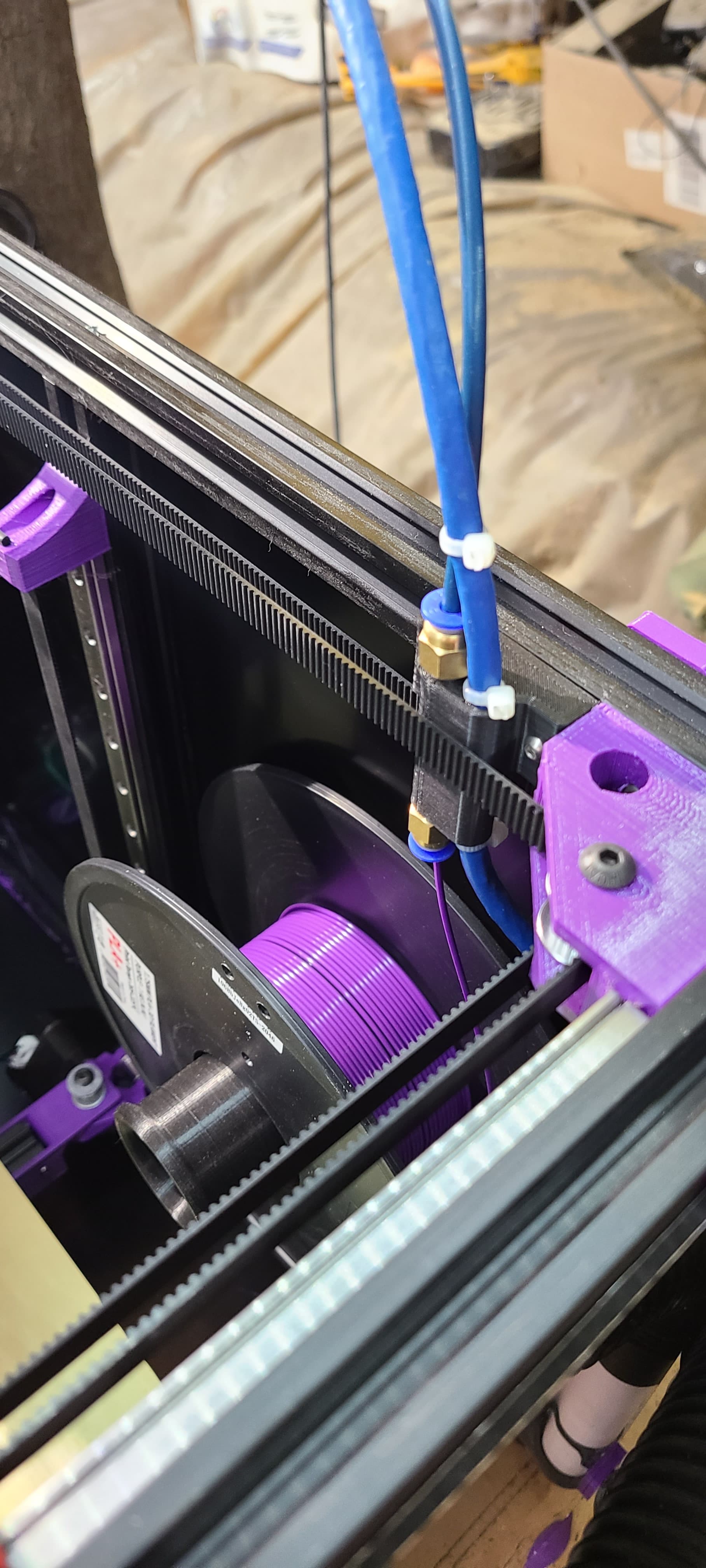
I had a bunch of capricorn tubing around so I used it. Probably dont need it and I should shift to the tubing you are using to reduce drag.
2 Likes
Curious about lighting/LEDs too and what you/others end up with.
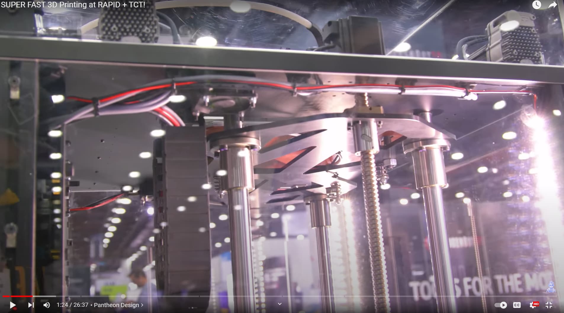
Personally, was originally going for a Pantheon look for the top lid, something like…
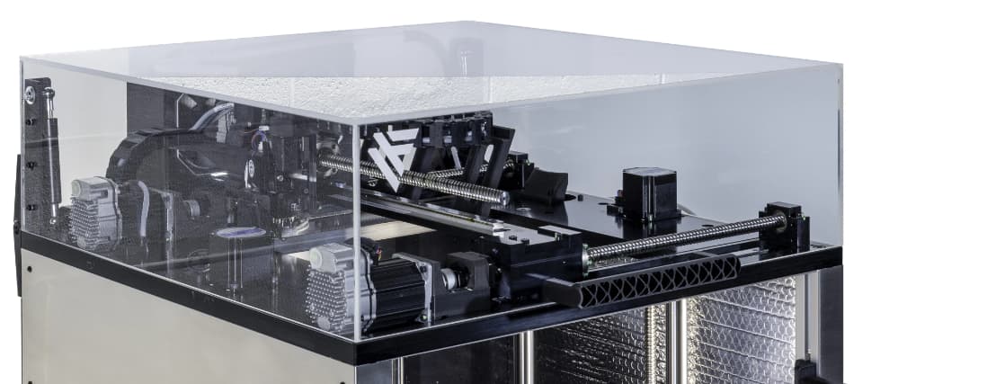
Pantheon’s lid looks cool, but then lighting would need to be below the lid, maybe that’s ok? This is their glaring setup…
Was chatting with Barry at RMRRF, I shared concerns about my ability to neatly weld polycarbonate panels into a lid. He suggested considering fallback option of using Alu L brackets to hold LID panels together, that would be neat and very doable.
That fallback option would also create a place/space to run LED strip lighting above the tool head, pointed towards the bed. Casting shadows on the part, which might cause shadows/problems with AI/ML based fluff-up detection if/when that gets added.
So, will likely place lighting somewhere optimized for the camera and viewing from the front.
Am still deliberating, procrastinating and navel gazing on this one…
1 Like
I like this, hoping to get something like this working too. Then, maybe, eventually, mod the Back Corner Right part to have wiring and PTFE guide features integrated? Am thinking the elbow guide might move better, and be neater too.
1 Like
If there is enough room in the part I don’t see why that would not work! I just pulled it up and it would totally work. Curious @vicious1 what is the zip tie channel for?
1 Like
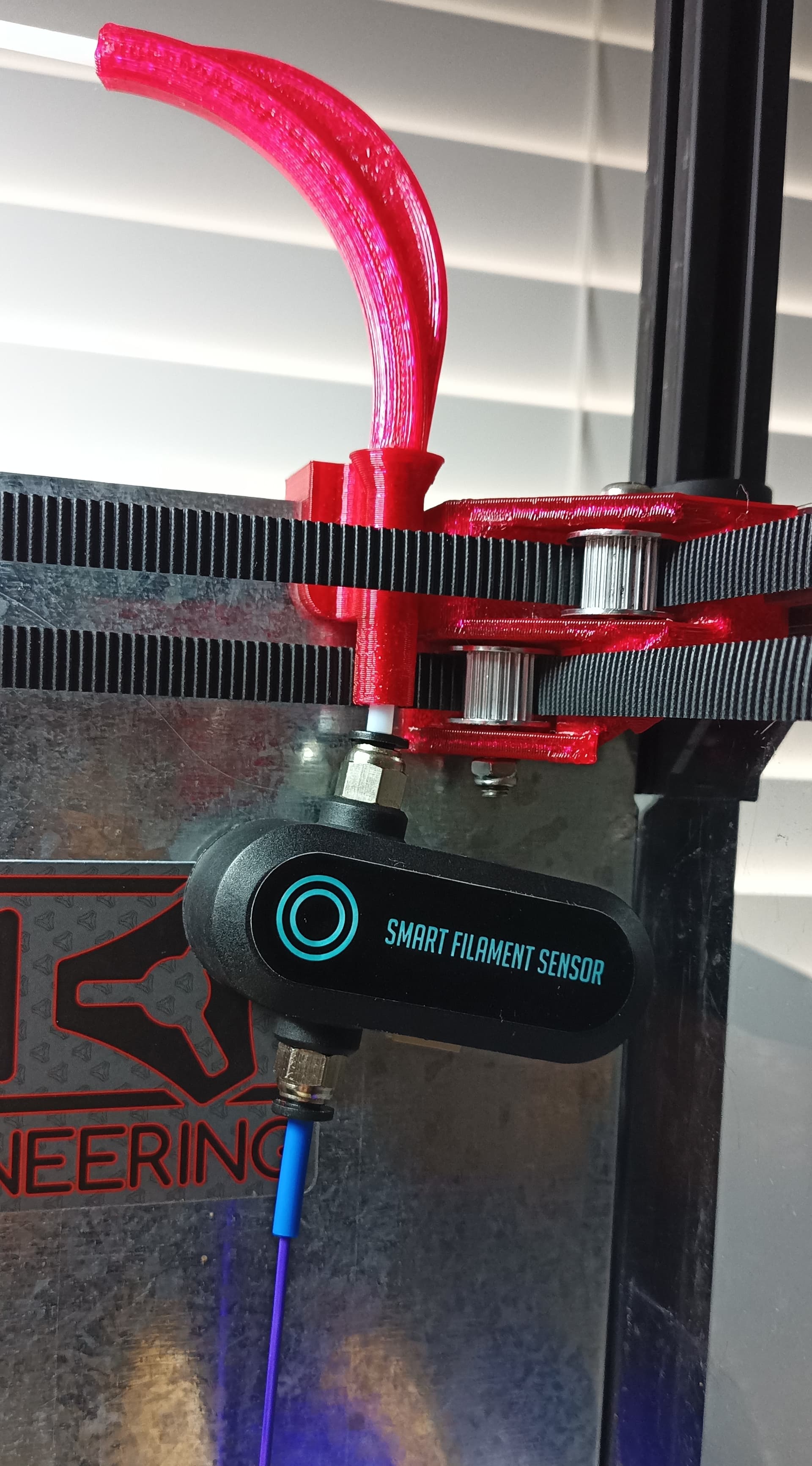
Am currently using a motion based filament sensor. It’s pretty hefty and chonky, limiting layout options. This is partly why I didn’t try modding rear right corner yet. Would happily swap sensor for something functionally same/better but cheaper. Having solid panels on frame interior is restricting my options as well .
Considered different top mounting options for the sensor, would impact overall lid height, still haven’t figured out way that made sense to me, yet…
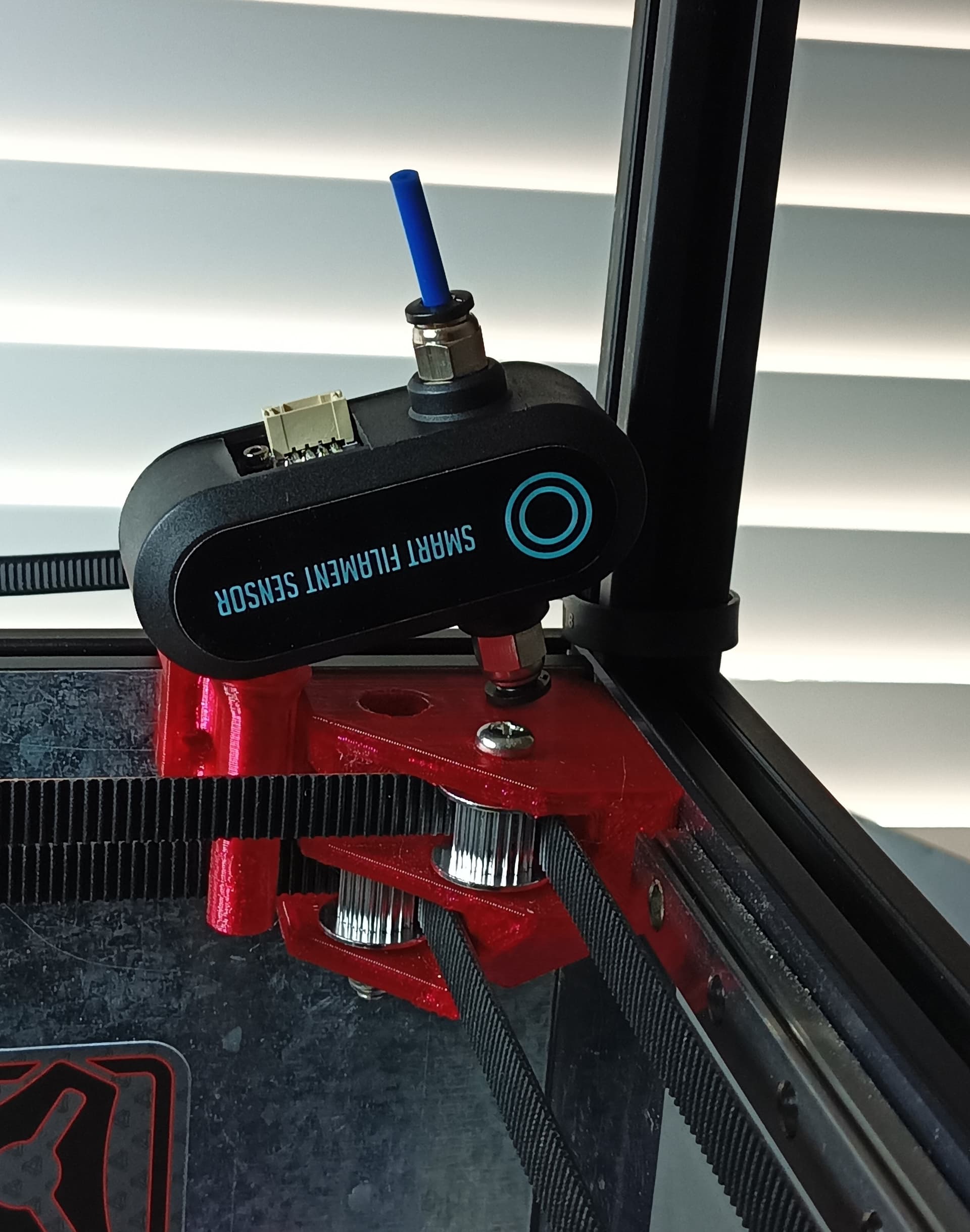
Partly refrained from attaching anything to Rear Right Corner part to avoid wiring/filament motion from contributing to belt vibrations, no idea if that’s a valid concern?
I think you will have a hard time getting cheaper than that sensor.
I expect that you will not see any issues with vibration transfer from filament movement. That part is bolted to two opposing plans and with panels for rigidity I cant see how it would make a difference.
I do like this idea though. If the right rear mount could have a mount for the sensor that would be ideal!
You could move it further from the corner, closer to the spool.
They’re 12v LED pucks designed for boats/walkways. They’re not RGB or anything fancy. Just lighting so I can see what I’m doing. I 3d printed a mount for attaching them to the extrusion.
I used a 12v buck converter to step down the voltage from my 24v power supply.
IF you’re going to make a basic PTFE guide, but then allow scope creep for should/nice-to have things like… routing wiring, mounting a motion based runout sensor, including zip tie slots, replacing sensor housing parts to keep a slim profile, etc…
Then, do consider ensuring the basic requirement of PTFE guiding will still work ![]()
v3 render looked great, but failed in reality…
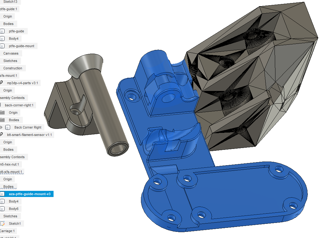

v4 should work better…

1 Like
I like this routing for the CAN wire. Mine goes straight down to the base and under so it will be a straight shot.
Are you using this as the back cover for the runout sensor?
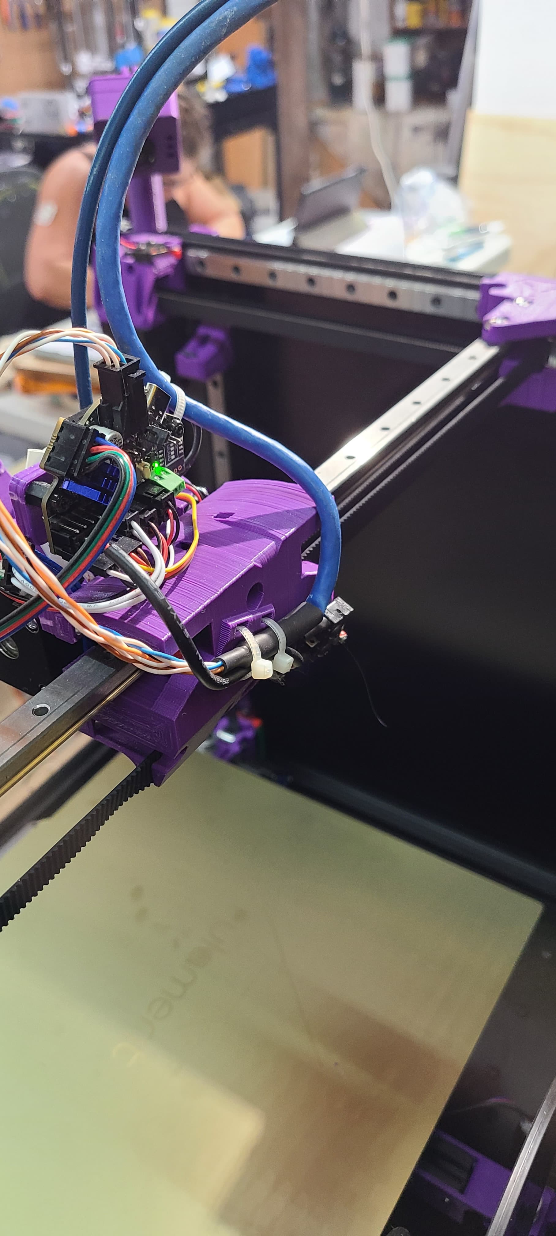
Thanks Mike, yep, am doubling up the mount as a back cover for the runout sensor. Alternative was to create a clip holder or something. Also included recessed channel within the back cover to help hide and hold/strain-relief runout sensor wiring.
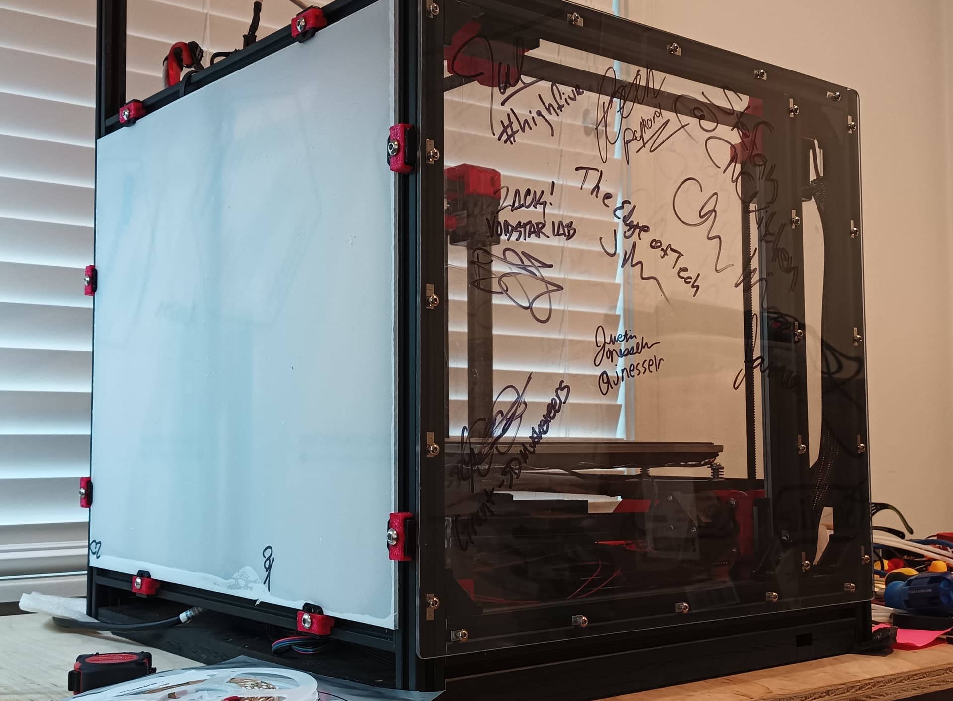
Have interior sheet metal panel that the mount is resting against (will share pic), the panels helped with squaring, but I don’t like how the interior panels restrict being able to easily mod the interior. I guess interior panels would be great if you have a fully considered design that won’t be modified.
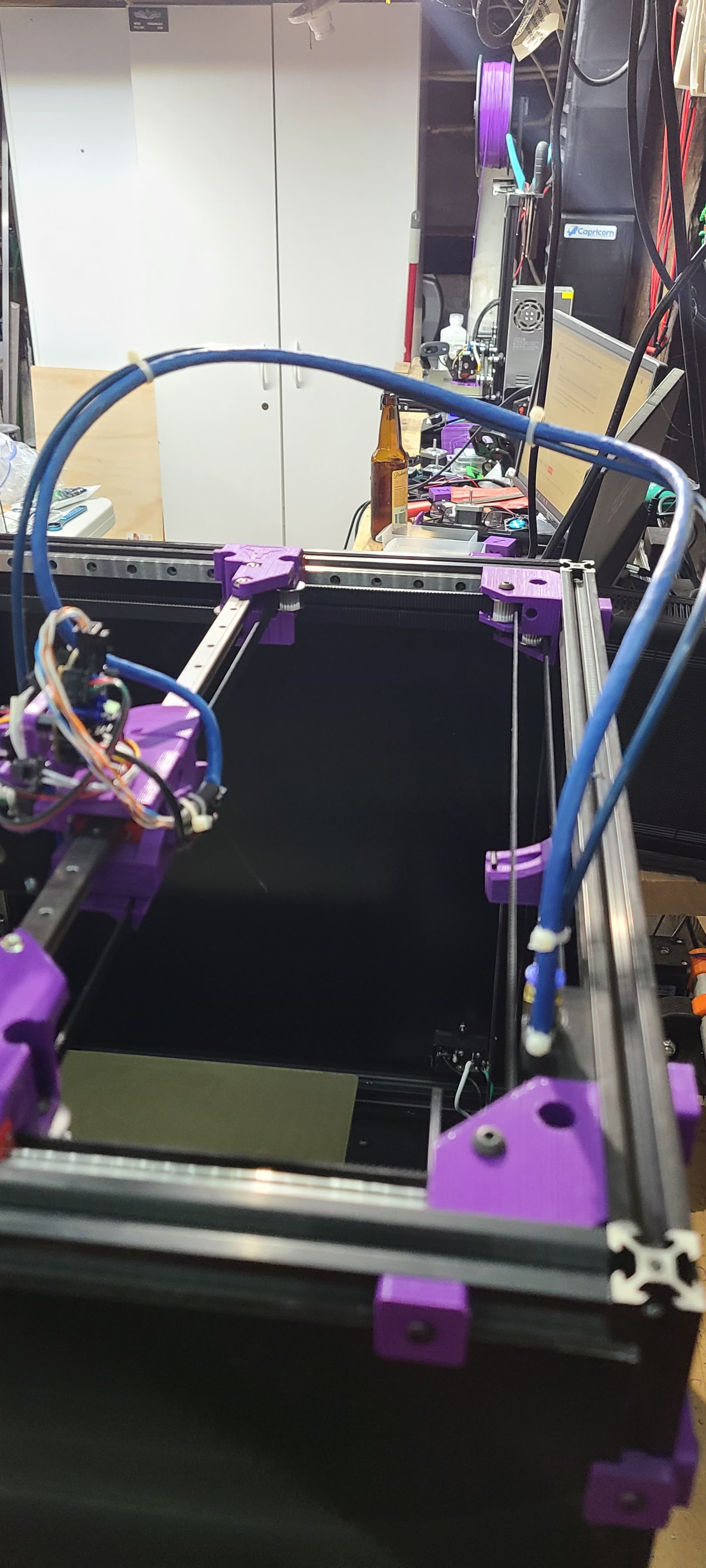
Planning to run CAN and Runout wires through new hole in the interior panel, then route CAN and Runout wires along the extrusion down to the base where wiring/controller barely fit under the plate/z-posts. Will update when done… Suggestions appreciated, cheers!
This is where I ended up…
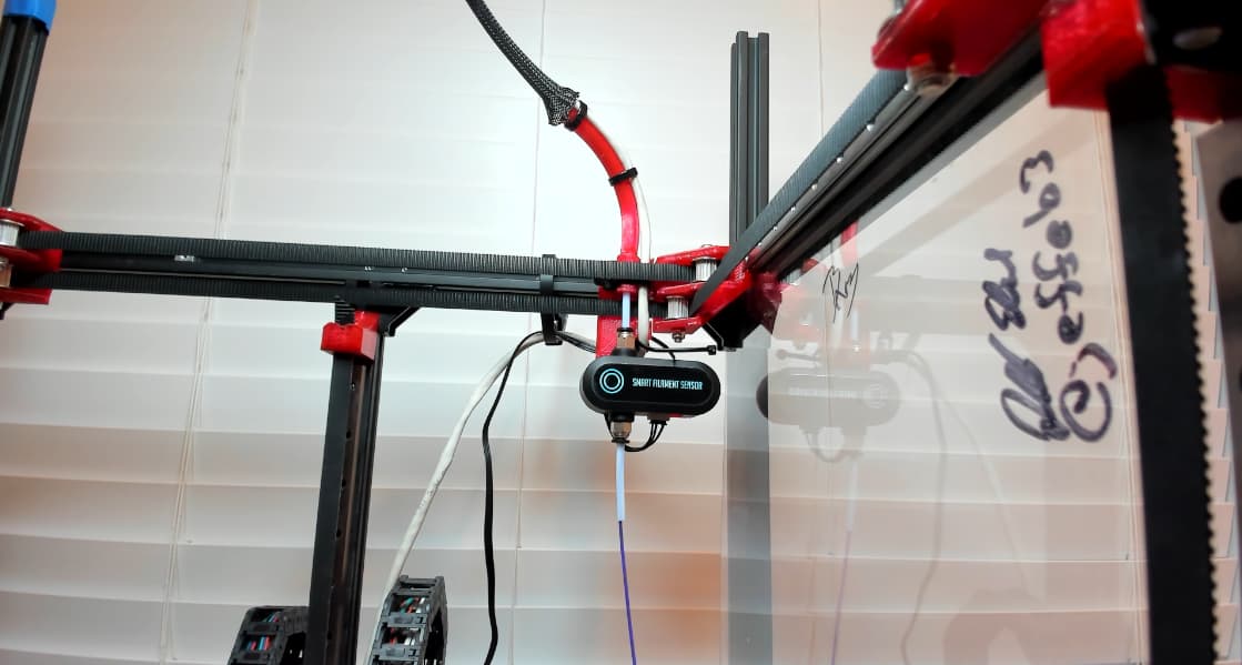

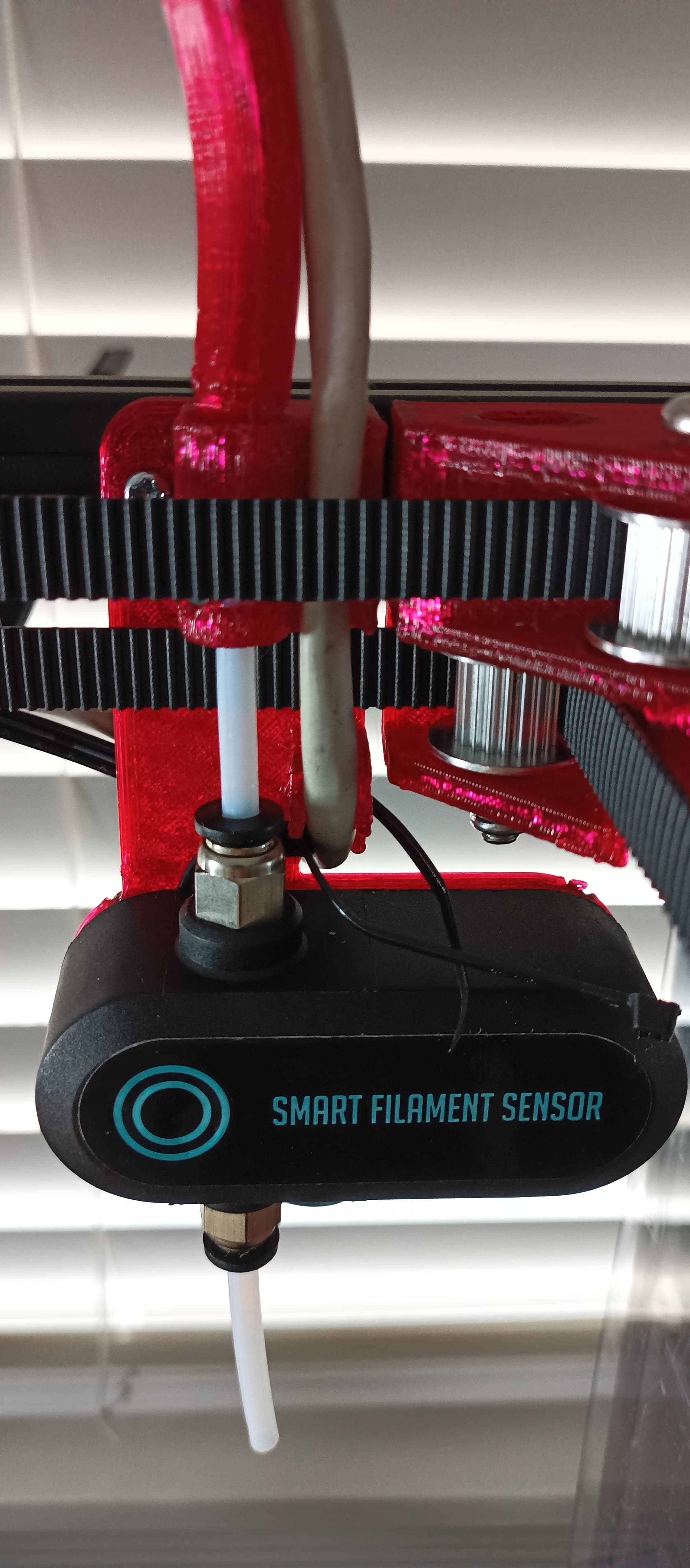
Shared models in my usual V1E mod repo at https://github.com/aaronse/v1engineering-mods/tree/main/mp3dp-v4/mods/filament-guide, and on Printables.
Works, but the straggler CAN and Runout Sensor wires need extending/replacing so they can be routed/mounted neatly along the extrusion to the controller box resting under the bed plate.
5 Likes
Some guys scribbled on your printer. ![]()
1 Like
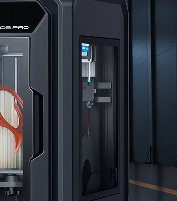
Just noticed my setup ended up with filament spool placement, runout sensor and PTFE routing being similar to Creality Sermoon D3 Pro’s approach. Just stumbled across Sermoon earlier today.