Curious if anyone’s created/seen compact enclosable PTFE guide and gantry wiring setup they really like? Something reliable that doesn’t negatively impact quality/speed, or make a racket slapping PTFE against the panels.
Looking to enclose my MP3DP v4 and tidy up my PTFE/Wiring setup. Typical 1000+ mm/s 3D printer builds seem to be open with massively long lengths of reverse bowden PTFE towering over the top of the Printer. Would like a compact setup to help minimize overall height, helping reduce space taken up, and reduce heat energy required/lost.
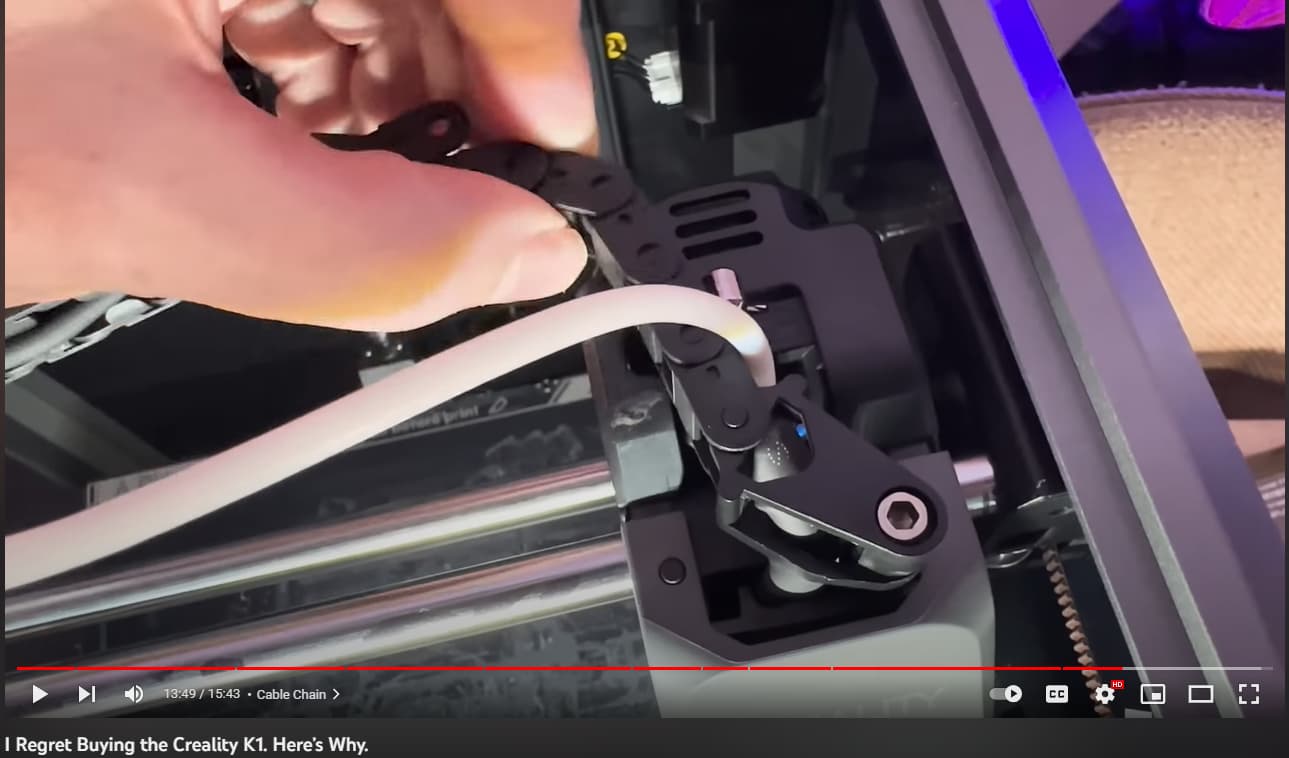
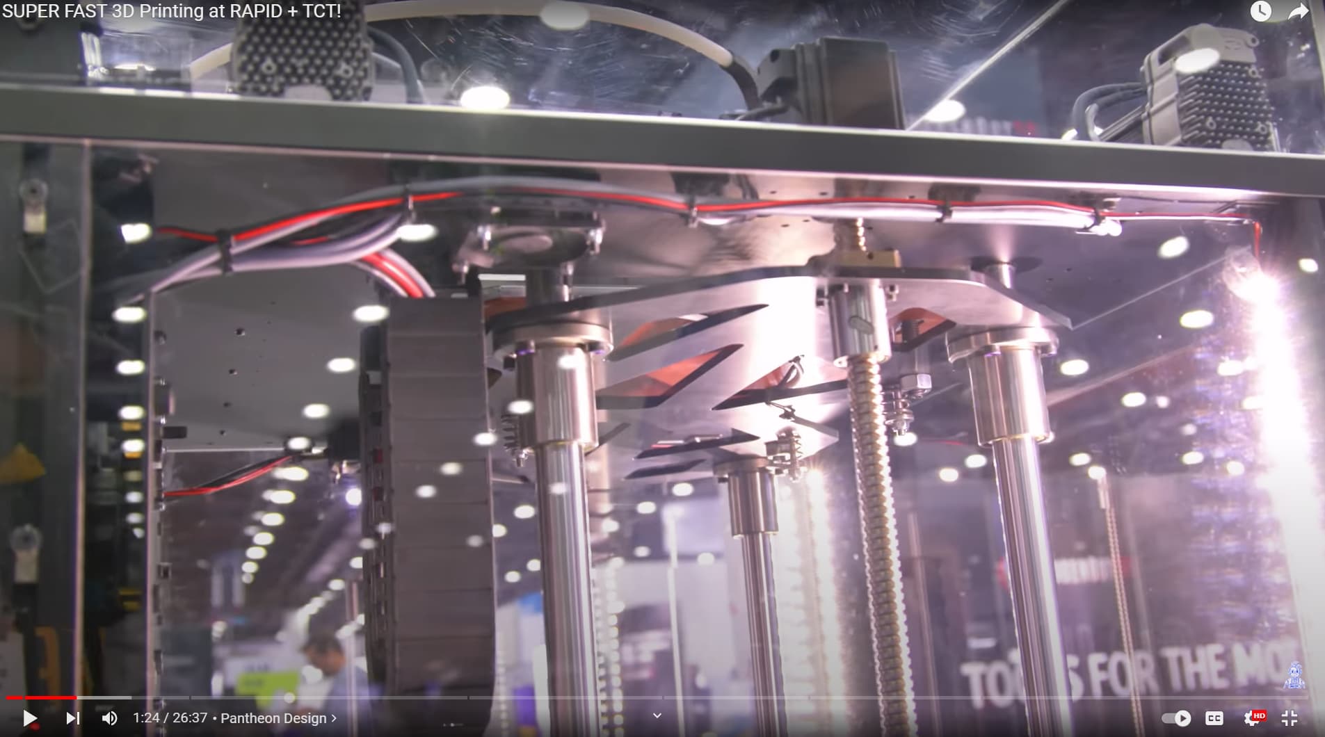
Similar to Bambu setup, but seems to have design flaw where drag chain can cause PTFE tube to come loose. The drag chain can unintentionally hit the PTFE disengage switch on the hotend, details in this YouTube review by 3D printing zone.
I have not started my 300^3 build yet because of this. I want to enclose it for sound mostly, maybe some ASA, but I am not sure how tall I need to go to accommodate the umbilical.
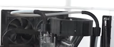
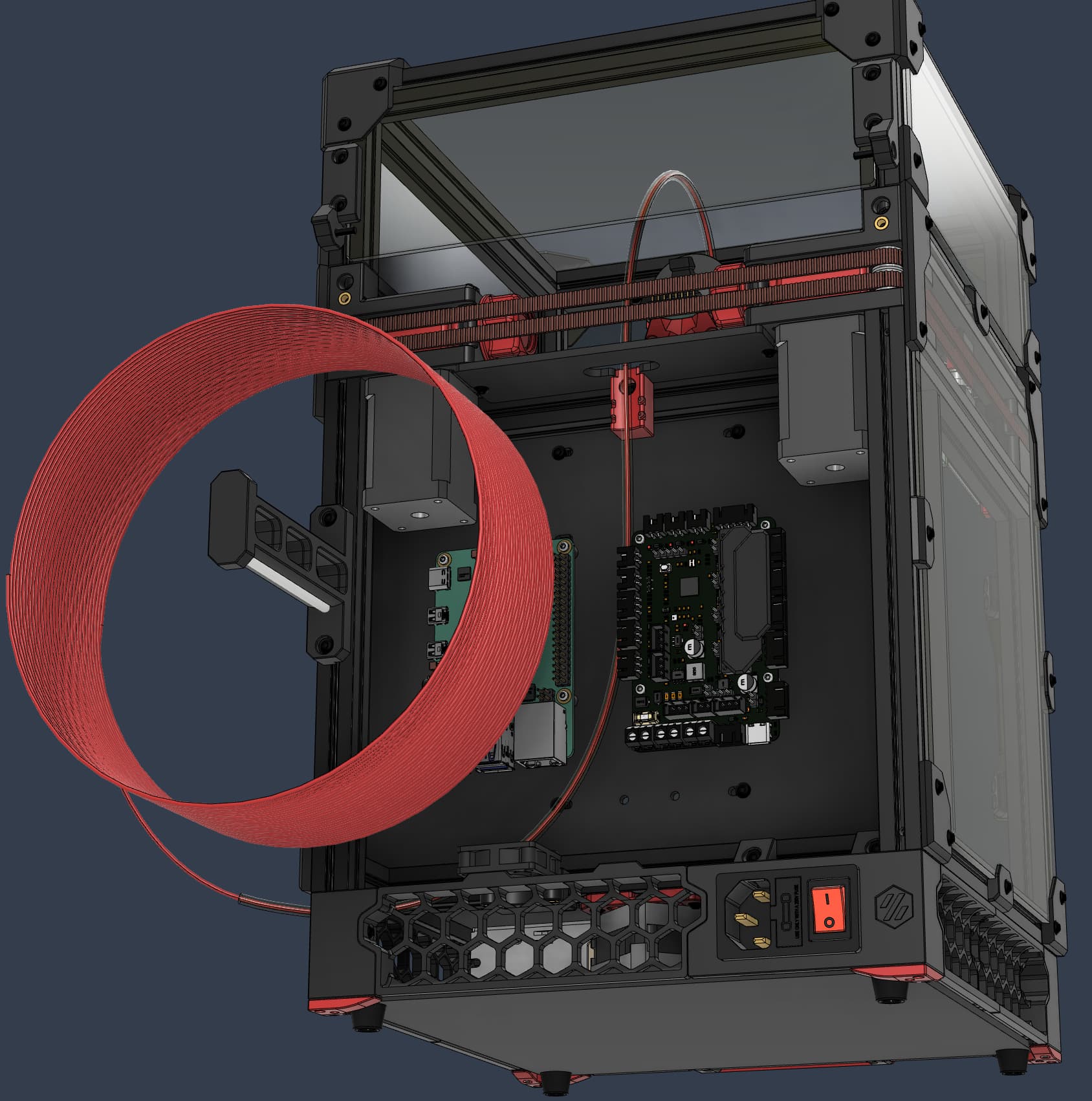
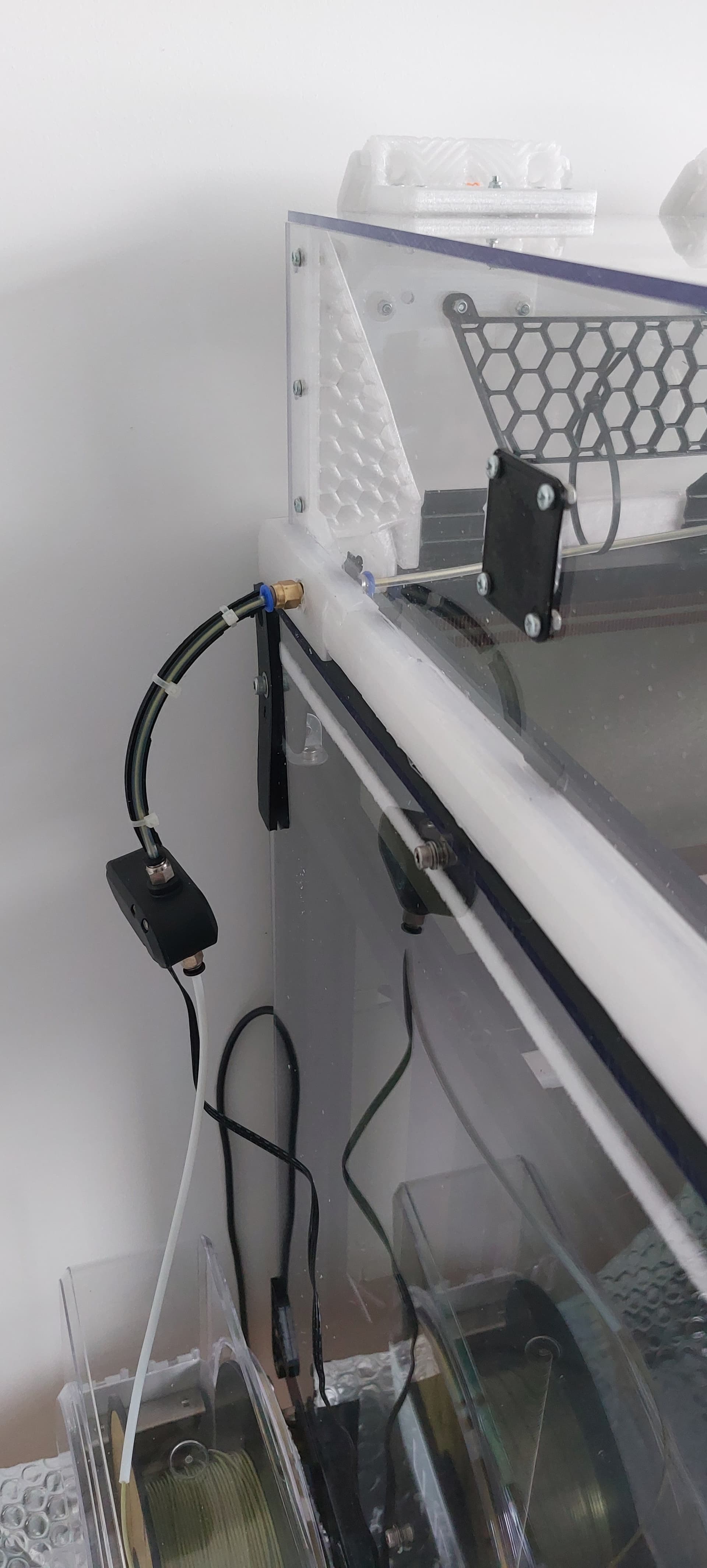
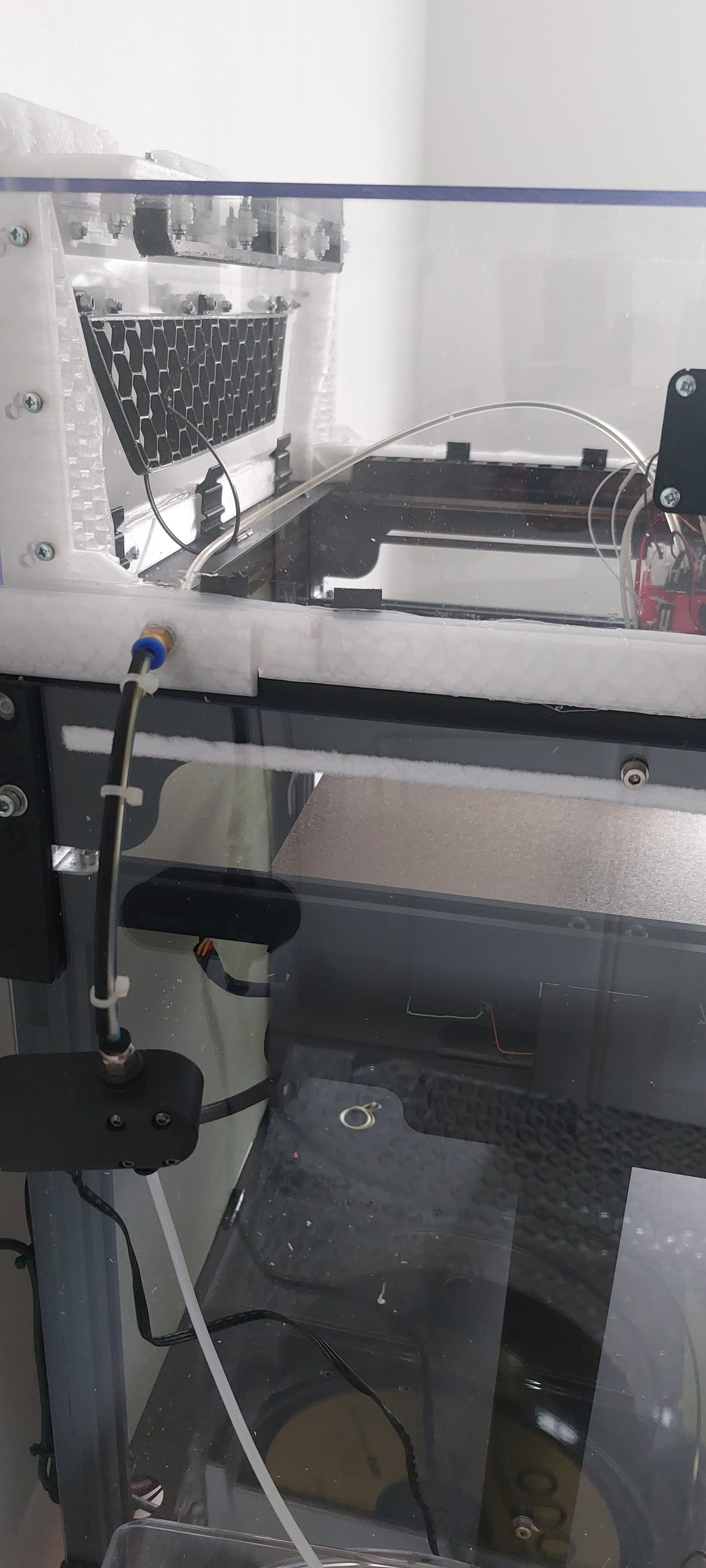
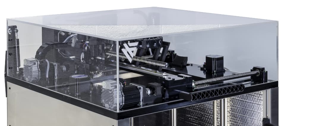
I tried quite a few different designs after enclosing my Twotrees Sapphire Plus. The best solution i’ve found is a combination of printed elbows (eventually i ditched the elbow at the carriage end as i’ve built in a bowden guide to route into the extruder (a Biqu H2 500)) , careful placement of the bowden entry (close to home) and a flexible rear panel protector.
The top cover extends 140mm above the top of the carriage and has around 20-25mm clearance.
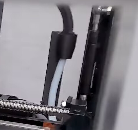
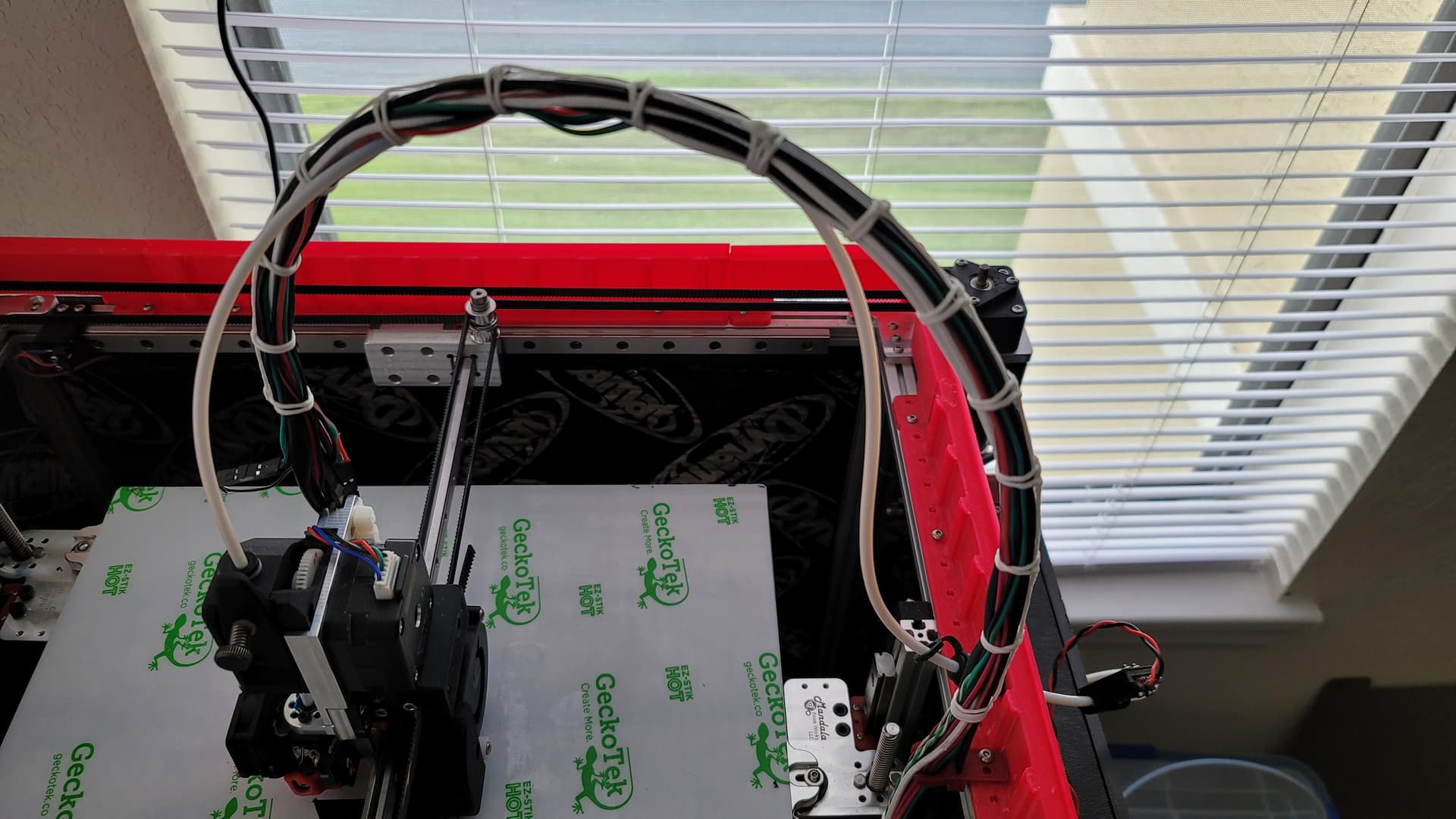
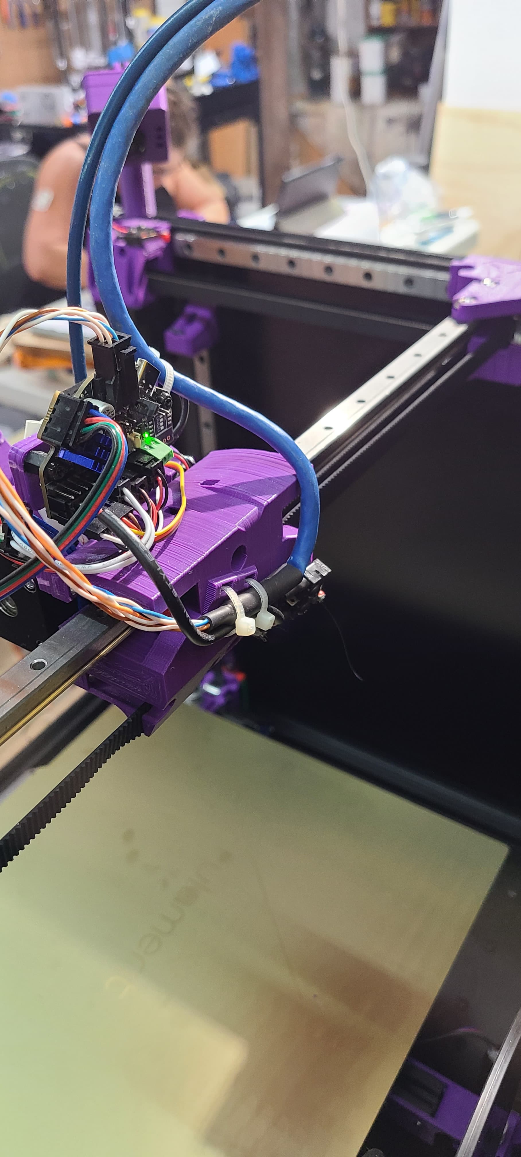
p.s. The loose tie wrap also plays a functional role to keep the bowden out of the way of the fan and switch connectors on the top of my carriage PCB when homing.
Bed size is 310x310 and bowden length from point of case entry to extruder is 450mm
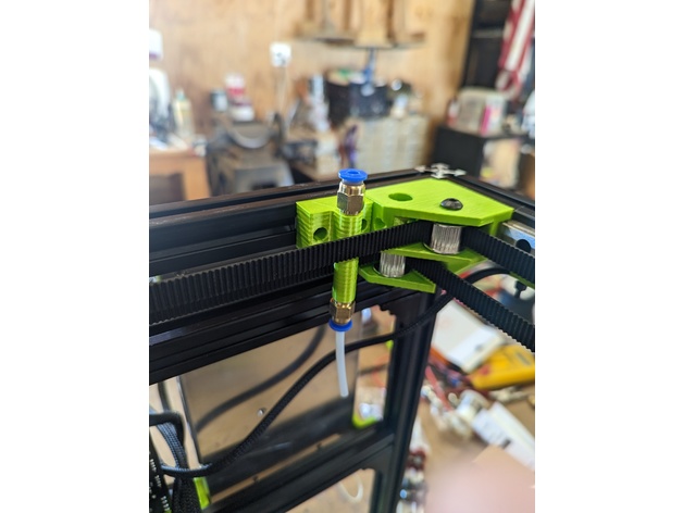
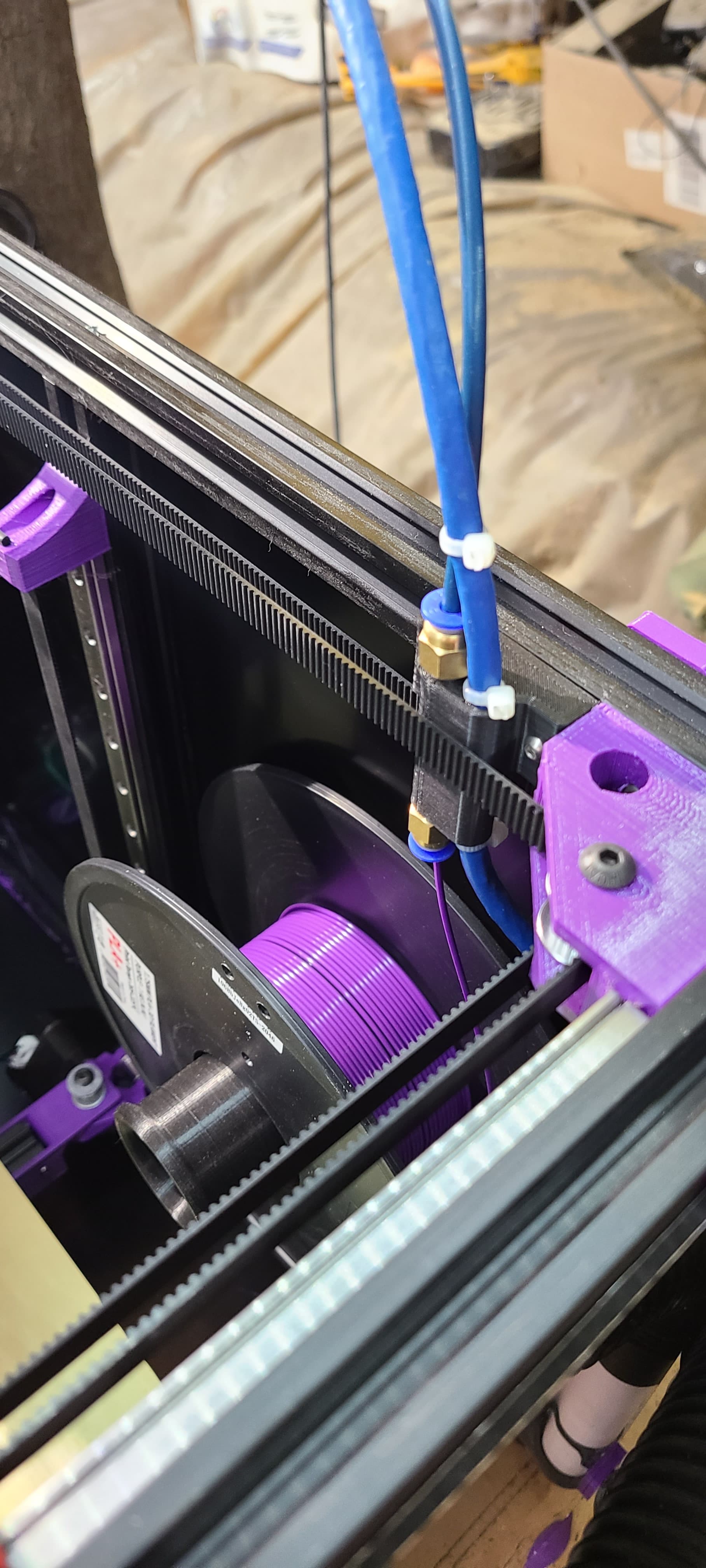
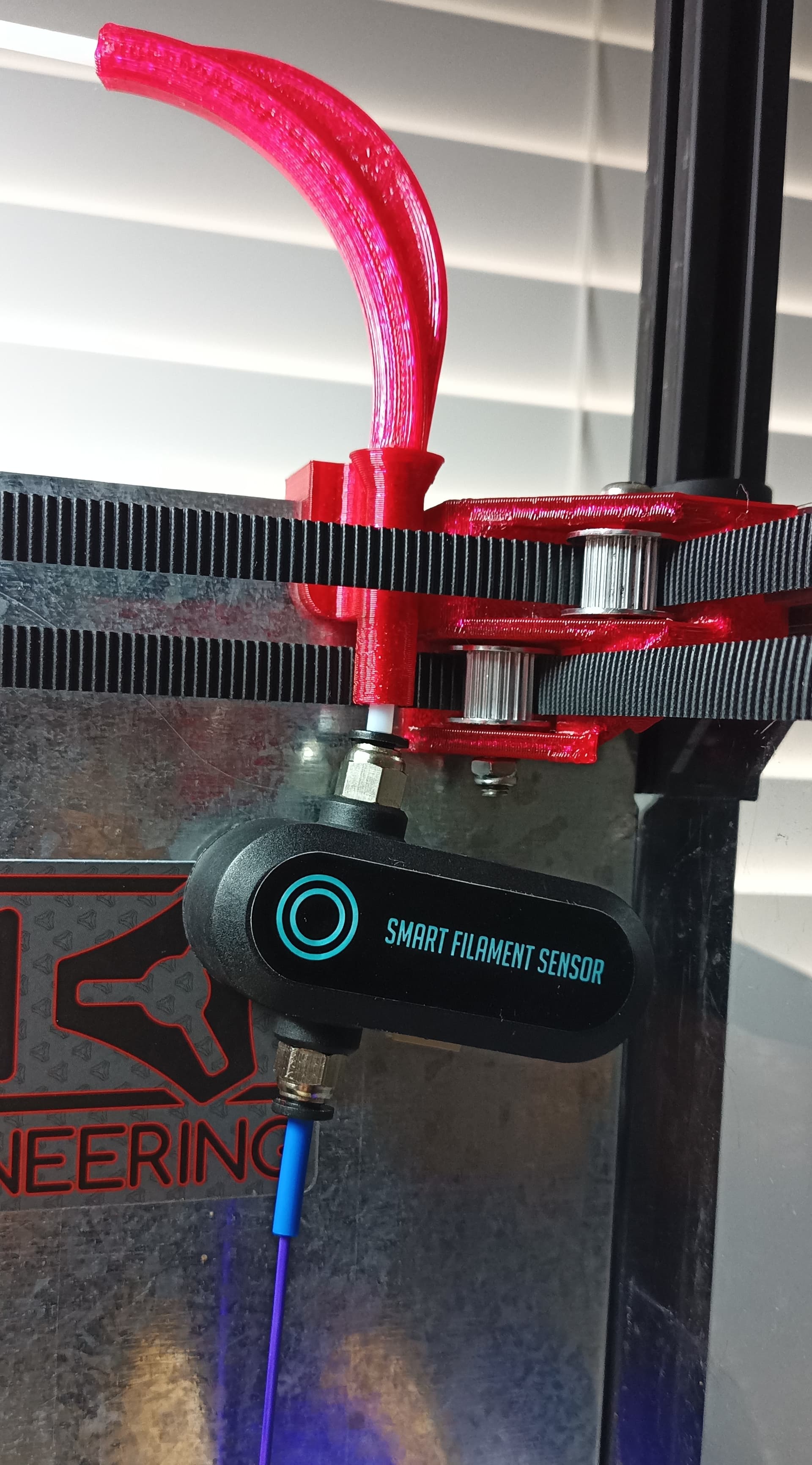
The PTFE tube 3x4 (3mm ID, 4mm OD) Steve recommended is definitely more flexible than standard PTFE 2mm ID, 4mm OD or the popular Capricorn PTFE. However, the wall for 3x4 so thin that pneumatic fittings will probably cut through if tube is overly rotated/worked overtime. So, currently figuring out alt mount/stress-relief options that will also accommodate filament runout/stuck sensor…
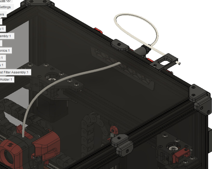
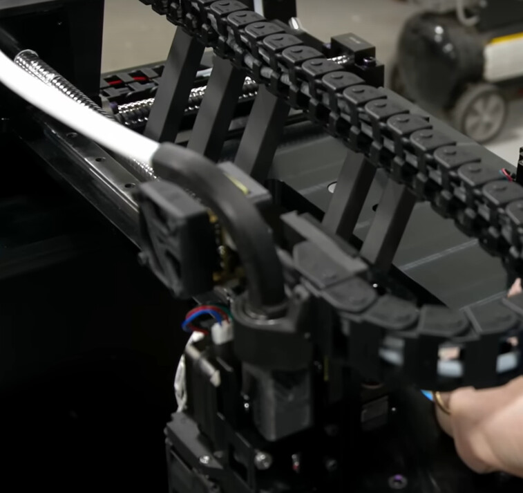
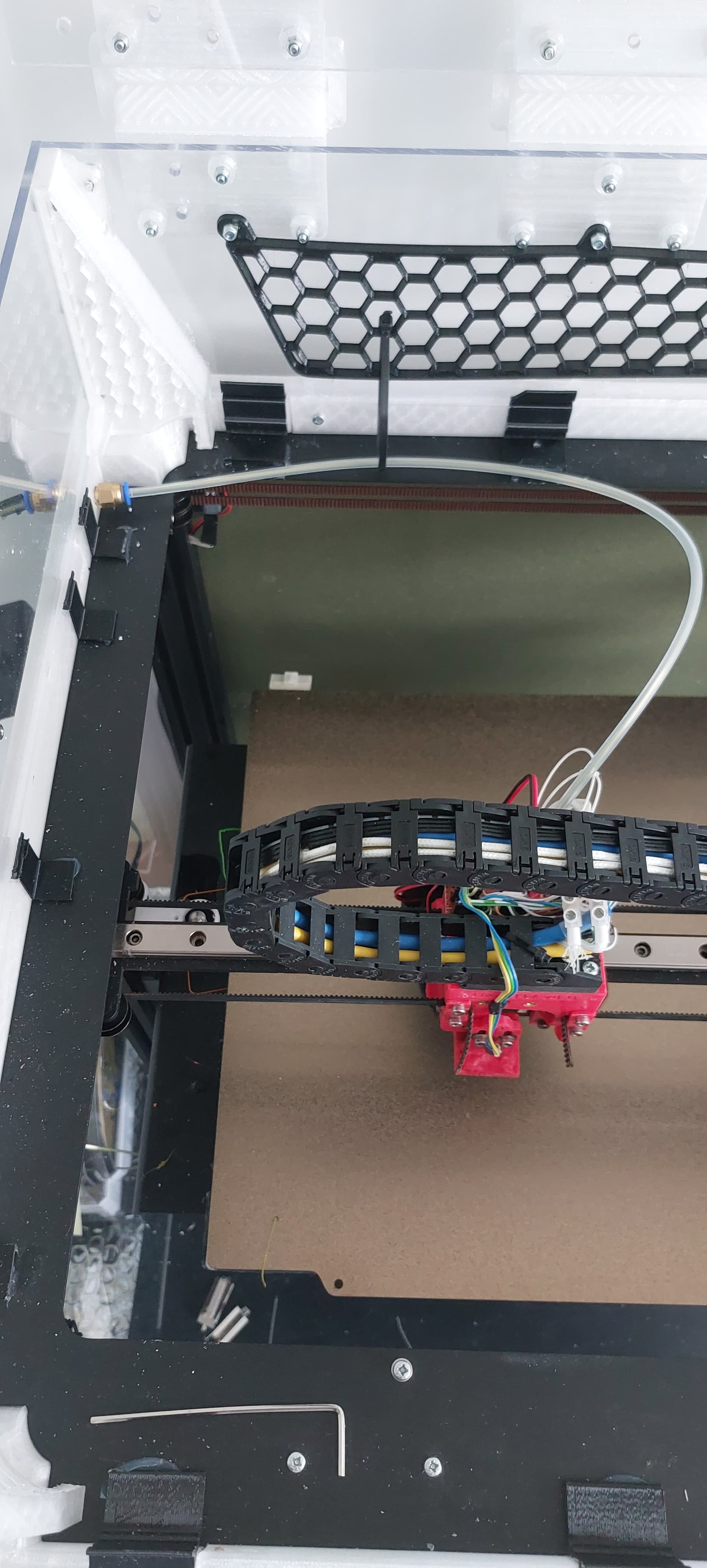
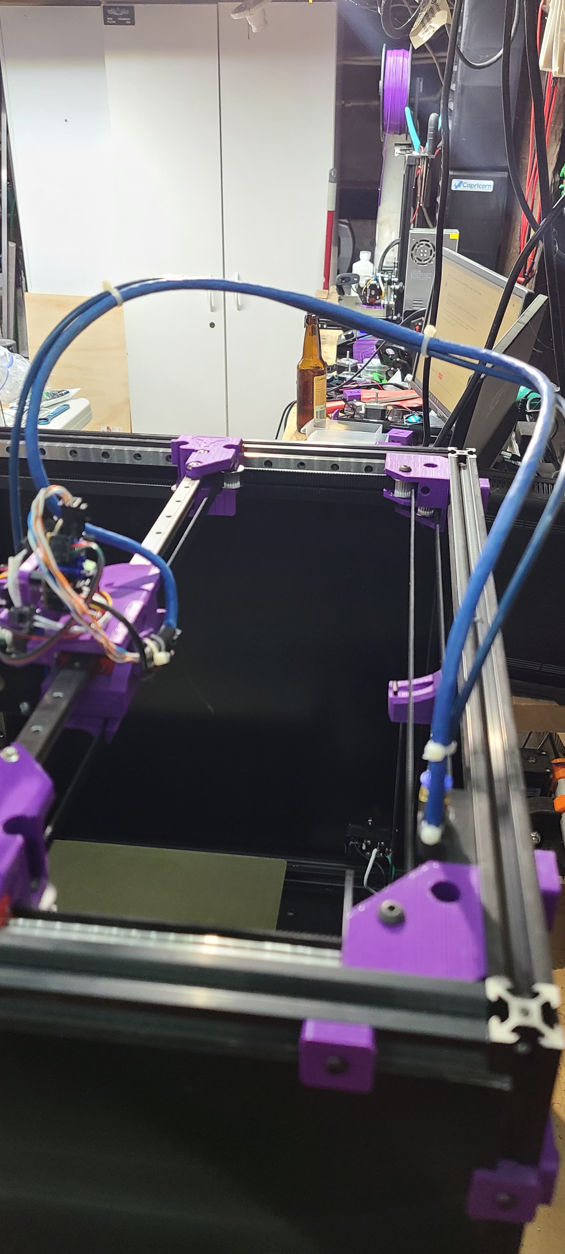
I let the umbilical slide in and out the back of the machine instead of affixing it anywhere. It keeps it from tugging on the gantry. I 3d printed a guide slot that it slides through.
The PTFE is light/soft enough that it flops and rotates as needed.
I think I only made my lid 150mm and there’s more than enough room for the PTFE.
Oh. And if you mount the filament inside the enclosure, then you don’t have to worry about getting the filament outside of it.
I do plan on re-designing the umbilical guide. I want to enclose it the rest of the way between the inner chamber and the electronics chamber on my build.
Cheers for the info David, this your current setup?
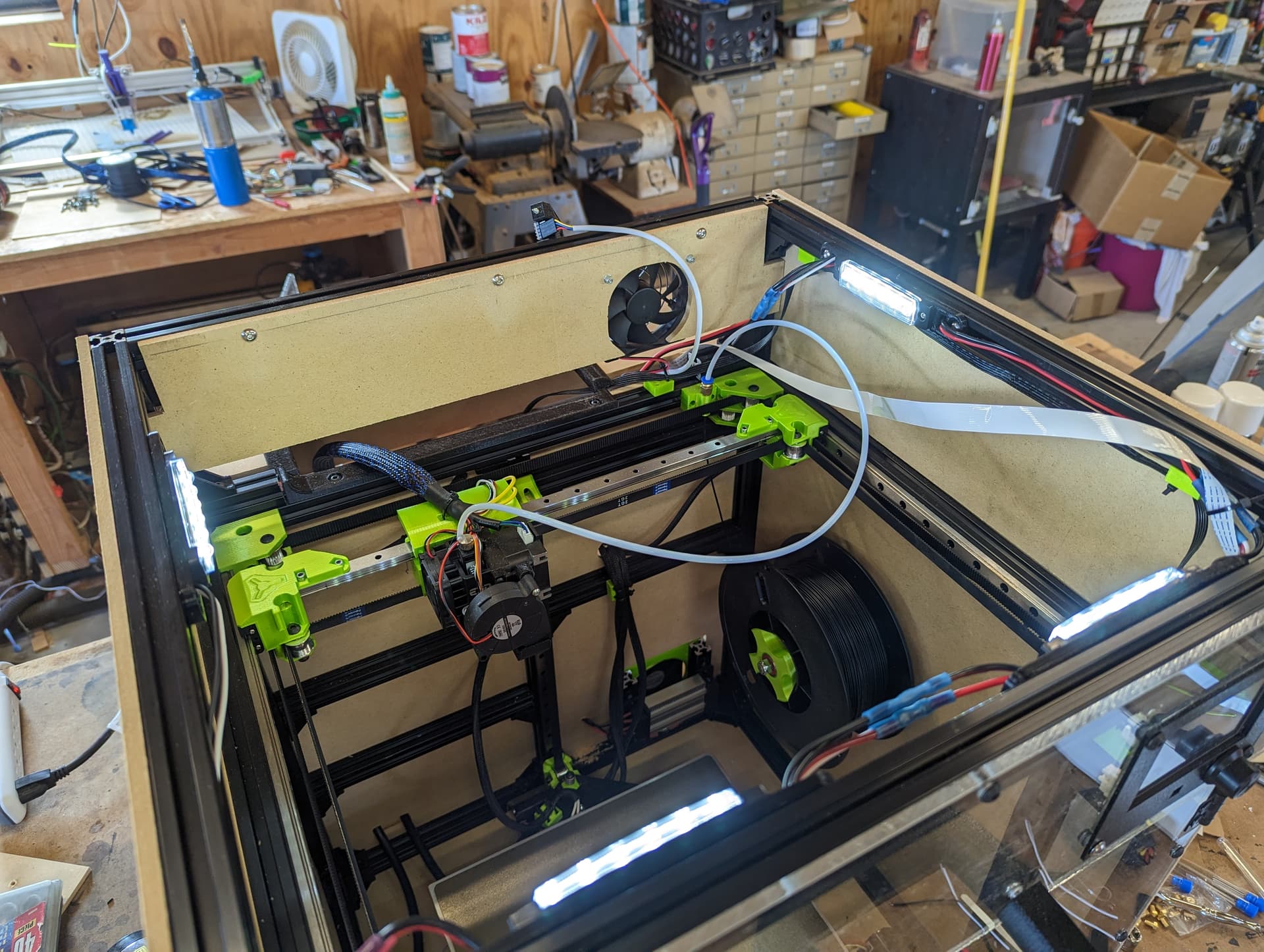
Short motion test video, mainly to observe and understand whether wiring and PTFE setup (3mm ID, 4mm OD) are good enough…
Already cut polycarbonate panels for a lid ~145mm high, but looks like ~115mm, or shorter even, would work too.
Still tweaking and figuring out misc settings, e.g. “1000mm/s” was configured, but not met, acceleration is too low.
Am curious what max motion speeds/accelerations folks are getting with their MP3DP v4 builds? I have no intention of printing at max speed. Knowing and comparing max speed will help indicate whether machine’s performing as expected, or being held back by something that could be investigated.
Created a simple “TEST_MOTION” Klipper macro, am happy to use a common standard one instead?
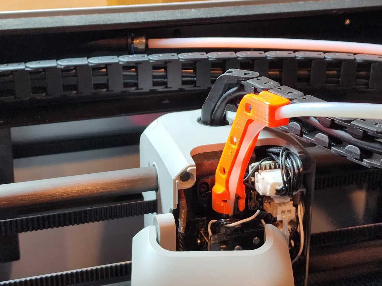
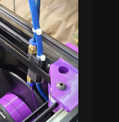
@azab2c I modified the idea of @niget2002 's bowden holder and added a second hole for my CAN cable so it was a bundle. I felt it gave the cable a little more structure and took strain off the connector (had issues with this pins).
I like where you are going with the elbow to guide the tube flatter in the enclosure though!
Awesome, was wondering about something along these lines today since I have wiring for smart runout sensor around there too. Will share details on runout sensor if/when I get it working.
Was chatting with Barry at RMRRF, I shared concerns about my ability to neatly weld polycarbonate panels into a lid. He suggested considering fallback option of using Alu L brackets to hold LID panels together, that would be neat and very doable.
That fallback option would also create a place/space to run LED strip lighting above the tool head, pointed towards the bed. Casting shadows on the part, which might cause shadows/problems with AI/ML based fluff-up detection if/when that gets added.
So, will likely place lighting somewhere optimized for the camera and viewing from the front.
Am still deliberating, procrastinating and navel gazing on this one…
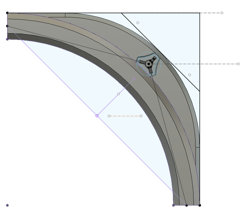
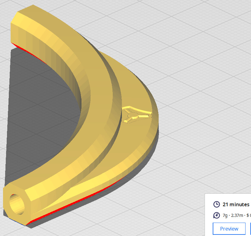
I like this, hoping to get something like this working too. Then, maybe, eventually, mod the Back Corner Right part to have wiring and PTFE guide features integrated? Am thinking the elbow guide might move better, and be neater too.
If there is enough room in the part I don’t see why that would not work! I just pulled it up and it would totally work. Curious @vicious1 what is the zip tie channel for?
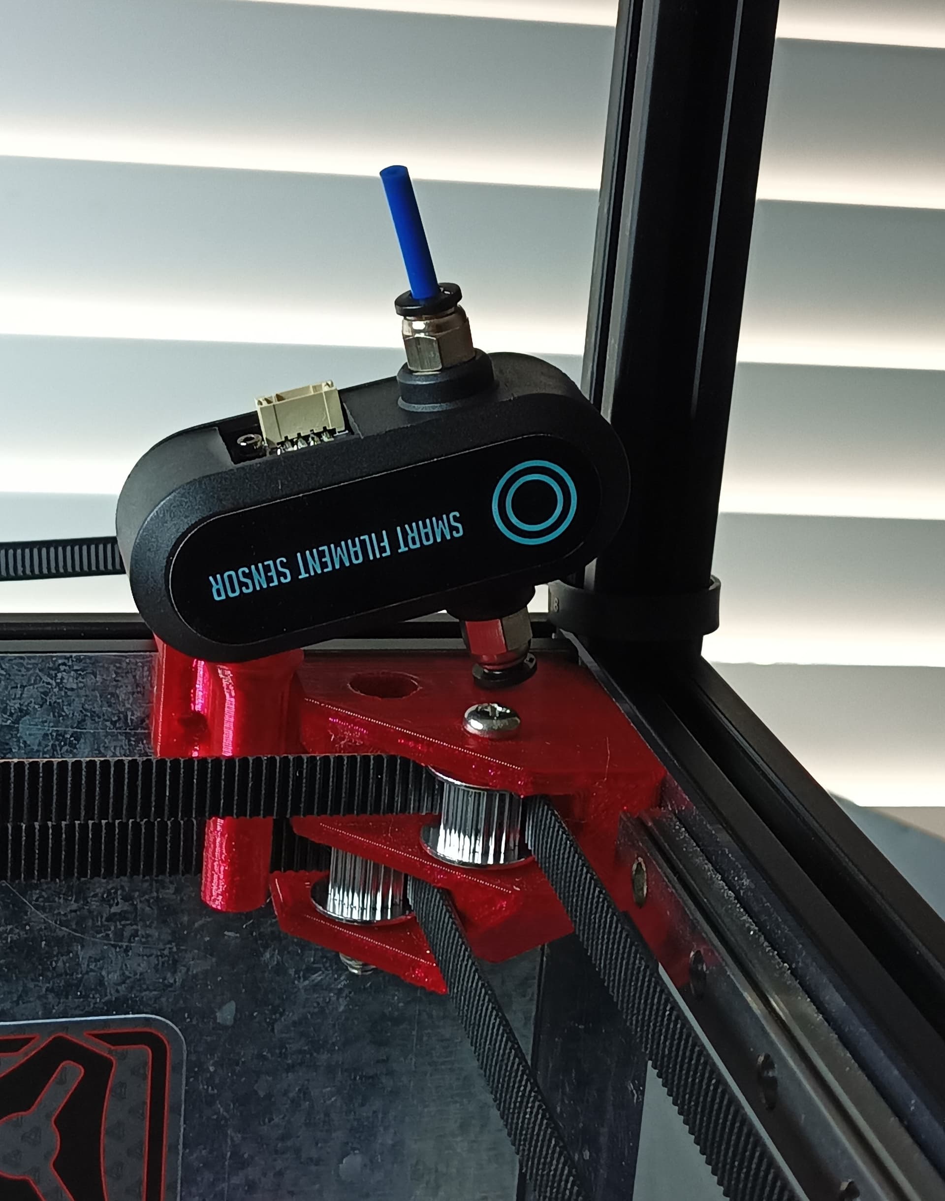
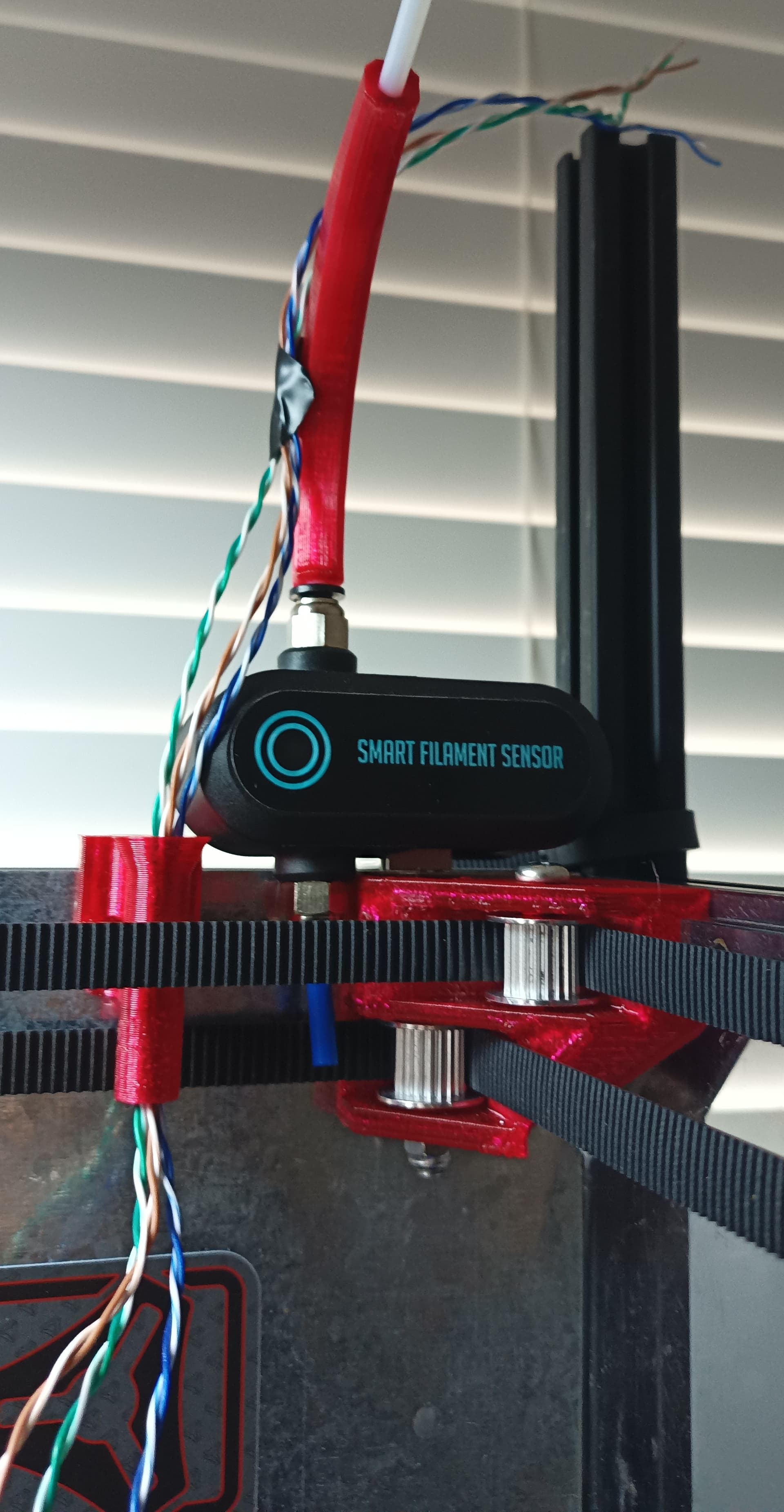
Am currently using a motion based filament sensor. It’s pretty hefty and chonky, limiting layout options. This is partly why I didn’t try modding rear right corner yet. Would happily swap sensor for something functionally same/better but cheaper. Having solid panels on frame interior is restricting my options as well .
Partly refrained from attaching anything to Rear Right Corner part to avoid wiring/filament motion from contributing to belt vibrations, no idea if that’s a valid concern?
I think you will have a hard time getting cheaper than that sensor.
I expect that you will not see any issues with vibration transfer from filament movement. That part is bolted to two opposing plans and with panels for rigidity I cant see how it would make a difference.
I do like this idea though. If the right rear mount could have a mount for the sensor that would be ideal!