Oh interesting! I would say definitely post them or send them to me, but at this point I have decided I am going to convert the one I have to the new V4 and reuse all of the electronics and such. I am not ready to convert quite yet, but it will be happening. If Ryan, never came out with this new version I would definitely want to switch the linear rail X-axis like you’ve done.
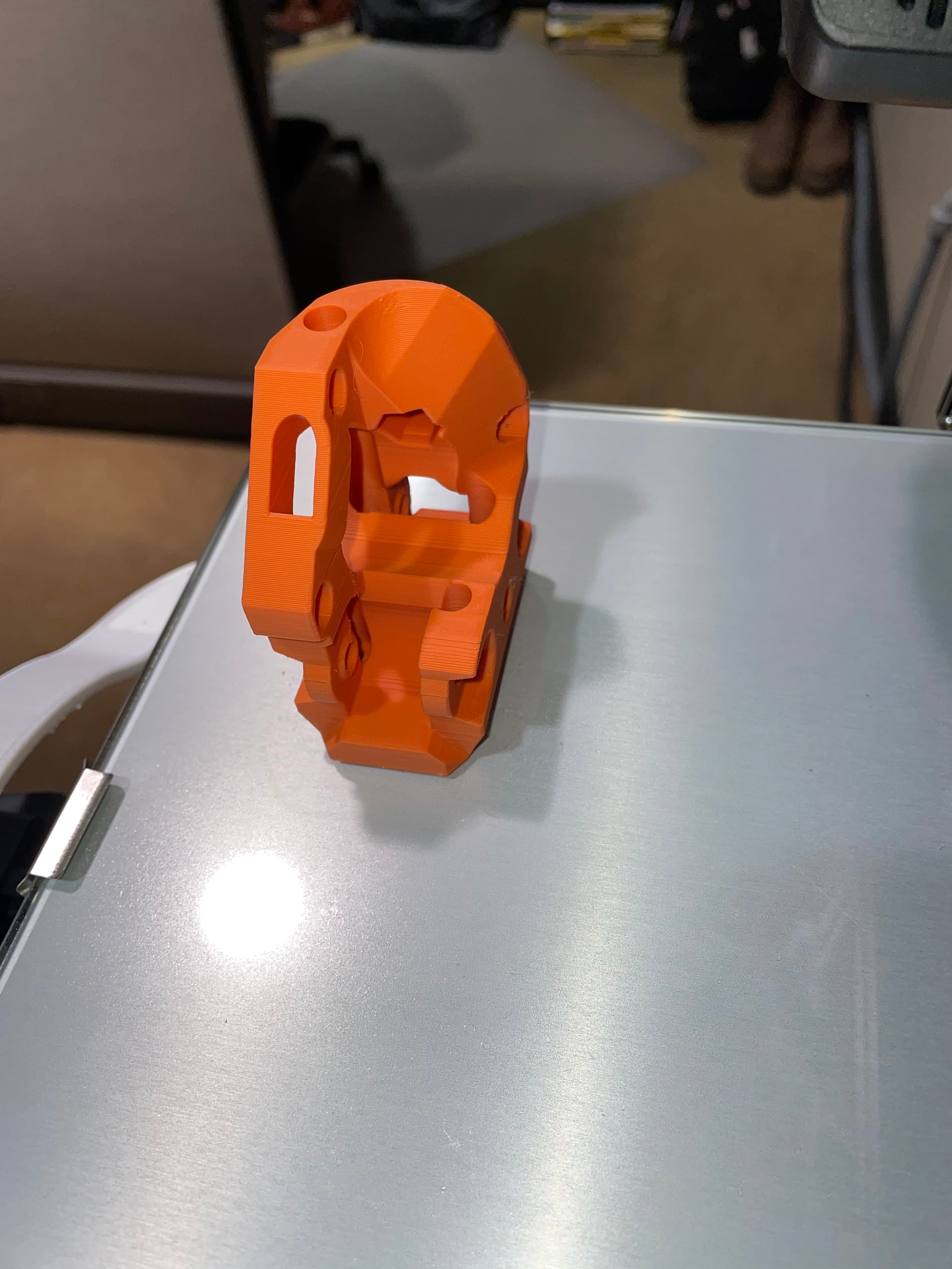
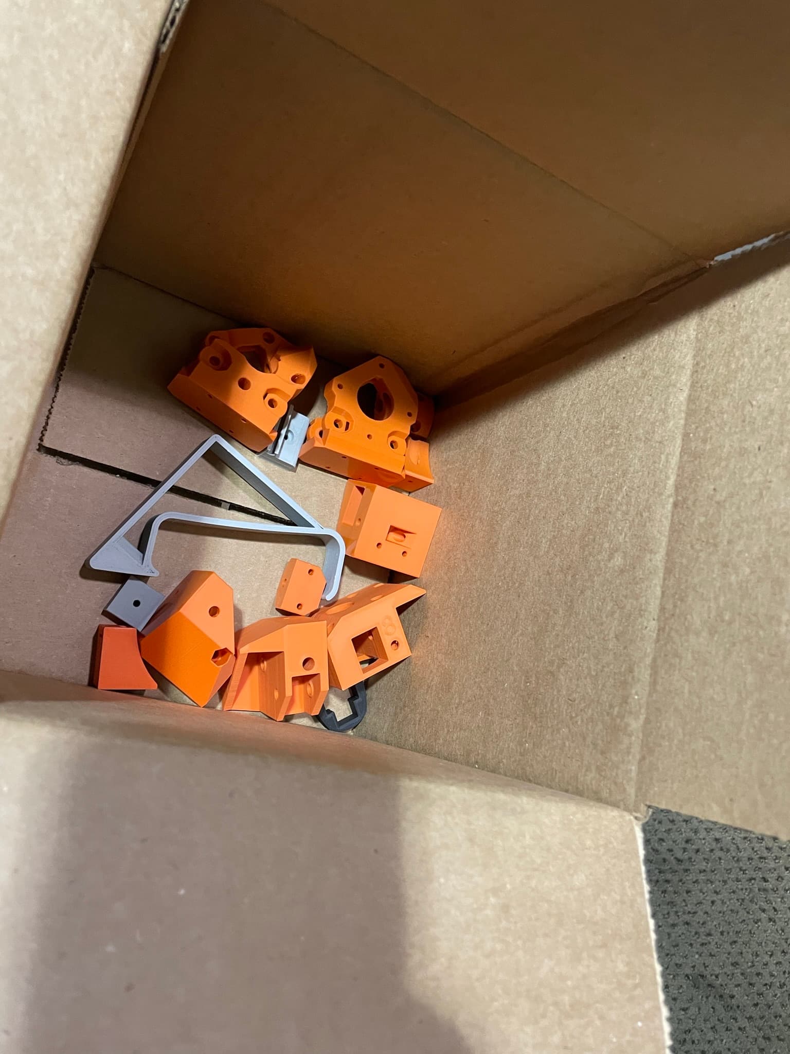
Somehow, some way, I accidently printed most of the parts for the V4 Repeat. And aluminum extrusions just randomly showed up at my doorstep the other day, not sure how that happened…
Guess i’ll just have to go ahead and get started on upgrading my printer soon…
6 Likes
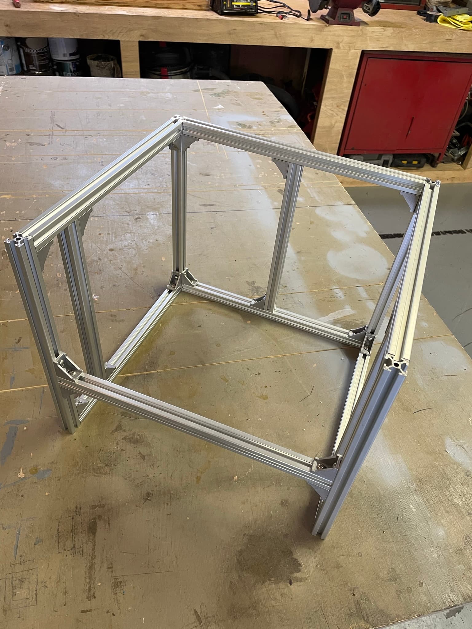
Frame is done. The kit of aluminum extrusions with the brackets came with only M5 T-Nuts for the extrusions so I wasn’t able to start mounting the parts yet unfortunately. M3 nuts have been ordered.
A couple general questions:
- When disassembling my original Repeat, I lost some bearings when taking apart the linear rails. Those things come out so easily. Does anyone know where I can just order a pack of those little bearings or do I need to buy another linear rail to replace it all together?
- Another goal of mine with this printer is reducing the noise. Has anyone replaced the heatsink/motor fan on the Hemera extruder with a Noctua fan or some other low noise fan? Is a Noctua fan adequate? I will probably put a Noctua in the PSU as well.
- Will my belt lengths from the original Repeat be the right length to reuse on the V4, or should I purchase a new roll of belt?
1-The little balls can be purchased but you need to measure exactly what you have first. They are not standard. You can run just fine with quite a few missing. Or pop on out of each that you have until they are all missing equal amounts.
2-I have not tried that. I’m out in the garage with 8 running, I am not sure I would even notice. For me these are much less noisy than the V2’s.
3-You sure can reuse. Unless you beat your printer up they should be just fine and have extra.
- Ill measure them and may order a pack of them. You are right, they do still run pretty smooth with bearings missing so it may not be an issue.
- My V2 was built in a wooden box, so of course the noise does get amplified by the box. Building the V4 with an extrusion frame should reduce the noise. I will see how noisy it is first before changing any fans.
- My V2 wasn’t overly used so the belts are still in good shape. Good to know they are long enough.
Yeah my wood one was very loud and got amplified, the HDPE version was better for sure. The extrusion builds. None of that noise at all. You can put sides on it to make it less noisy, around here I can get the noise dampening board at the hardware store, but it isn’t needed.
1 Like
Things are coming along nicely so far. One thing I am not sure how to adjust is the squareness of the x-axis (gantry) rail to the frame. I have the frame almost perfectly square. But when I measured from the gantry rail by the left truck to the front of the frame and from the gantry rail near the right truck to the front of the frame I notice that there is almost an 1/8" difference. Maybe a picture of what I am talking about would help… I will have to get a picture of it soon.
3 Likes
So for me. The back plate is the reference, and it HAS to match your calculated values most importantly for the X width so the X linear rail fits. That back plate is the most important and should be the most perfect thing you can get, make sure the diagonals are square.
Then center the Z rail in that back plate.
From there each side gets added, check the diagonals and make sure they match. For me this sometimes means leaving a small little gap.
Really it is a game of checking diagonals a million times. There are a lot of diagonals. Also widths need to. The back is the reference. If the back is 200 wide the front, top and bot all need to be 200.
Last is set the side Z rails in and make sure they are measured from the back plate, and top and bottom are equal.
Does that help?
What are you calling the “back plate”? The back z-axis rail?
Also, my diagonals on top are just about perfect. Measuring less than 1mm difference. I have not checked the diagonals across the two sides and the back, ill have to check those this weekend.
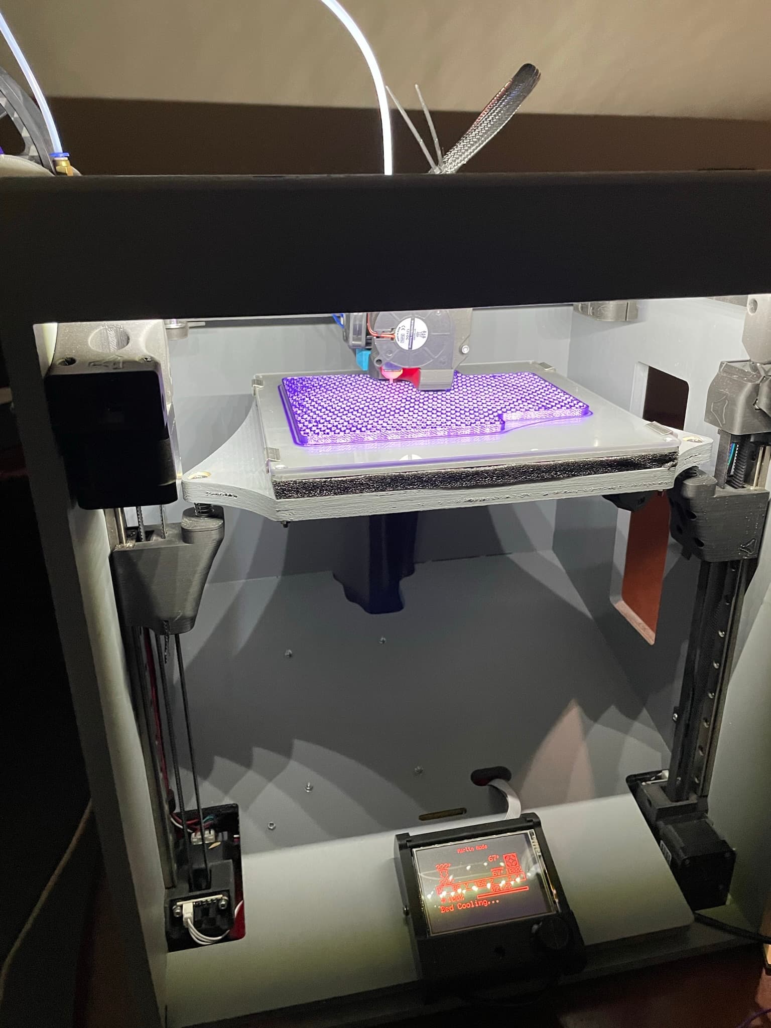
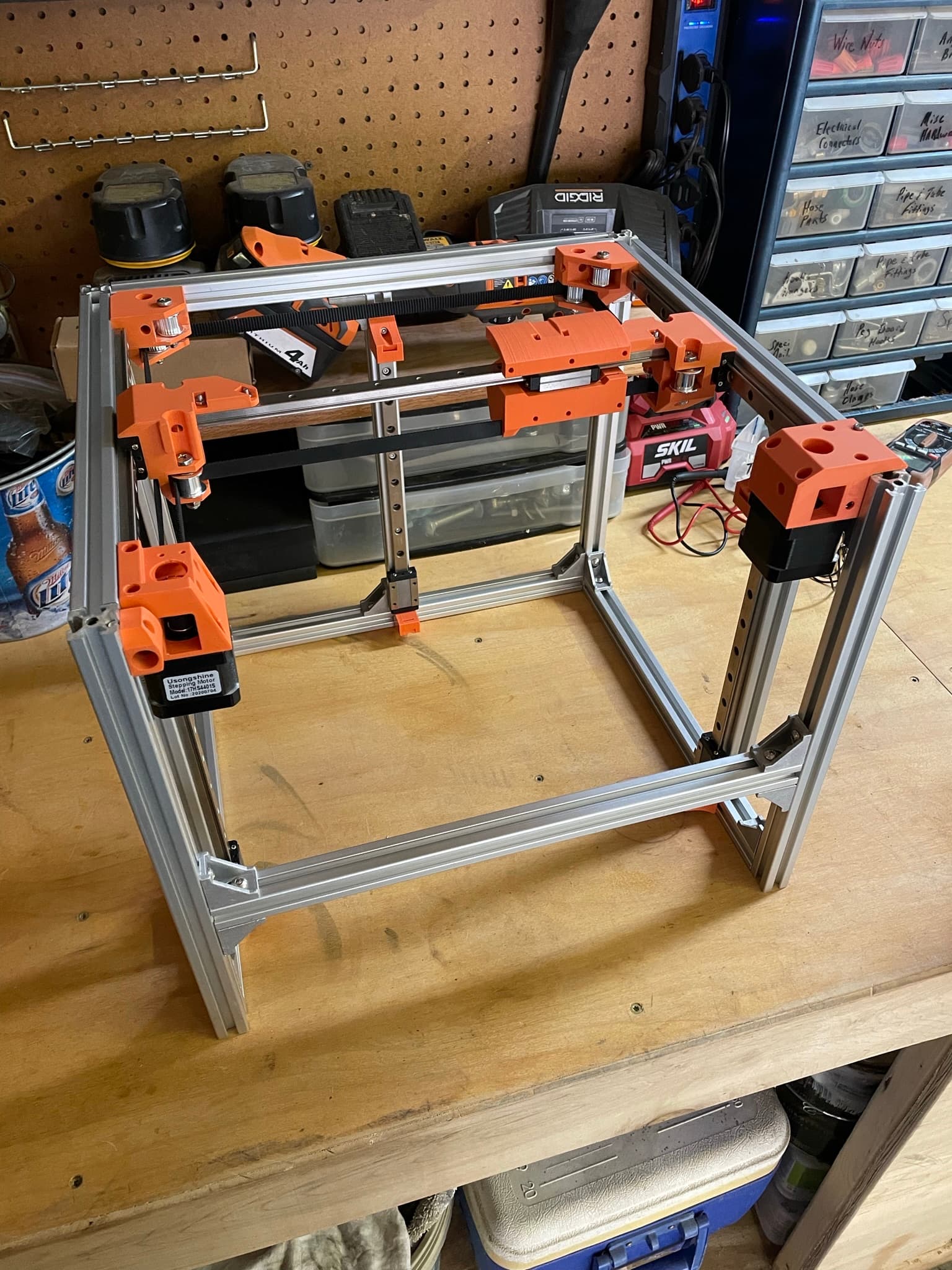
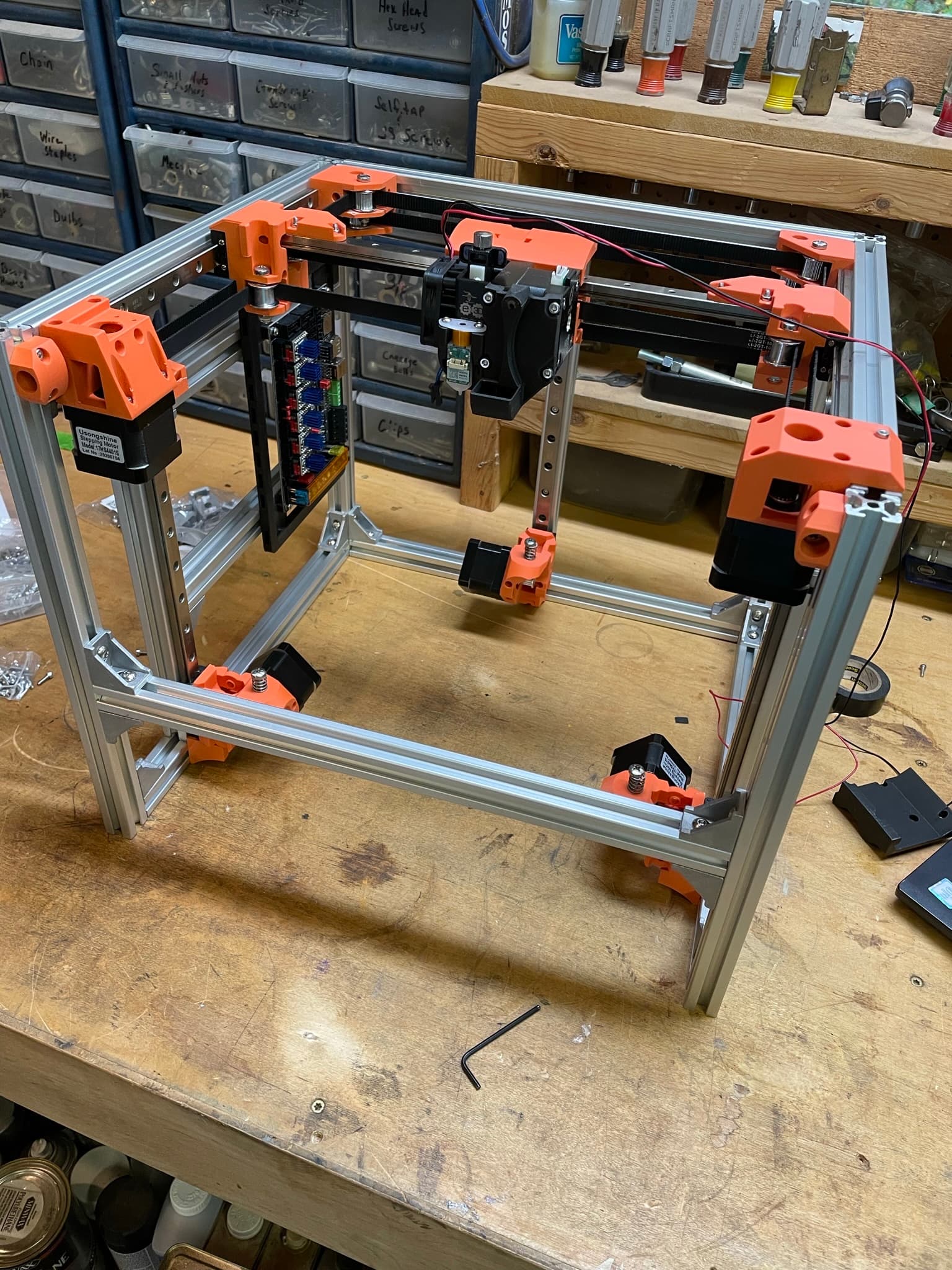
As you can see in the pictures above, everything fits together so far, including CoreXY system and all that. I need to cut a new build-plate on the CNC as well, which will tell me that my Z-Axis rails are in the correct spot. So I think I have all my extrusion lengths correct. I think I just need to play around with it to get the gantry is square to the frame. I will post pictures this weekend of what I am measuring.
1 Like
The square at the back of the printer as you look at it. The 4 extrusions that make up that square.
BAck, top bottom left right not only the diagonals, but the dims between pairs. left right, top bottom, front back.
It seems hard until you get it. On that same note. I do chase the zeros of accuracy on my printers because I print large parts that people rely on. You could slap this together, and it will print well, you could just get leaning or skewed parts, that most people do not notice.
Okay I gotcha.
I will check all these and report back. For my own mental sake, I want to be as square as I can possibly get it. I won’t be able to sleep knowing my printer is not printing square parts. Its a medical condition I think most people in this forum suffer from…
2 Likes
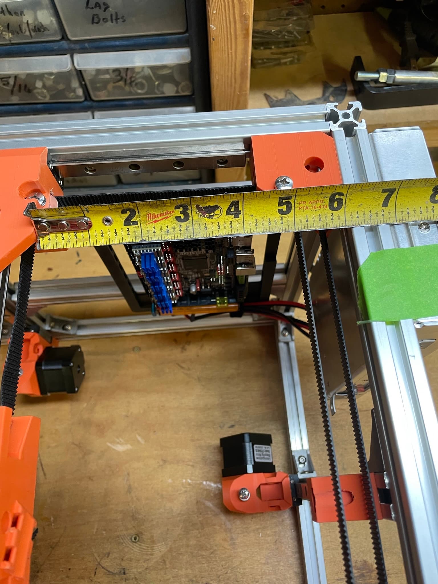
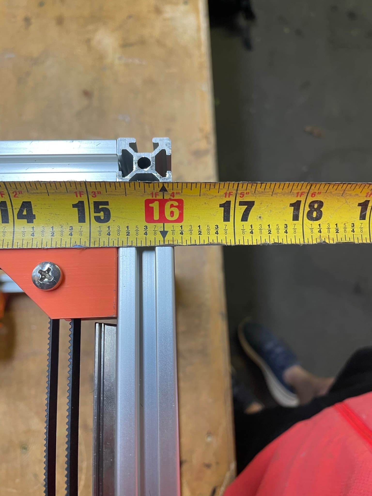
Okay so let me show you what I am working with here.
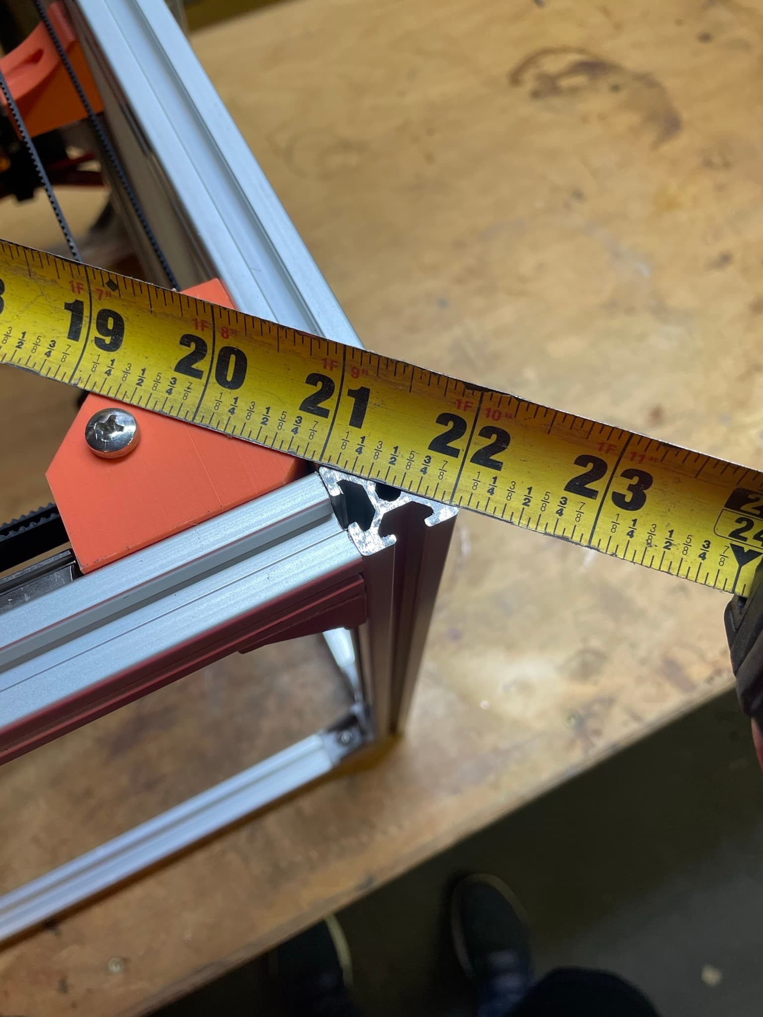
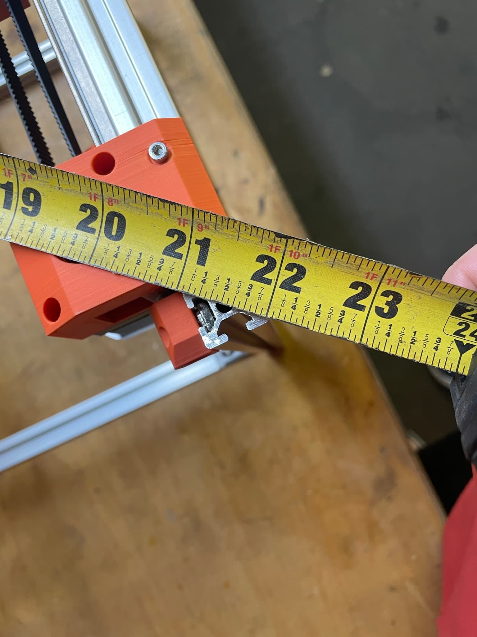
Here are the dimensions from the trucks to the back of the machine (at a random position). You can see there is a concerning 1/8" difference between either side.
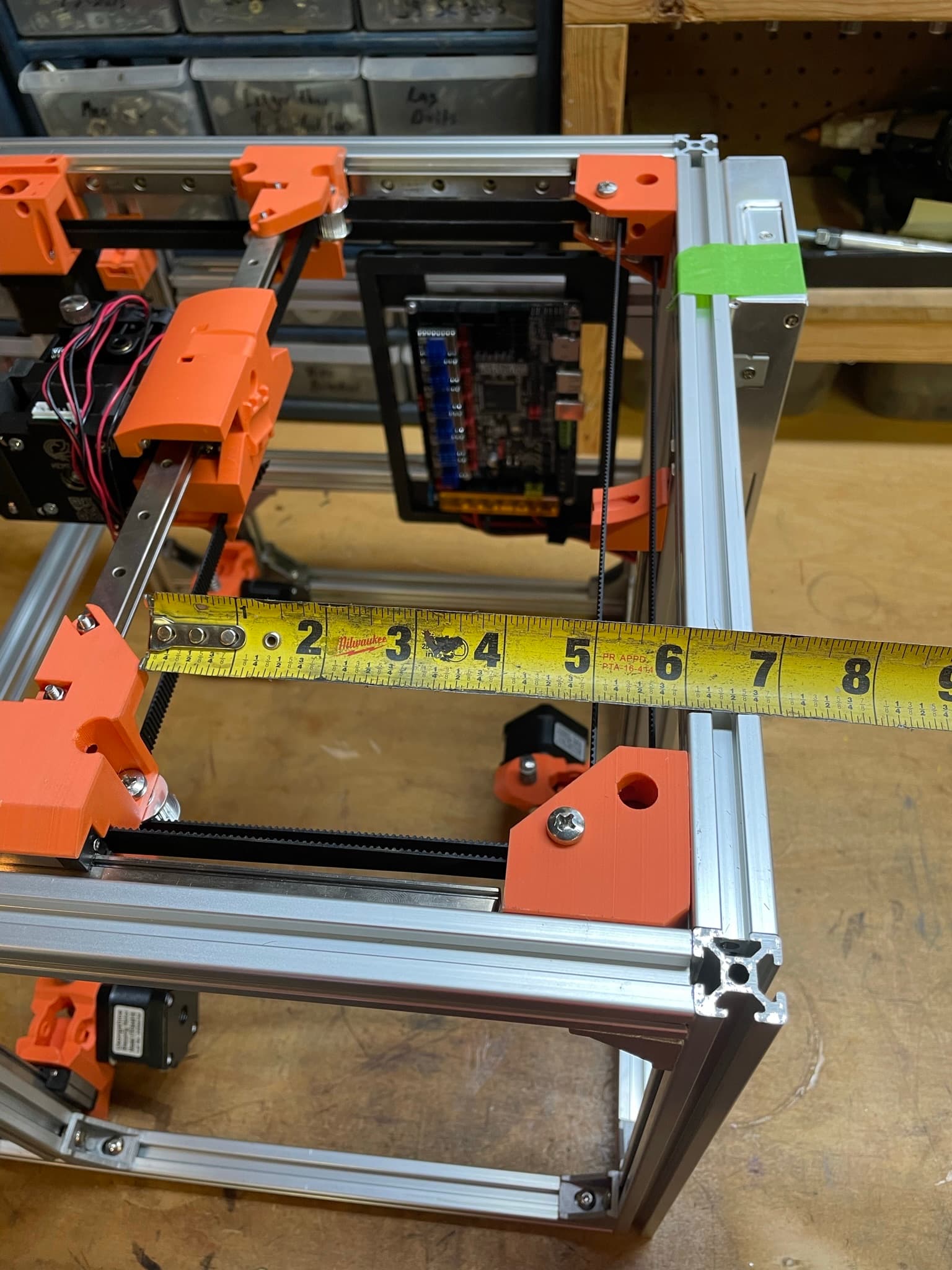
But here are the diagonals of the top. They are about 1/16" difference. I think thats pretty good, right?
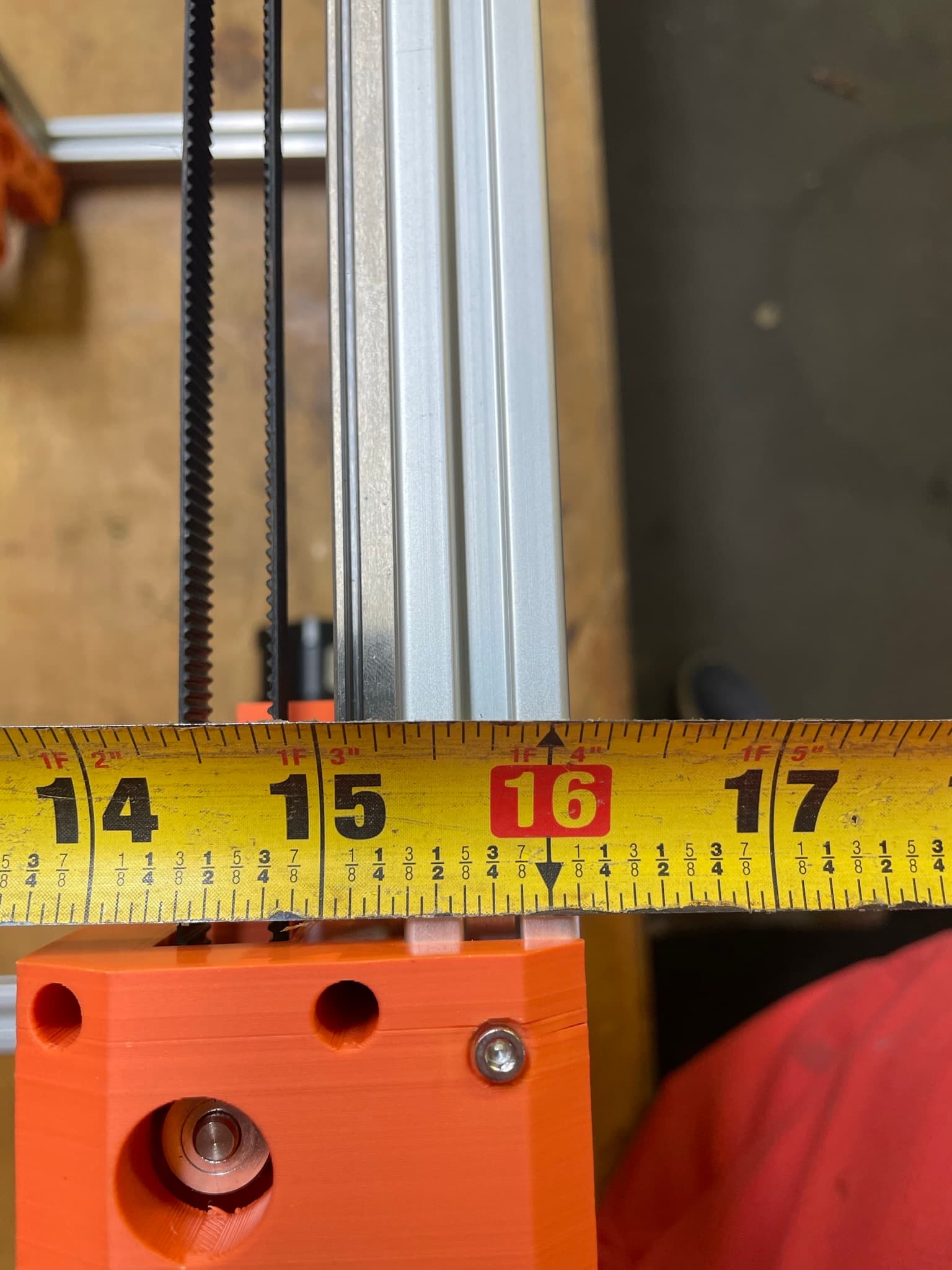
Also, here are the dimensions from left to right on the top of the machine to make sure I have equal length sides and not just worried about diagonals. These are pretty much dead on.
So, why do you think the x rail is out of square with the frame? Anything else I should check and verify?
Personally, I’d say you need a new tape measure. But that’s me, and I should not be listened to under any circumstances…
Have you measured the trucks themselves? Is there 1/8" variation between printing variation, mounting variation, and belt stretch? You are assuming 100% absolute identical and symmetric printing (including variation) and mounting (including variation), both to the rail and to the pulley/idlers. That’s a whole lot of absolute identical and symmetric. Not saying it isn’t so, and perhaps you printed the parts aligned in such a way as to account for possible print variation, and make them symmetrical. Are the bolt holes tight enough to ensure that there’s no play before you snug them up? Honestly, I don’t know, I don’t have a MP3DP Repeat.
Now, that all sounds like I’m pushing back on you and questioning your abilities and skills. I’m really not, I’m just pointing out other potential points of inconsistency that I can see, that weren’t immediately obvious, and that didn’t appear to be addressed. Another question, is that 1/8" error consistent across the full Y-axis travel? Does it get worse further away from the back plane? If not, where does it get out of square? Is it out of square when fully zeroed/maxxed out to the back of the machine?
1 Like
The back of the trucks that I am measuring off of are indeed co-planer. So I am measuring from the same plane on the X-axis on either side. So that I did check.
Now this is something I probably should have checked, but I haven’t yet. I have found that no matter where I move the Y-axis, the 1/8" stays pretty constant. What I haven’t done is push the axis to it’s max and min. This would be a good test, and may even fix the issue if I push them both to their zero points. I will have to report back on this one.
Okay so now that your frame is square the belt tension is what squares the X rail.
Pull on one of the belts going across the back, watch the sides of the X rail, one will move towards the back.
To set the X rail I move it all the way to the corner blocks and you can see how crooked it is. Loosen the linear rails 4 screws a bit so it can move and tighten and loosen the AB belts until it is straight. Make sure the A block is always forth out front so it can trigger the switch before it runs into the B block when homing.
Snug up the rail and then you can dial this in to any degree of perfection you need with a real print. I print the temporary LR3 struts and measure the diagonals of the print. Then make tiny 1/4 tension adjustments to the belt.
PS you are into territory most printers can not and do not really ever adjust. I love this part because we can get some stupid accurate prints now.
After you get it printing a nice square on the XY plane, there is one more test to do.
Got it. Thanks for the instructions! I will do this and tune it up.
Once i’ve got the XY squared up, ill be ready for the next test.
1 Like
I’m learning a lot. Probably use this thread to write up some instructions.
100%. My corexy is the same way. I pulled the gantry against a hard stop, near the motors and then tightened the belts (my printer moves the motors in their mount) until both sides were tight and just touching the hard stops.
Very surprising, honestly. That the belts do that.
1 Like