Hmmm. I can’t quite figure this out. I need to move the left truck towards the back by ~1/8". I have loosened the 4 rail bolts (2 on each truck). I can pull the top belt in the back and it moves the left truck just how I need. But I am not sure if tightening either belt tensioner does anything for me. I have tried tightening and loosening both belt tensioners and neither of them seem to move the trucks in either direction.
I think I have it square enough now. It is quite difficult to get perfect. I ran out of tightening room in the tensioner, so I had to unhook the belts from the gantry and try to get some extra tension in the initial install of the belts. Its just a pain trying to get a the “locking” small piece of belt in behind the belt where it sits in the gantry.
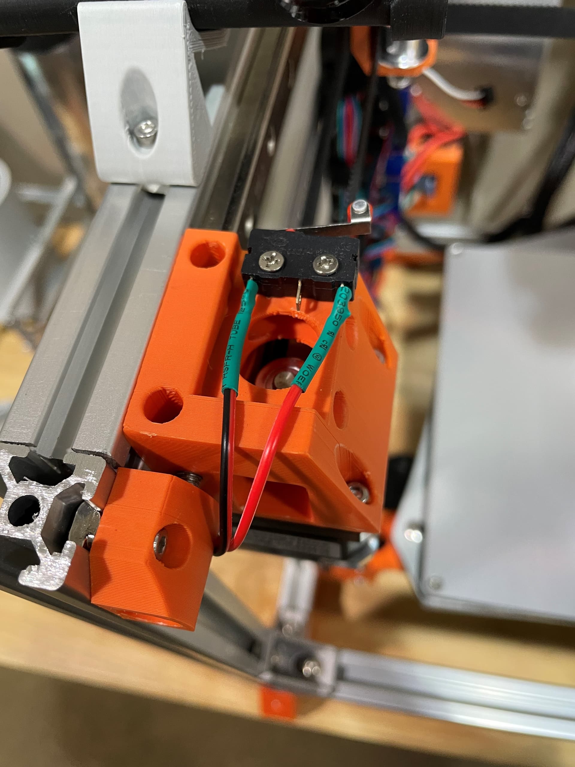
Another question, is this machine using optical or switch endstops?
Yea, belt tension will affect squareness on a corexy. The way we do it on the railcore is clamp the moving rail against a side with a couple 123 blocks in between. The forces it square to the frame. Then tighten the belts so they’re the same frequency when you strum them. Doesn’t matter what frequency as long as they’re the same, and tight enough to not slip of course.
Needle nosed pliers help with that locking piece. As Barry said snug but not crazy tight. Don’t worry about it too much after you run it a bit test prints make it pretty easy to sort out later. It gets down to 1/4 - 1/2 half turns on the tension screw can get you ±0.2mm across 150mm diagonals. Most people have never bothered to worry about that kind of precision.
Try to enjoy learning about it, if it stops being fun, move on to the next step.
Can someone confirm what pins the endstops should go to. Of course X-min and Y-min. But does the NO pin go to the signal and COM go to GND? I am not supposed to use the 3.3v pin in the endstop header right?
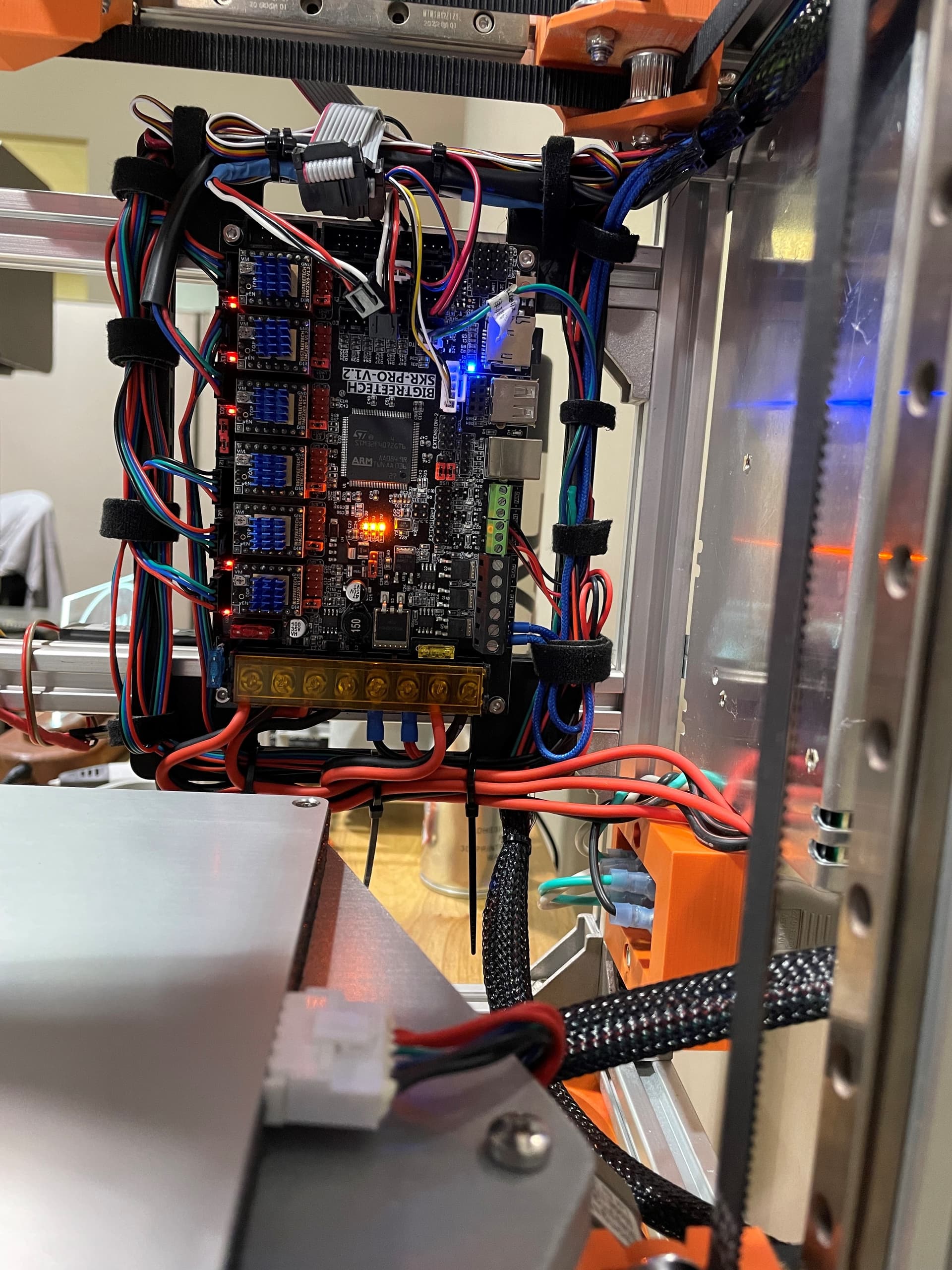
I just finished up the wiring and went to turn it on with the SD card in it with the new firmware. I am getting these 2 lights and nothing else happening. I noticed my endstops where opposite somehow, so one of them is clearly backwards.
So then I just tried again with neither endstop plugged in and I am now getting three orange lights and one blue and the stepper lights are coming on. But I didn’t get any blinking. Isn’t it supposed to blink when it flashes?
The endstop is only two wires. But I used a plug that has three wires in it and just left the white wire unused. I guess I could have taken the white wire out of the connector so it’s not confusing. But I have black to GND and red to NO.
Since my last post, I have plugged the TFT cables in and turned the printer on WITHOUT THE ENDSTOPS PLUGGED IN. Everything boots up great and I can move all axes and heat the bed and nozzle and what not. So now I just need to figure out where my endstop wiring is going wrong.
Also, I am not sure if I am still using the firmware from the previous Repeat or the new V4 firmware I tried flashing. I don’t believe it ever flashed. The bottom of the LCD main page says “V1 3DP Repeat 513P Re.”. How can I confirm if the new firmware ever flashed?
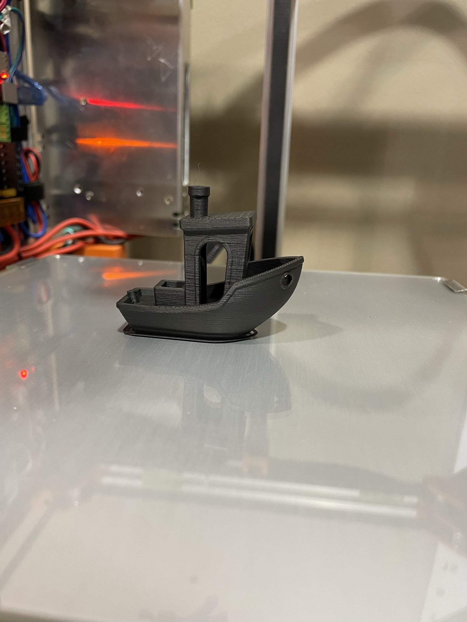
Well I guess YouTube automatically makes short videos into a Youtube Short. And I am not sure why the quality is so horrible when uploaded. Anyway, here it is printing a benchy. Its working great!
The next thing I want to tackle is the fan noise. As anyone put a Noctua fan or some other quiet fan on the extruder stepper? The fan in my PSU is also quite loud so I plan to replace that as well.