My understanding from Ryan / docs is: The best approach to getting proper fit on the dust shoe and the bristle clip attachment, is to print both the top (shoe) and bottom (clip that holds bristles) on the same machine, with the same filament, at the same settings, same nozzle, and same stock orientation, at approximately the same time. Different materials contract at different rates, different temps cause different contraction etc.
1 Like
If you turn that stock table around 180 degrees…
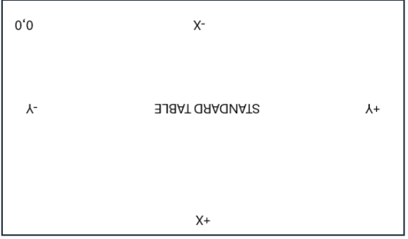
Then turn it 90 degrees more:
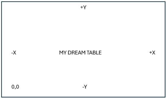
Then swap X and Y (stretch short to long and long to short)…
You get at your dream table:
It does not cause any weirdness in CAD or CAM or gcode. Works fine.
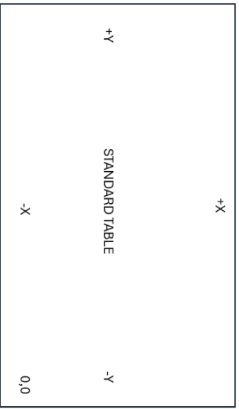
To illustrate that swapping the axes is not an abnormal CNC config, notice the similarities between this stock table:
and this table with its long and short axes swapped:
Notice the X,Y 0,0 is at the same place, and the -Y (min), +Y (max) and -X (min), +X(max) are all exactly the same. The only difference is table length (and which axes has one motor versus two motors).
I just read that this week and figured that different print runs was my problem. 2 days ago I reprinted them in the same print run. They are still loose and easily fall off. The picture shows my reprint that was all printed at the same time. Will probably try the 99.5% scaling next.
1 Like
Thanks for your first hand experience.
I know CAD / CAM works fine. It’s just how well the community supports it. If I go down the rabbit hole I’ll document it well so that it might be a config option for people down the road.
I did not read the entire thread, so sorry if I missed something……
But it sounds like you are wanting a full sheet build.
And you want to be able to load full sheets from the long side?
Am I correct in thinking that you are wanting to have an 8’ X gantry and the Y rails being the short 4’ side?
Or are you only talking about a config change so that the router still travels along the short rail, even though you want to call that Y?
1 Like
Thanks, @Michael_Melancon - it’s a crucial question.
My replies were based on the understanding that the gantry is still on the short axis, but relabeled as Y, and the long axis relabeled as X.
1 Like
I do concur with the advice to build as stock and get it working, before swapping the axes. One trick for being able to do that without having to take the core off and redo the location of the limit switch, would be to install an extra limit switch from the start, and run both wires. This gives you options for later, without tearing it down again.
1 Like
This… I’m not wanting to change the build, just the axis designation and the location of the home / 0,0 location.
Y would be 4’ of travel (formerly x) and the long mounted rail would be on the X.
The deflection of an 8’ rail would be horrendous. Not wanting anything like that.
This is indeed my intention.
2 Likes
Ok. Just making sure ![]()
1 Like
This is how I built my LR3 (w/ SKR board)
But as suggested several times above, I first built it stock (Portrait), then once I knew enough about the consequences, I modified it to Landscape.
I would have thought that you need to do both, at least that is what I did in Marlin. New X(0) motor and end stop (formerly Y(0)) moved from Y to X, New X1 motor and end stop (formerly Y(1) moved from Y1 (E0) to X1 (E0), and then Marlin configuration.h modified to redefine no Y1 and to include X1 instead.
1 Like
In FluidNC, you only have to change 2 lines.
Swap the X and Y section headers in the config.yaml file and that’s it.
3 Likes
Editing the config file is definitely the way to do it. My memory is not solid on the earlier times I did it. I may have misspoke when I said it could be done by switching wires. I cannot remember if I did wire switching. I think I did. When I did it more recently on Jackpot, I am pretty sure I did it by editing the config.
If you are confident, there us a way to have the limit switches on the “Y” axis work either direction.
This isn’t the easy way to do things, but works.
Wire the switches in series. The wire goes from the ground to the common (C) pin on one switch. Then a wire from the normally closed (NC) switch on the dame switch to the common (C) pin on the other, and finally return to the trigger pin on the control board.
By doing this, triggering either limit switch will trigger the board input. In this case you want two switches in each YZ plate, the regular one at the front, and the one in the rear wheel. By connecting them in series like this, you can switch the firmware configuration back and forth with no hardware changes required.
You should still only require the one limit switch in the core as both configurations have the same home position on the rail.
If you didn’t follow that, then just build stock for now. Honestly it’s way easier to just change how you do things in CAM.
1 Like
please post more information and pictures as to how you completed this when the time comes as I am very interested in this as well but just dont know how to go about the mounting of all of it…drag chain?? power connectors?? etc.
right now, my e-stop is pulling power from the extension cord powering the cnc but the router still is powered as the extension cord is a 3 plug retractable plugged into the ceiling. it is not elegant at all!
Technically I have built it as stock for my bootstrapped table ![]()
If I had known, I would have definitely assembled it with limit switches installed in both locations. Adding them in back shouldn’t be a problem though. There shouldn’t be much disassembly at all.
Wow, That is even easier than I was thinking. No wiring to change, just the config.yaml
100% get it. Great suggestion to have both installed and run in series.
This honestly does not seem like the big deal that people are making it out to be, but I may get bitten, and I may be humbled. Wouldn’t be the first or last time…
Your knowledge and experience is greatly appreciated.
1 Like
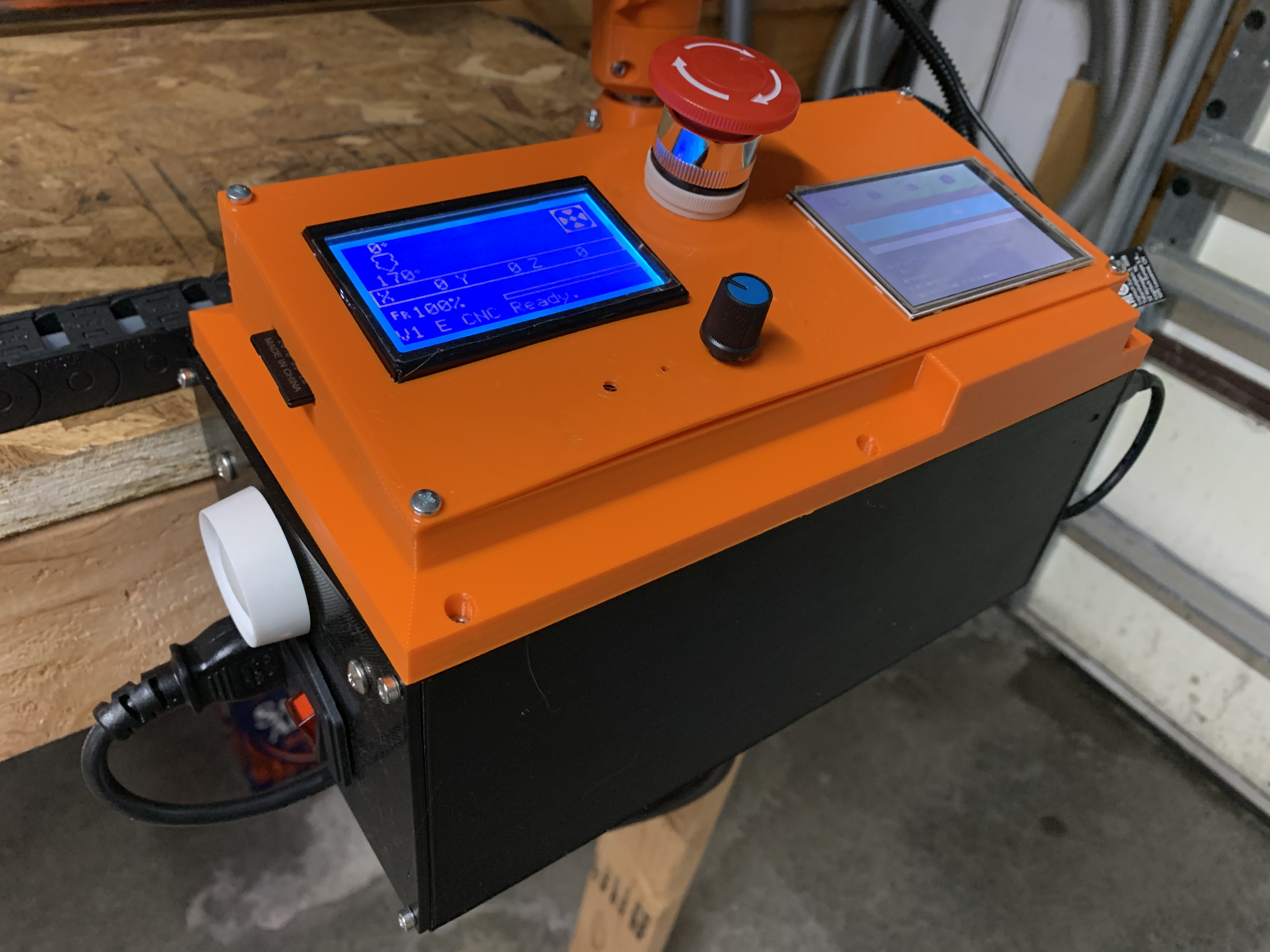
Will do. I did drag chain on my MPCNC and probably will here as well. I did a custom box on the MPCNC but I don’t think I’ll do that again with the LR since the Jackpot has the web UI
6 Likes
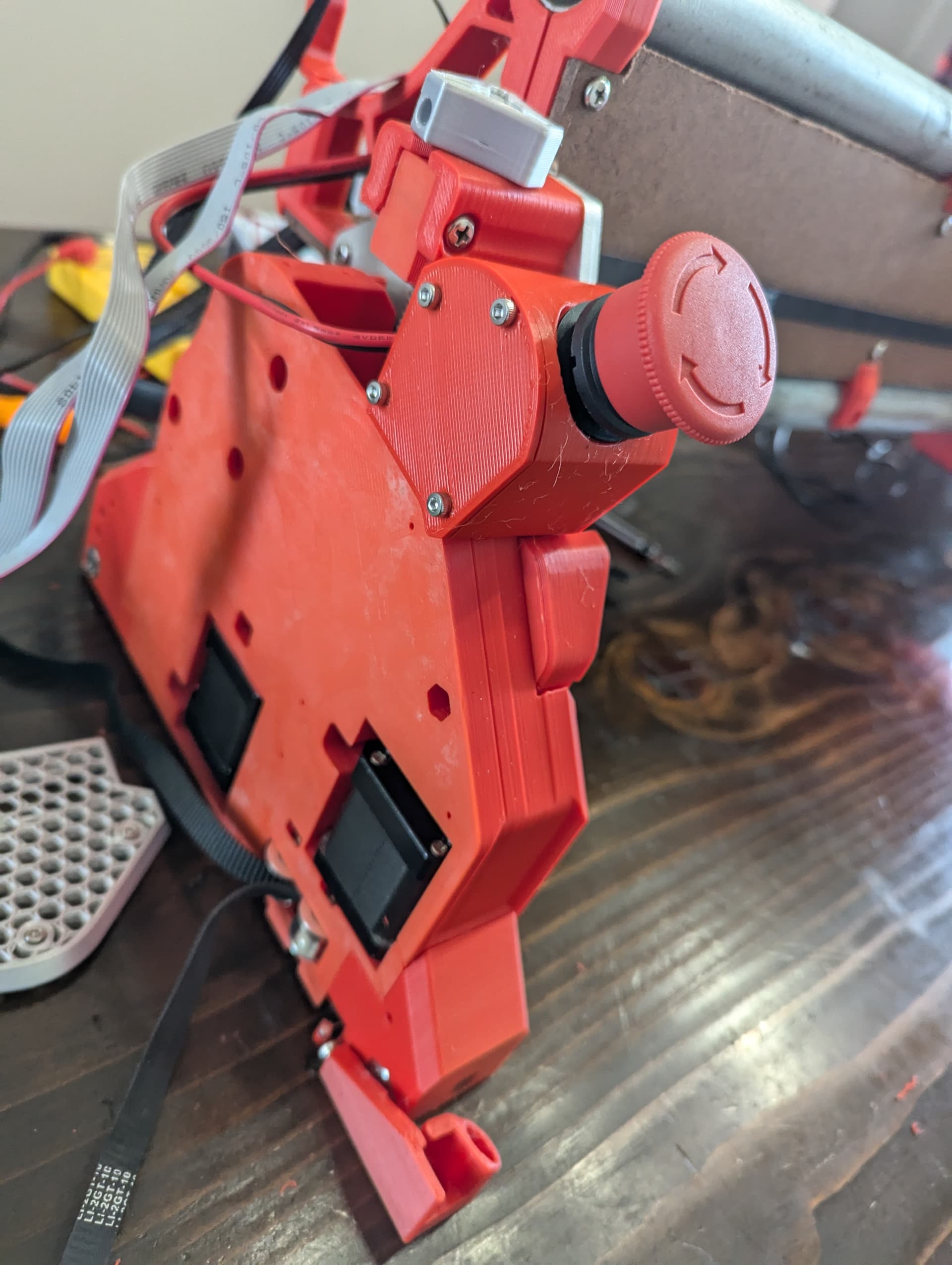
That is a nice box! On the Lowrider with everything gantry mounted i like to have an emergency power switch easily accessible and a drag chain seemed like trouble to get a switch on the table side. There is a power line to a power strip for everything. It is festooned - hanging from ceiling with the vacuum line.
I built one with the estop on the yz min plate:
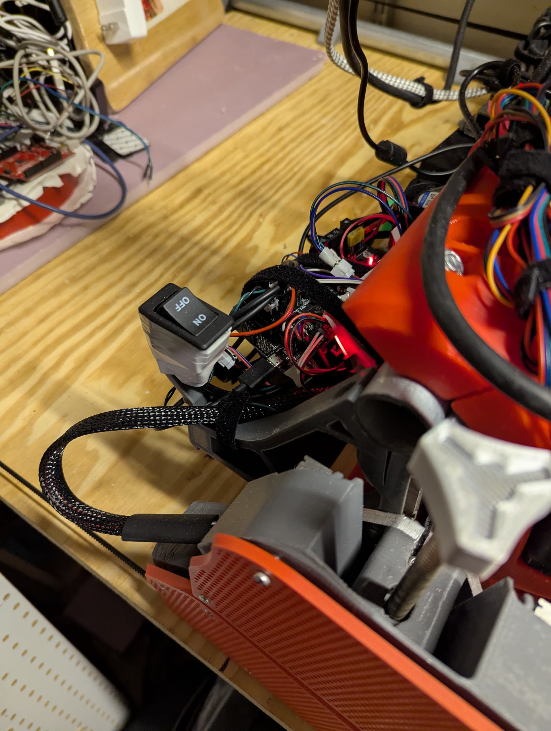
And i put a 24v power rocker on a hose retainer clip as s “temporary” accessible setup, so there are a number of ways to achieve functionality.
4 Likes
I have some updates from the last 2 weeks.
@azab2c Printing the dust shoe at 99.5% scale did the trick. It is now tight and I have 25mm and 35mm bristles on separate shoes.
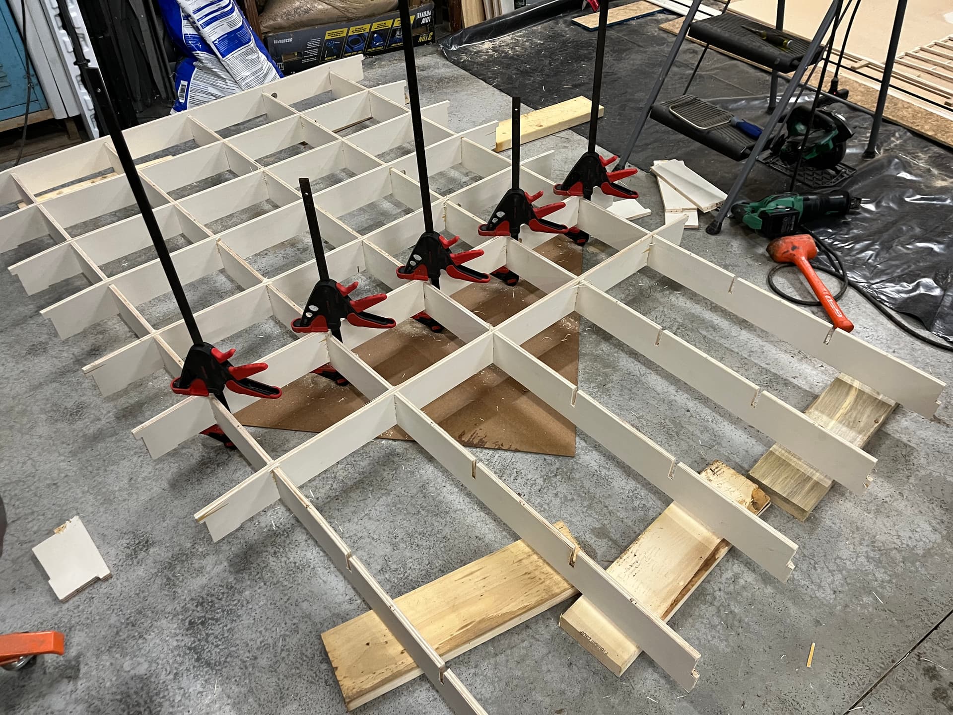
The good news is that the table build went much better using clamps to insert the X-ribs
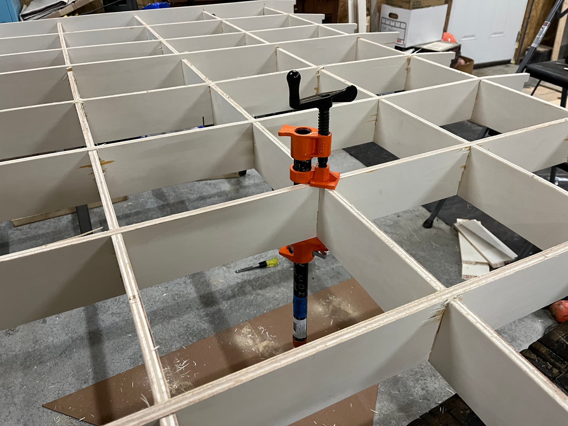
The squeeze style clamps could only generate so much force so I used a screw style pipe clamp at each intersection to get the final 1/8”

I pre-drilled and installed screws at each intersection to make sure things don’t pull apart down the road.
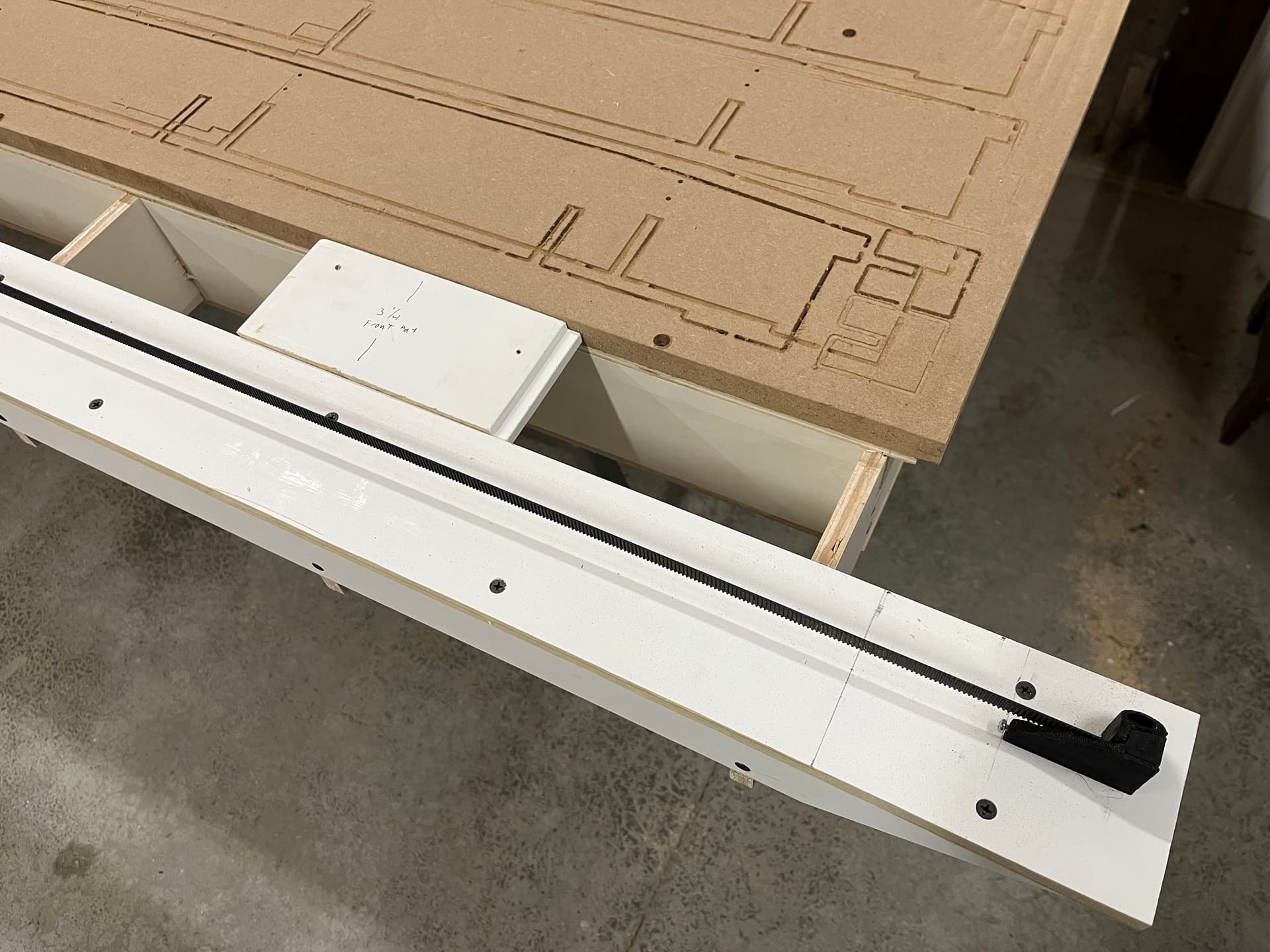
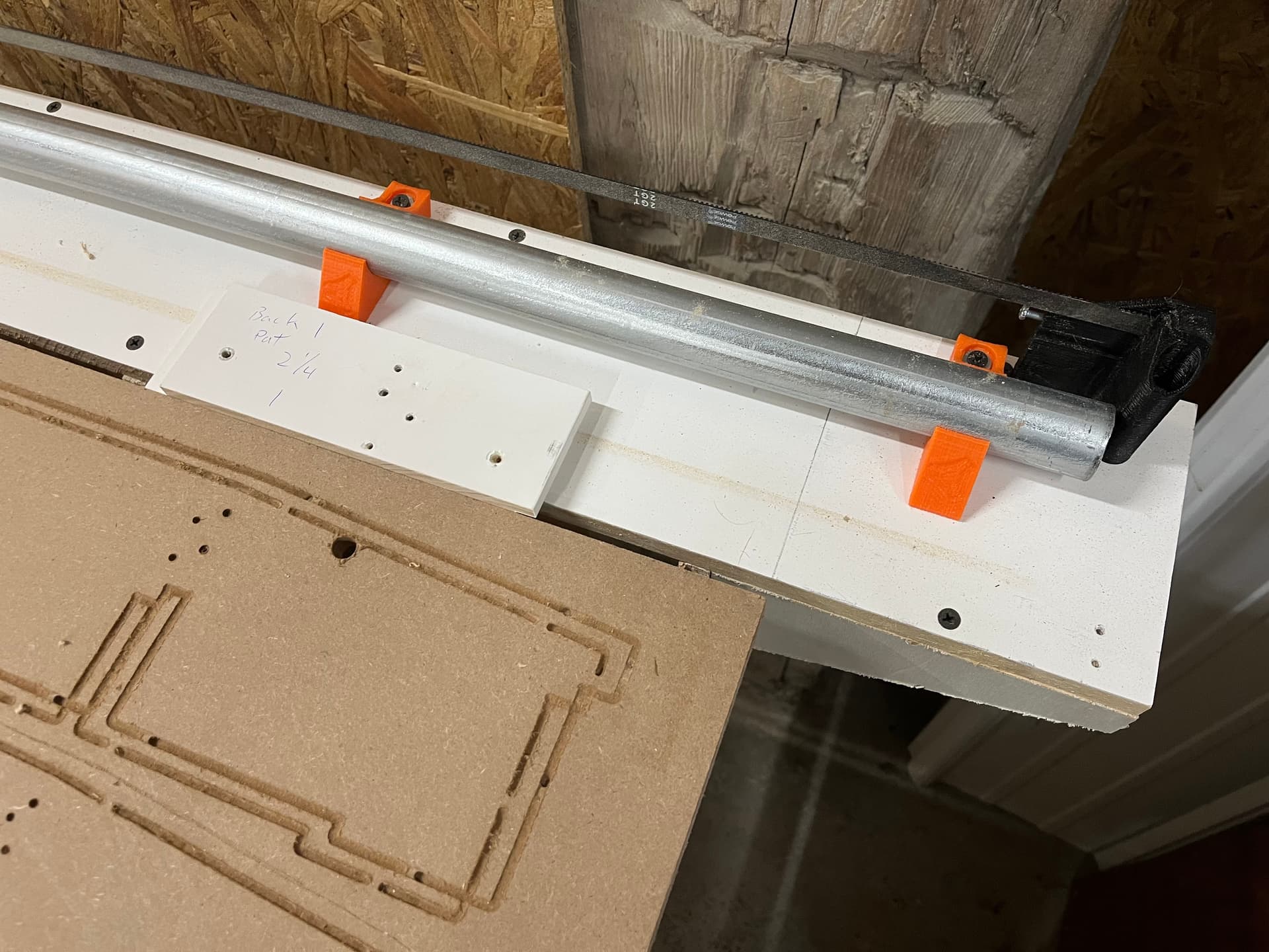
For table assembly I got the MDF spoilboard attached to the table as square as possible and then measured from the MDF using spacer jigs to make sure everything else was dead on.
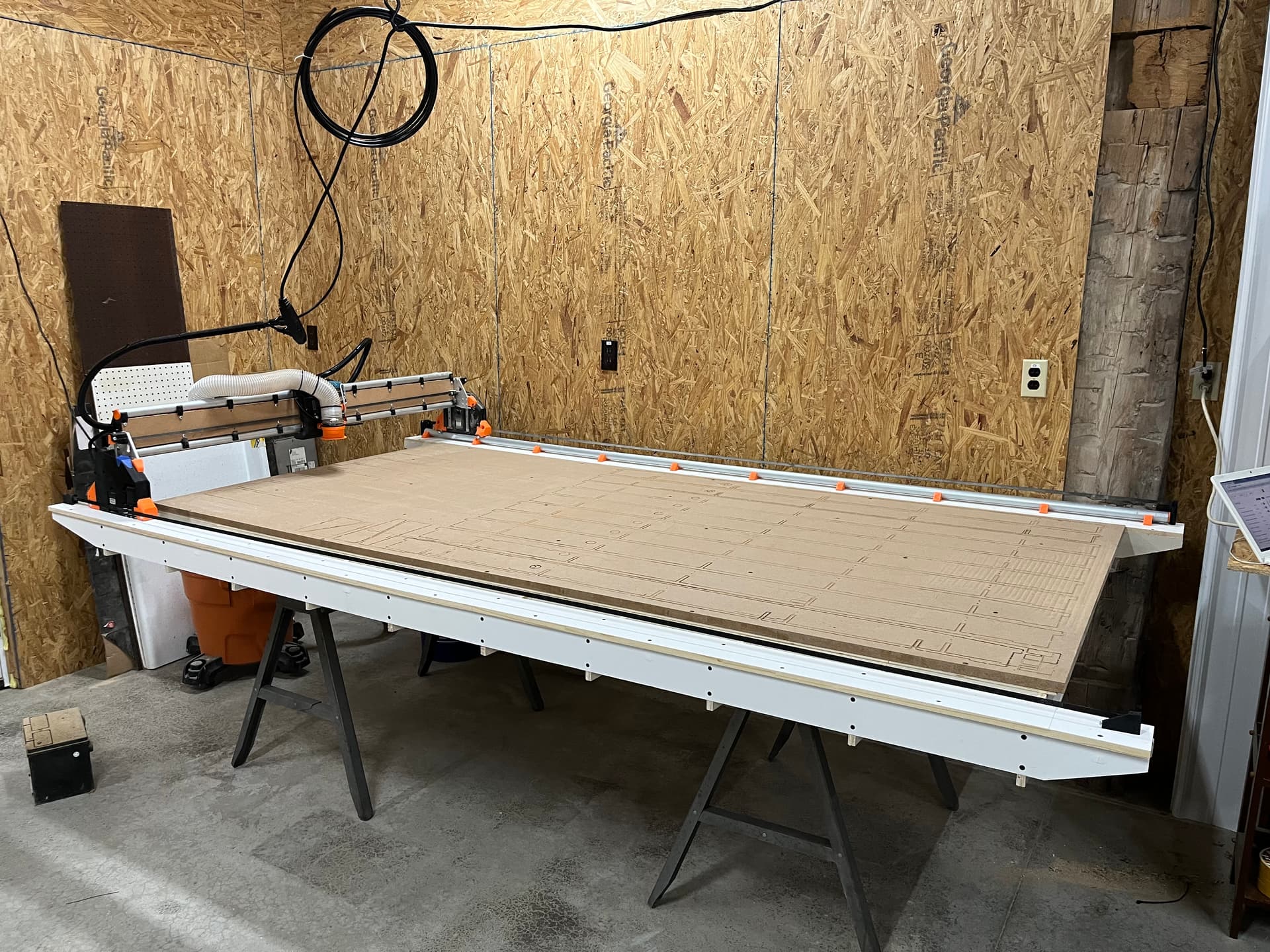
Now for the bad news on the table. As I knew, my joints were a little tight. Once i got everything together and sheeted I realized that the whole table has a bit of a smile along the Y. My recommendation to others is to make sure your slot width is dialed in. Being too tight will create a bowed table.
The good news is that the gantry rides along the smile and I only had 1mm of variance along the 8’ of Y. Whatever workpiece I lay down will just need to bend slightly with the table.
The X had about 2.5mm of variance due to a smaller smile going the 4’ direction.
To get rid of the high center along the X I started surfacing with a ½” dovetail bit. In doing the first 1mm cut I saw that the router needed to be trammed.
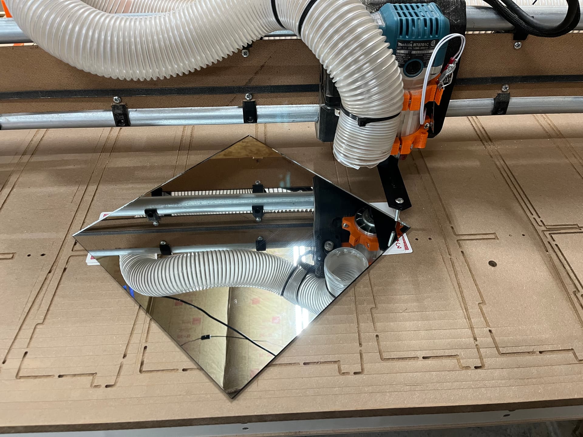
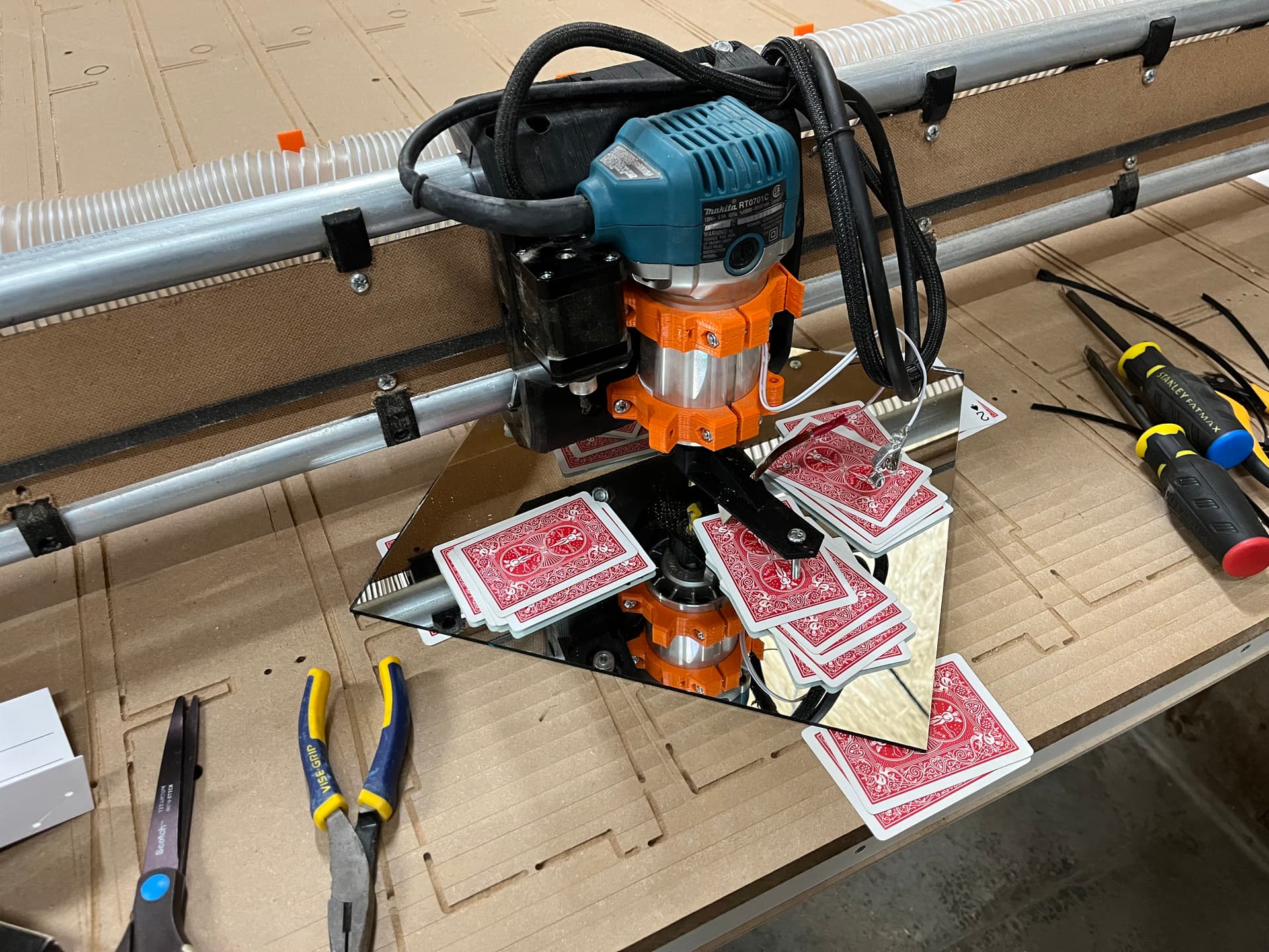
To tram I used RobP’s post as a guide. A mirror and some playing cards is all it took. I used playing cards to measure instead of using a dial indicator.
- First I printed a tramming tool for my router
- Second you grab a deck of cards and a known flat surface. I used a 12x12 mirror I had from 3D printer build surface.
- Level the mirror to the tramming tool using cards underneath the mirror. Note to keep tramming tool rotated in the same direction when leveling the 4 corners
- Center the router on the mirror and rotate the tramming tool and measure the gap between the tool and the mirror at the X and Y extents.
- For me +Y needed 3 cards, -Y needed 8, -X needed 7 and +X needed 5
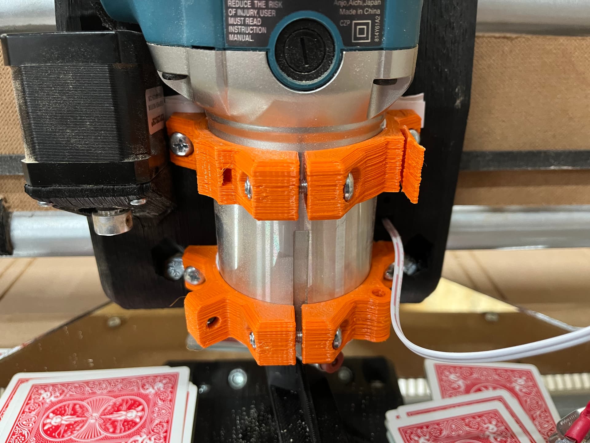
- I shimmed the top router mount forward using multiple pieces of card stock.
- I shimmed the between the router and the mount to rotate the router CCW
My plan is to do a 1.5mm rough surface and then a .5mm fine surface to get the table where it needs to be. More on that later.
I also fed an air line through to the tool head for future air blast if machining aluminum or plastics.
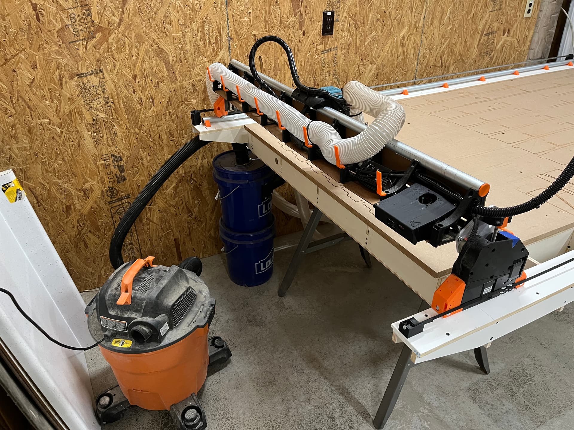
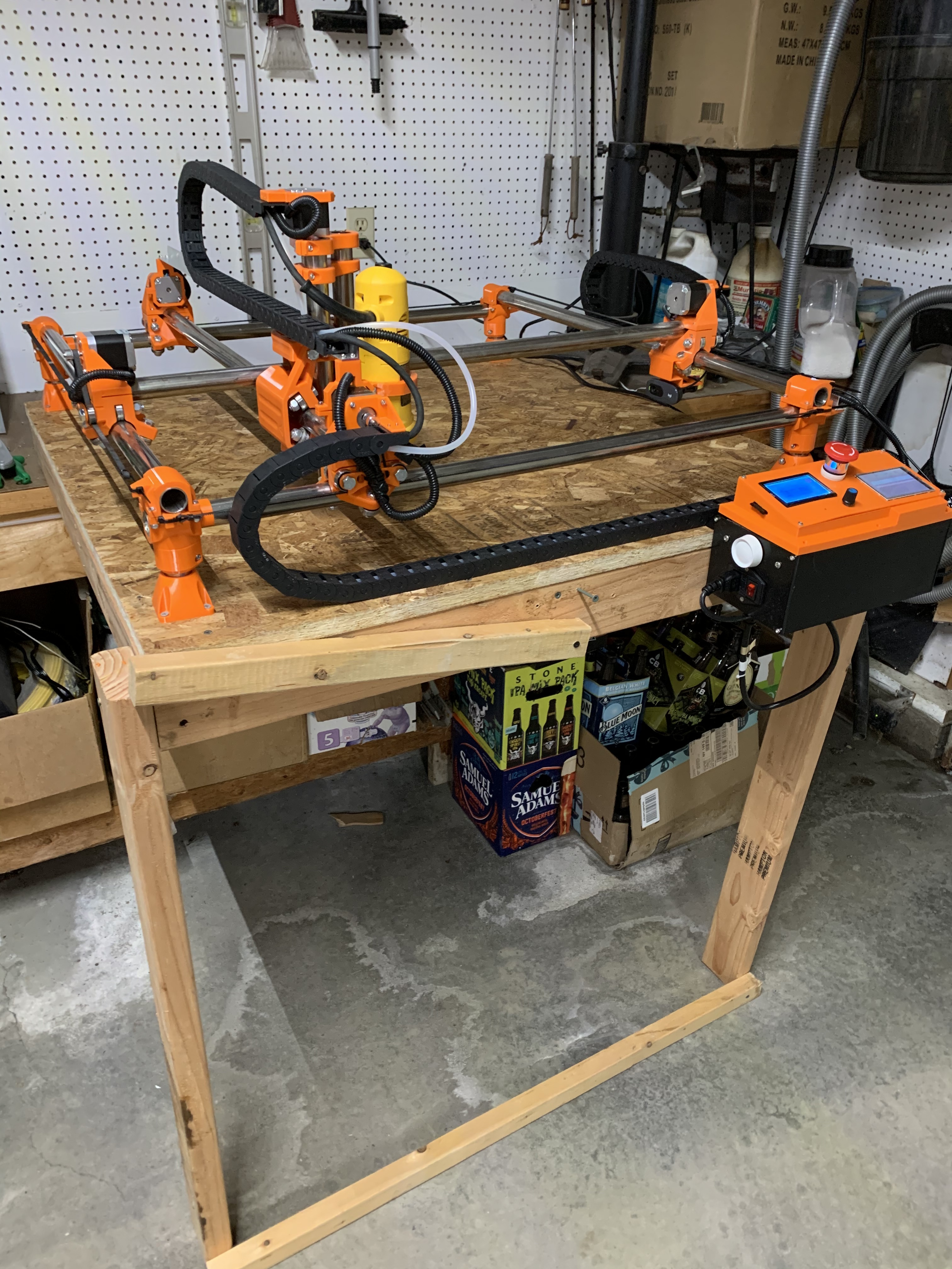
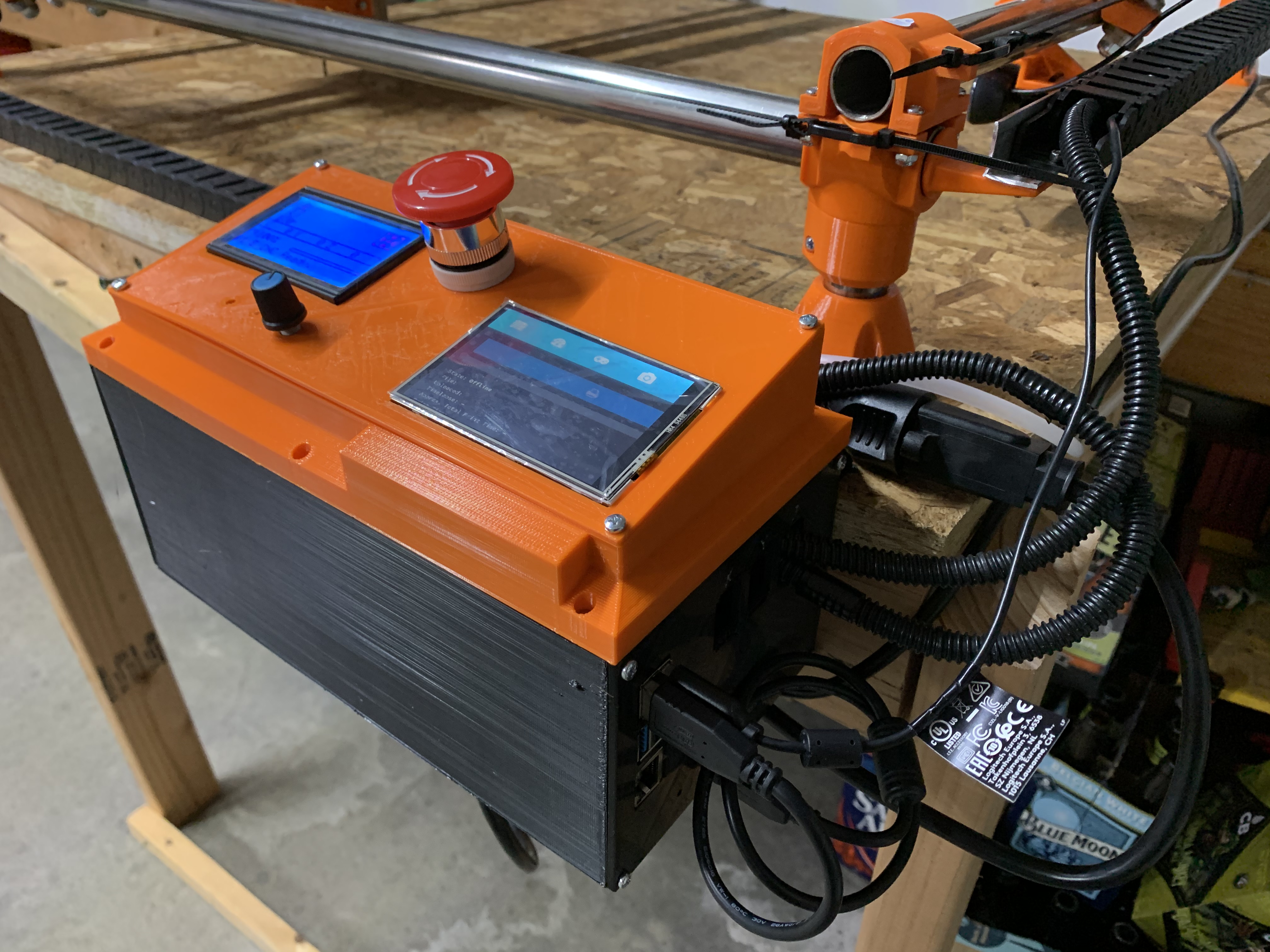
Lastly I cleaned up my electrical and mounted the jackpot control box. Here you can see my current dust collection setup. The vacuum has a filter bag in it which improves the filter life by about 1000 times.
I will probably forgo the swapping of X and Y. The worst of my table’s smile is on the +Y end. If I were to make the swap I would have to work with that issue more frequently. I still like the idea but probably won’t do it unless I build a new table that fixes my mistakes…
I am also re-thinking my electrical plans. I want to be able to easily take the gantry off the table and cable chain definitely complicates that. Taking inspiration from @orob’s pics above,I will probably make everything gantry mounted and go with the pendant over physical buttons for feed hold, start, and probe
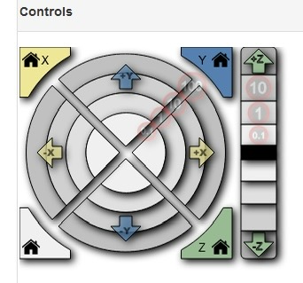
I’m not sure if I mentioned it here or not, but I had a lot of problems with the “controls” section of the FluidNC web UI not working for me. It was apparently the iPad that I was using. Now that I have the table built and I’m not on the floor, I’ve switched from the iPad to an old linux laptop. The UI seems to work fine on that.
3 Likes
Were you trying to drive it from the captcha browser? What happens if you close that and open regular safari and connect to fluidnc.local ? does it then work correctly for you?