LR4 - Black & Orange Edition

Hello Ryan and the greater V1 community,

I, like many others, am jumping on the LR4 train… I built a 24” x 24” MPCNC back in 2020 with some of the free time I had. I always had my eye on the full sheet lowrider but I’ve been busy. Somehow the LR4 release caught me at the right time. I’m still busy as ever, but I do have a little extra time around the holidays. So… the gantry was assembled over Thanksgiving break.

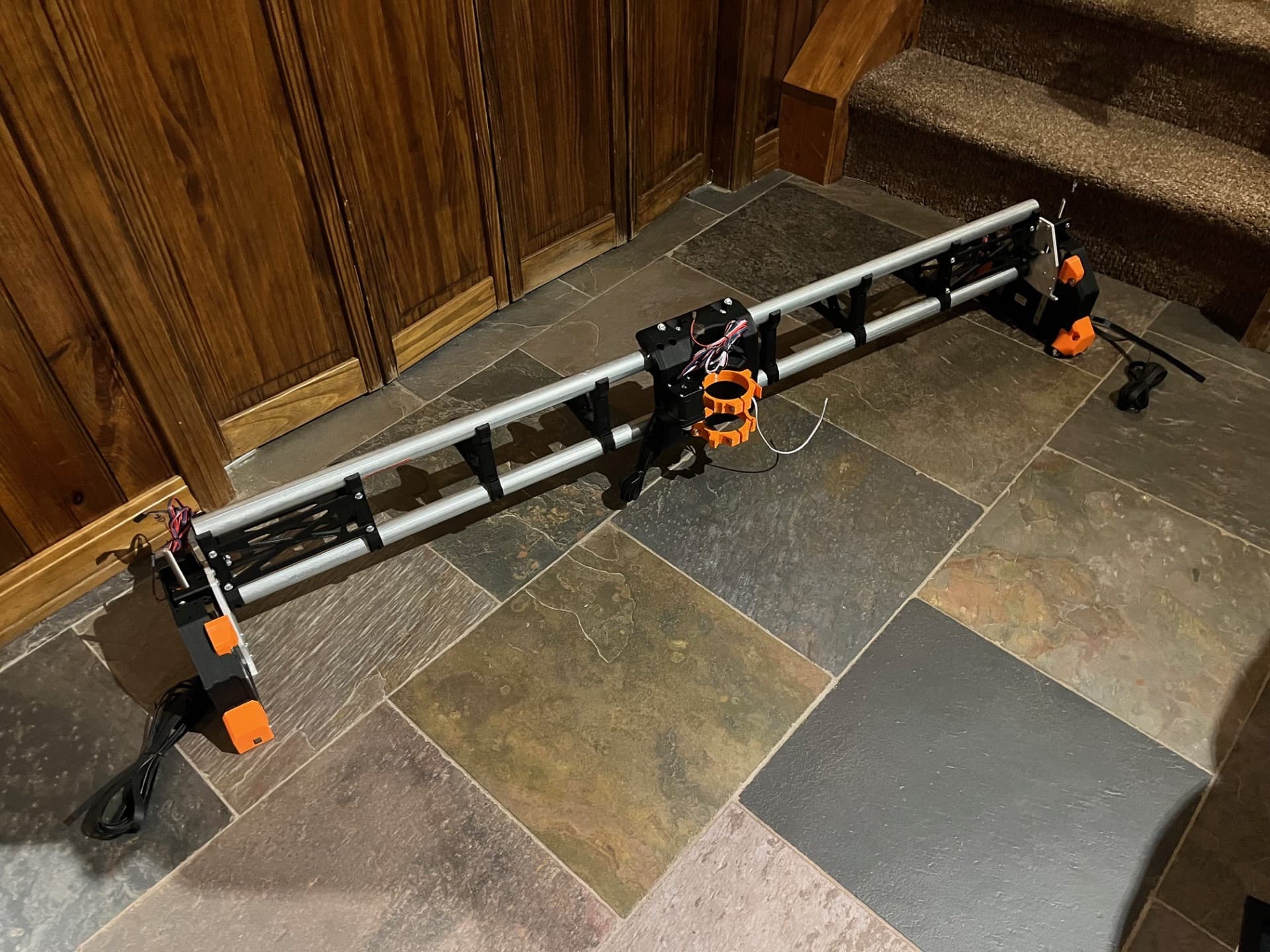
I got a bootstrapped table laid out a week or so later. I knew it’d be on the ground for a few weeks so I laid some plastic down as a vapor barrier and lifted the spoilboard up of the ground on slats. All to prevent it from picking up too much moisture. I did a rough wiring job down on the floor and got it moving. Next I squared things up before cutting my strut plates.

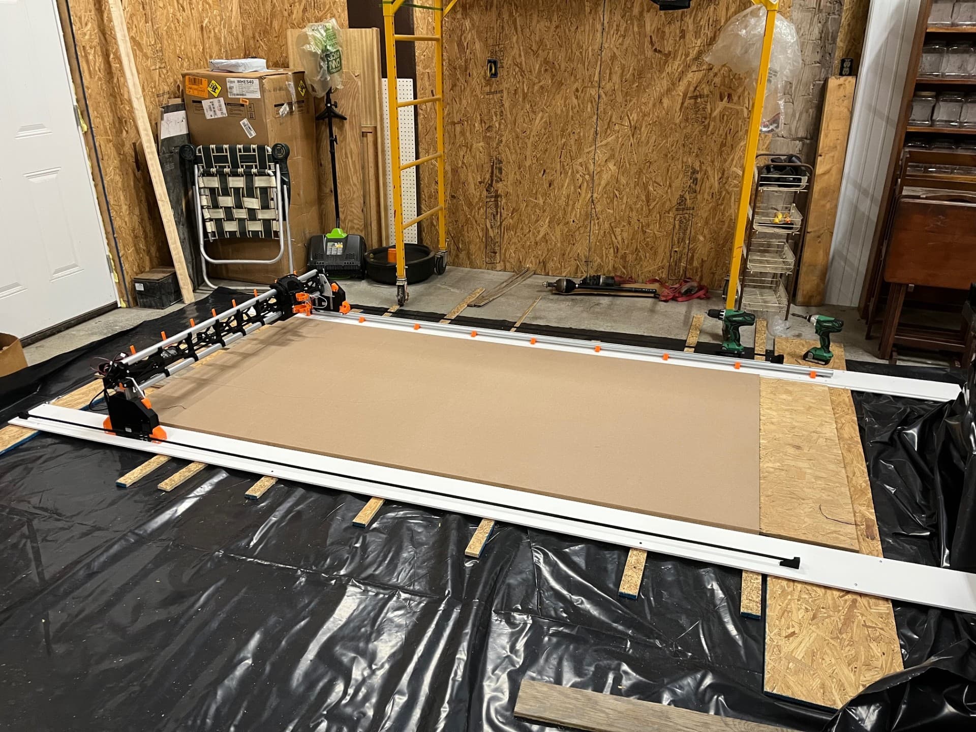
My strut plates cut fine but the next test I ran, the Z height dropped on me. Z dropped to the point where the collet nut was rubbing on the workpiece. Following this failure I increased the Z axis run amps from .8 to .9 and I increased the Z-axis hold amps from .7 to .8. I have not had any issues with the Z plunging since making this change.

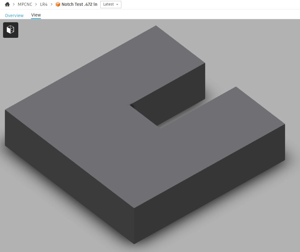
Before cutting my table I made a notch test to make sure that a .472” wide cut will indeed slot into another piece of plywood. This may be haunting me now. The samples did indeed slot together but were quite tight, needing a mallet. Slots measured about .455” which I attributed to some fuzz. Outside dims of the piece were about .011” oversized.

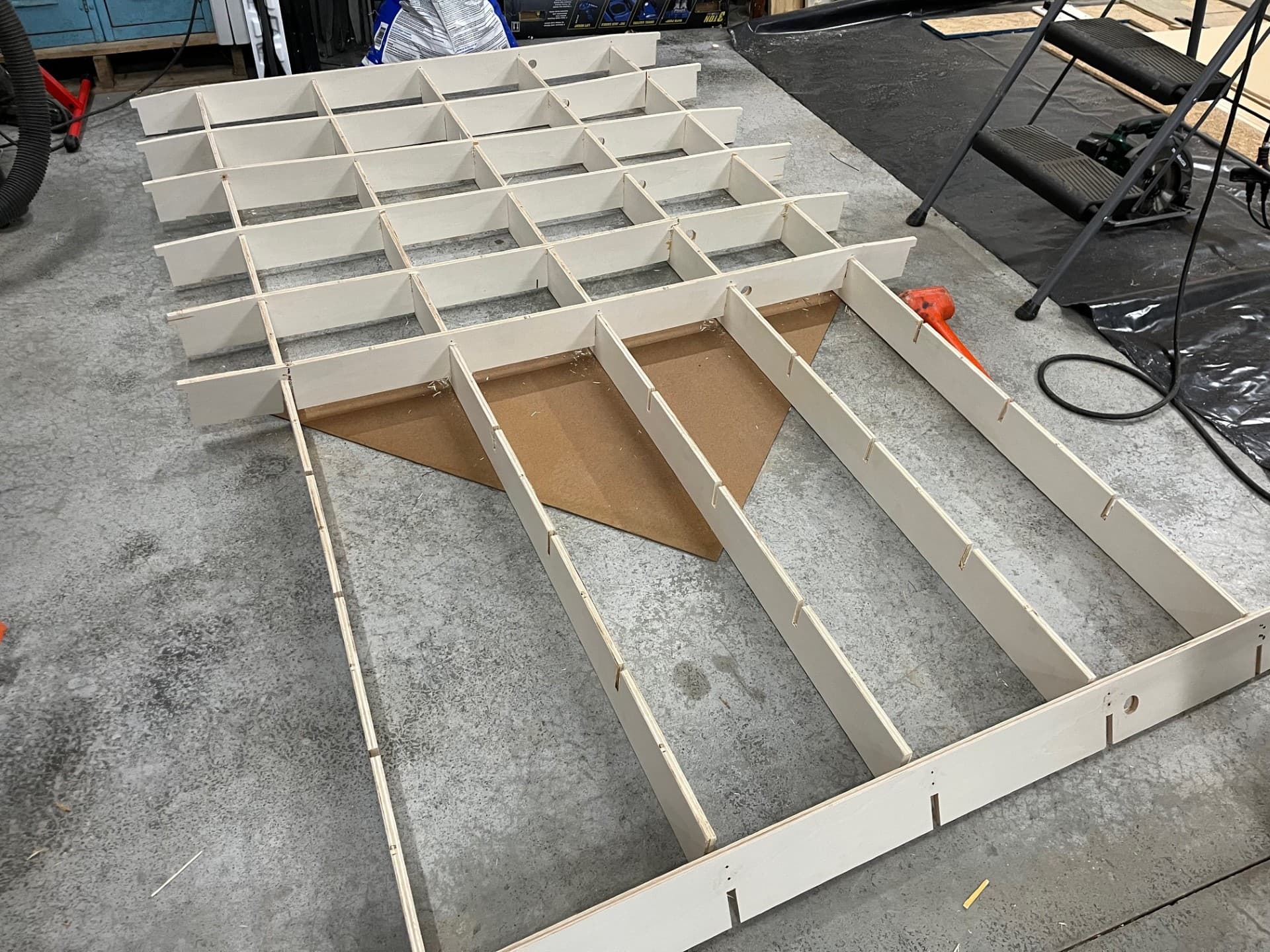
Now I’m in the process of cutting and assembling my torsen table. I took Doug’s file and modified it to closely match the official table. I changed Doug’s to 1/2 in ply, made it 4 in tall, I increased the number of X and Y members to 10 and 5 respectively. I also adjusted some internal table dimensions.

I added a hole in the X-rib for a pivot. I plan on building a cart that the table can pivot onto. Then it can be moved out of the way if I have other large projects in the shop. Inspired by “SATXDIY Sean White” on YouTube.

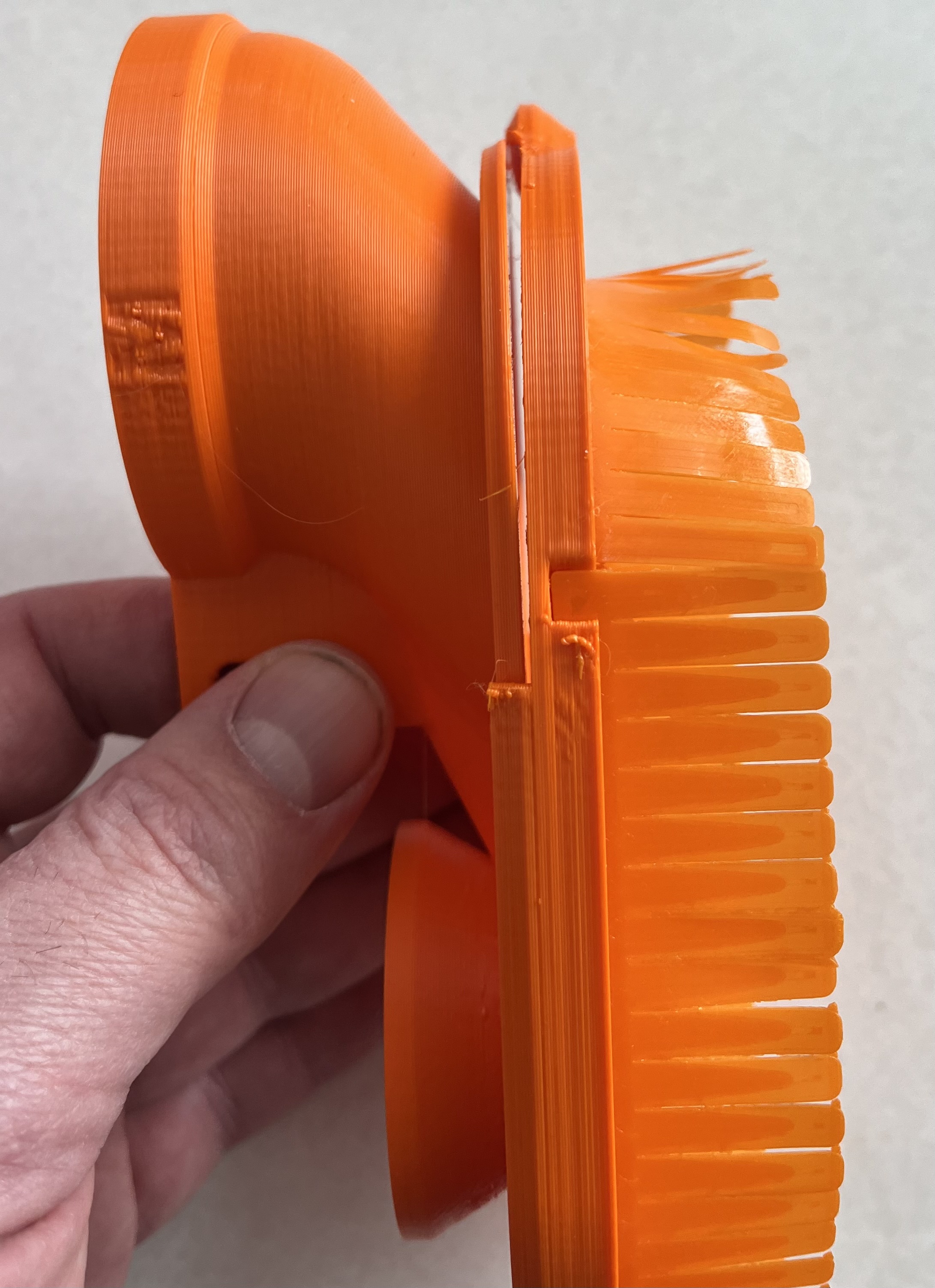
I am looking forward to getting the table built. I need to get this thing and up off the floor and get some dust collection on it. In a hurry, last night I had some time while the LR4 was cutting out the final X-ribs and I tried to start the table assembly. Well, my notches were pretty tight and now I need to cut 3 more X-ribs. I will take my time, chisel out some more clearance, and use a board over top of the rib to do my mallet beating on…

My plan for electrical is to mount a 6 gang box with,

  • e-stop
  • 1 main power switch
  • 1 manual router switch in series with the SSR
  • 2 SSR switched 120v outlets for router and shop vac
  • 2 120v outlets that are switched by the main power switch for the 24V power supply, etc
  • 2 120V constant outlets for computer/tablet

Depending on the room in the box I may add buttons for feed hold, start, and probe. I’ll probably run a length of CAT-5 from the box to the jackpot regardless. From what I read the physical buttons and the FluidNC Jog dial pendant are mutually exclusive. At this point I’m giving the pendant more time to solidify their implementation. (which is code for “I’ll probably start on it next week”)

With any luck I’ll have the table built and have the thing running again this weekend.

Bill

8 Likes

Table looks great! And now that I have built one I would have much rather had the notches like yours. It took forever to put together a table for a 3 x 5 LR4

1 Like

Congrats on the progress and thanks for the updates and info! Look forward to seeing more!

1 Like

Your build is looking awesome so far!

I’ll be very interested to see how your pivot table works out.

Pendant and remote IO continues to evolve in the FluidNC ecosystem.
You’ll have options.

Great progress!

1 Like

Thank you all!

I figured it would take forever to assemble a 4x8 table with individual pieces. Plus I didn’t figure I’d get the boards perfectly on plane making the spoilboard surface undulate like a links course.
I just need to get my slot width corrected, then I’ll be happy.

The plans are churning in my head, this will probably be a ways out though. Sawhorses for now…

Pendant looks great so far, looking to see how things progress!

1 Like

StdTable

SwappedTable

Is swapping X and Y and moving the 0,0 point as simple as what it seems in my head?

  • Move (or add a second set of) limit switches on opposite side of gantry
  • Swap servo wires & endstop wires in jackpot terminals
  • Update config.yaml for max_travel_mm:

Is there a “Gotcha” that I have not taken into account?


Also, what are people doing for a dust shoe that is fairly loose?

Binder clip? Build things up a bit with a 3D printer pen?

The “gotcha” comes in if you need any support. Its a REAL pain to support ones that aren’t set up like a standard CNC. It becomes extremely confusing. The endstop locations are there to use if you just have to have it that way. But I highly suggest you build it stock first and try it. There are a lot of things that once you see how it is youll find they work well the way they are meant to.

2 Likes

For tighter fit, vaguely recall someone scaling down X and Y dimensions to 99.5% for the Dust Skirt part within the Slicer when printing.

1 Like

Well, personally I find it just as easy to arrange my CAM to the reality of the table, but the LR4 has the provision for limit switches the other way around, so there is hardware support for doing it that way.

Some of us can help, sure, but it’s not the easy way. The machine itself is easy, the controller firmware is where all of the gotchas are.

In the standard, X has one endstop and motor. Y has two endstops and two motors (and two motor drivers). To swap them, you have to swap quite a few x and ys in the config. But it can be done. Test every endstop and jog motion before you home and you can make it work. I would suggest making it the default way first and then only change it once you know what to expect.

3 Likes

Thank you. I knew there had to be something else I was missing. Otherwise I just don’t see the conplexity of the config change.

The way my shop is configured my machine will be up against walls in the +Y and +X directions (Standard config). I’ll be free to load 4x8 sheets from the -Y but slipping things under the gantry seems somewhat cumbersome. As does running the gantry all the way +Y to load and then all the way back again to home.

If the axis were swapped it’d seemingly solve all of those issues.

I’d also plan my spoilboard workholding pegs diferently based on the orientation so that’s why I was looking to make the change sooner rather than later. I can run with it and see how it goes…

2 Likes

I made mine from 1/2" ply, broke many joints because of the mallet beating… it wasn’t until near the end I realized that the joints were tight but correct size and I only needed to use a cheap clamp to push them together flush… was so smooth I kick myself for ever picking up the mallet. I may even build another one just to press them all together without a single crack. :slight_smile:

2 Likes

Thank you! Running to get clamps from the garage now…
Edit: Oh that works Sooooo much better!

2 Likes

As mentioned above, the single X and dual Y has to become dual X.and single Y.

In Marlin there’s a few changes required in the configuration.h file, which are documented in a couple of forum posts.

I’m not sure if anyone has done this in FluidNC (Jackpot) yet.

@DougJoseph , have you gone Landscape mode on your LR4 yet?

1 Like

I used these, worked perfectly

2 Likes

Yes, I just tried the clamp method and that is definitely the way to go. Thanks for that recommendation.

Need to try and be smart and not revert to my Neanderthal roots!

1 Like

Yes, my Jackpot was already running swapped X and Y before the update to LowRider v4, and I still maintain that with the LR4. There’s more than one way to skin that cat. You can either swap the X wire and Y wires, or edit the config.yaml file. Either way is easy, and I think I have done it both ways (my first swap of X and Y was back when I was using Marlin on an SKR Pro board).

This is how my table is set up. My long axis is X and the short axis is Y. Personally, I like it. It helps me make this work in the tight quarters of my space.

In earlier versions of LowRider, I had to modify to get the short axis to home to the side opposite of normal (ie. non stock), but the new LowRider v4 offers that functionality as an option in the design. The core has two spots for a limit switch, one on either side. Just mount the limit switch on the other side.

For the long axis (normally Y, now to be X) the physical setup does not require any changes to limit switches unless you want your machine “facing backwards” when it homes, or, you want it facing forwards but also want your Y belt tensioner screws to be on the front (minimum side, near 0) which I do… There again, the new LowRider v4 allows mounting limit switches on either end of a side assembly, and has some end stop “real estate” on the belt mounts on either end.

In my case, my table has metal struts (aka superstrut) that my machine rides on, and so I did some custom designed printed “table extender” inserts and did a remix of the belt tensioner parts. My screws for adjusting tension on long axis are at the front of my table.

On mine, I got there by swapping axes: the long axis is X and the short axis is Y. That is still standard as far as CNC world is concerned. No weirdness at all in CAD or CAM or gcode.

1 Like