Bartman's LR3 build thread - A New(bie) Adventure!

I’m super stoked to start my LR3 build. My Ender 3 Neo is mostly set up and working, and my first roll of filament (Hatchbox PLA black) just arrived, with a second roll (same brand in red) scheduled to arrive tomorrow. I’ll spend a bit of time making some test prints with the new filament, ensuring for dimensional accuracy and squareness before starting to print the parts.

I’m going to build the LR3 in small scale first using printed parts for the XZ and YZ plates. I’ll start by using one 10’ piece of EMT cut into smaller pieces to give me an approximate usable area of 36"x36" (1m x 1m). I’ll use that to dial everything in correctly, and to cut the final XZ plates out of 6mm (1/4") aluminum, and the YZ plates out of either aluminum (2 x 6mm aluminum plates epoxied together?), 12mm MDF, 12mm acrylic, or possibly 5/8" plywood (depends on what material presents itself). I may use Ryan’s steel XZ plates instead of cutting aluminum ones, but the idea of using the LR3 to build it’s own parts is intriguing.

Once the flat parts are milled using the temporary setup, I’m going to replace the X EMT pieces with longer 1" 304 Stainless Steel (0.120 wall thickness) that I just picked up today. I’ll have to print new braces and discard the smaller ones, but with the size of the final build, I think that the stronger tubing will make a difference to overall strength and rigidity. Y rail will be 3/4" x 10’ EMT

That brings me to the table, which is going to be 72" x 120" (6’ x 10’). with a usable cutting size of 59.5" x 105". I’ll be building a torsion box (approximately 5" deep), with lapped X and Y supports every 12", a full skin of 1/2" plywood on top, and a 4’x8’ sheet of 1/2" plywood centered on the bottom. There will be a 49" x 97" sheet of 1/2" MDF as a spoil board. Legs will be pocket jointed pieces of plywood in each corner, with adjustable insets to allow for different working heights (28" - 36"). I’ll set up the LR3 on a temporary surface to cut all of the table pieces.

I’ll be posting pictures and CAD drawings in this thread as things progress, so stay tuned.

5 Likes

Post pics!!!

1 Like

:open_mouth: Huge build! For me the table would be trickier than the LR3 build. Look forward to build progress pics. Nice sturdy pipe for that long gantry makes sense. Good luck!

2 Likes

A couple of questions for @vicious1 about ordering the pieces that I won’t be making myself:

I’m getting ready to buy the Hardware Kit ($306) and the SKR Pro1.2, 5x 2209 drivers, TFT35 E3 V3 -flashed- ($139.99).

I wanted to buy the Tiny Touch Plate Kit ($8.49) , but it shows that it may be out of stock. Can I pay for it as part of the initial order and have it shipped for free when it arrives, or would I have to buy it later and pay for shipping?

I want to buy the Wire Sleeve ($0.38/ft). How much would I need for a 6’x10’ (approximate) build?

Do you have 1/4" steel XZ plates available, or only aluminum (the shop page only mentions the latter). If so, are they the same price, and how do I specify that in the shopping cart? Is there any benefit or drawback between the two?

What end-mill(s) do you suggest? I will be primarily cutting full sheets of 3/4" plywood, with some 1/4" aluminum, 1/2" acrylic, and eventually some carving of wood and plywood.

Are there any parts that I am missing on my list? (As mentioned above, I will be printing and/or milling anything that can be made on a printer or on the LR3, with the possible exception of the XZ plates)

I’m using the table size to determine the usable area, rather than the other way around. With a 49" x 97" MDF spoil board, the table size is already 62" x 112", and I wanted to build the table with 12" centers for the lapped supports, so it made sense (to me at least) to build it out to the next multiple of 12" in each direction.

I’ll be side-mounting the near side belt so that I can park the LR3 at one end and use the table surface for laying out and assembling the cut pieces. The extra room will make it easier to move things around without hitting the LR3.

3 Likes

Sounds awesome make sure to share some pics.

There are plenty, just the extra refill plates are out.

6’

Only AL now.

The smaller the better. It can nest in a table no problem. If you can’t get material that big you should not build it that big. Most importantly, the X axis(beam length). The shorter the better. The smaller it is the easier and faster and more accurate every single cut will be.

2 Likes

Pictures you say…?

Well, it’s pretty early in the game, and I’m just at the point where I can calibrate the printer with the filament that will be used, but I’ll post pics of the progress so far.

To quote Julie Andrews, “Let’s start at the very beginning. A very good place to start…”

This is the printer I will be using for the build. It’s a Creality Ender 3 Neo. Similar to the original Ender 3, but with a metal nozzle, glass bed, and built in CR Touch probe. I bought it pretty much to build the LR3, but my wife has some other ideas.

I had a bit of a learning curve to get going. Putting it together was pretty straight forward, but the instructions for bed leveling and setting the Z-Offset were pretty vague. I toasted the glass bed on my first attempt to print a Benchy…

:frowning_face:

So off to Amazon we go to purchase a new glass bed, and then to Youtube to learn how to properly level the bed and set the offset. Several days later, the second attempt at printing a Benchy looked much closer to what it is supposed to:

So now that I have a better handle on setting up the printer, it’s time to start gathering up the materials needed to start the build. After asking around the forum and reading different threads and reviews, I settled on Hatchbox PLA. I’m going to print a mix of red and black parts, and I haven’t quite finalized which parts will be which colors yet, so I bought a spool of each, and will get another spool or two as the build progresses (next day delivery from Amazon Canada, so easy to restock as necessary).

I also bought a dial gauge to help tune the printer bed level. I had borrowed one from a friend and it worked like a charm!

Christmas in July!!!

Not shown yet are the 1" 304 Stainless Steel tubes (0.120" wall thickness) that I purchased for the gantry, and the several pieces of 6" wide 1/4" aluminum flat bar that I recovered from a scrap bin, and that I am hoping I can use to mill the XZ plates from (need to check the drawings to find the dimensions).

Next up on the list is to place the order with Ryan for the Hardware Kit, Controller/Driver/Screen kit, Touch Plate, Cable Tube, etc. I’m just holding off until I research which endmills I want to include in the order, but I’m hoping to put the order in this weekend at the latest.

Then it is several days (probably weeks) of printing parts. I’m working full time at the moment, so I only have a couple of hours in the evening to spend on this, so it may take some time to get to the stage where I can assemble all of the pieces into a working unit. I’ll post some more pictures as I muddle my way through the process.

Cheers for now!

6 Likes

Well looks like your well on your way !!
Also a fellow Canuck too
Good luck

1 Like

So I have almost all of the non-printed parts here. Shipment arrived from Ryan (haven’t opened it yet, so no pics).

I purchased a knockoff Makita router - Vevor 1.25HP. VEVOR 6.5Amp 1-1/4 HP Wood Router Tool Kit Max Torque 30,000RPM Variable Speed Compact Router Kit With Fixed Base, Plunge Base, Tilt Base and Offset Base (kit w/4 bases) | VEVOR CA It came with 4 bases (tilt, plunge, offset, standard) for an extra $14 CDN (about $10 in real money), plus vacuum port and a bunch of spare bits and bobs. I won’t need them for the LR3, but I will probably use the router for hand-finishing a few projects, so for the extra few bucks, it seemed like a reasonable idea.

I found a few additional pieces of 1" x 0.120 Stainless Steel tubing (37" long), which I can use to build the smaller version to cut parts as I’m building the full size version, so I won’t have to print and discard the smaller diameter braces as originally planned…

I also found several pieces of 1/4" aluminum plate, so I think that I have most everything I need to start putting it together once I print all of the plastic parts.

On the printing front, I’m making progress dialing in the new Ender 3. I checked the e-steps for the extruder, X, Y & Z axis. The three axis were all within 0.08 mm over 100 mm of travel, so no adjustments necessary. The extruder only pushed 94mm of filament on a 100mm command, so I adjusted the settings and now it pushes 100.07mm (pretty darn close).

I had already leveled the bed, set the Z Offset, created a bed mesh, and tuned the PID for the nozzle and bed. I then printed a single layer bed adhesion test file, and it came out pretty good, as far as I can tell:


Sorry for the crappy pics - photography is not my strong suit.

The rectangles look like there are no voids or gaps, and they were sticking really well to the bed in each location.

Next was a skew test.


The adhesion of these to the bed was through the roof! I literally had to remove the glass plate and use a scraper as a chisel to remove them.

The XY test was within 0.05 mm (100mm rectangle, 140mm diagonal), so that was pretty good.

The XZ test was also pretty close (0.02mm difference), but there is a lot of stringing, along with a bit of elephant foot. Not sure if that is because of the filament (the white stuff came with the printer, and has been exposed to the air for several weeks), or because I still need to dial in the temperature and retraction settings. Now that I have used up the old filament, I’m going to load up the shiny new red Hatchbox PLA and do those tests next.

The YZ test was a little bit less where I was hoping, with about 0.70mm difference, and again lots of stringing and elephant foot issues. Not sure if this is a reasonable amount, or if I need to compensate in Cura or in Marlin. Once I dial in the temperature and retraction settings a bit better, I plan to re-print that test and see how it looks. I should hopefully also be able to do some of the shorter pieces (pretty much everything but the core, I’m thinking) as is, and maybe try to fine tune it a bit more before tackling that one.

I’m getting a bit more knowledgeable about the 3D printing process, so once I get rid of the stringing and pachyderm appendages, I can hopefully start printing my first parts for the LR3 by early next week!

.Comments and suggestions welcome!!!

2 Likes

Oh yeah, also bought several heavy duty vacuum bags and a 50 count bag of 5g desiccant packets to keep my filament dry when not in use. I saw someone online using the heated bed and a cardboard box as a dryer, so maybe I’ll give that a try as well.

3 Likes

I’m a strong advocate for the Teaching Tech 3D Printer calibration guide here: https://teachingtechyt.github.io/index.html. I followed that to really dial in my printer after I made a lot of modifications to it (it’s basically not at all stock except for the frame and wiring, I’ll show it in my thread tomorrow). Lots of good tips on that site, and he walks you through things like step adjustments and such using both videos and text. Really well done.

Re: bed adhesion, Elmer’s glue sticks are my go-to. Enough adhesion that filament doesn’t try to escape the bed, but not so much that it’s impossible to remove parts. I do keep a very sharp chisel by the printer to carefully aid in part removal, but I don’t always need it. Kind of depends on how much glue I laid down. :melting_face:

Re: elephant’s foot, there’s a setting in Cura - Initial Layer Horizontal Expansion - to reduce the first layer outer width by some small fraction to help keep the plastic from squishing out as much. I set mine to -0.1. Also, getting the bed temp and fan settings right will help.

Re: stringing, you’ll get that sorted via the calibration website. You will do a temp test to find the best temp for your filament (it can vary from brand to brand), and then a retraction test which is likely a factor in the stringing.

The process is fairly involved, but worth the time to nail your settings. I’m going to be upgrading my machine with linear rails soon (the wheels on the X and Y axes are wearing out and linear rails are overkill but awesome), so I’ll be going through the whole process again to get my rig tuned back up.

2 Likes

I had that too on my Ender 3 V2. In the end I swapped the glass plate for a pie plate as I was unable to remove some printed parts without nearly damaging the glass one :melting_face:
Had a small learning curve on the Pei one though, as I had 0 adhesion after installing. Since I cleaned it before each print with 100% IPA that was solved (except for prints with very small footprint, there I need some additional support).

Regarding the stringing, I would suggest to print a temperature tower with your PLA you will use most of the times. Nearly all guide I’ve read mention around 200 degrees for PLA but found out that my setup works better with 190 degrees. So use guides loosely

1 Like

All right, I’m happy to report progress! After dialing in the Ender 3 (New to 3D Printing - Advice for LR3 Print Settings), I just printed my first LR3 part!


More pics soon.

4 Likes

Thanks for that. I’ll give it a try on my next print!

1 Like

Well, those last 18 days have flown by!!!

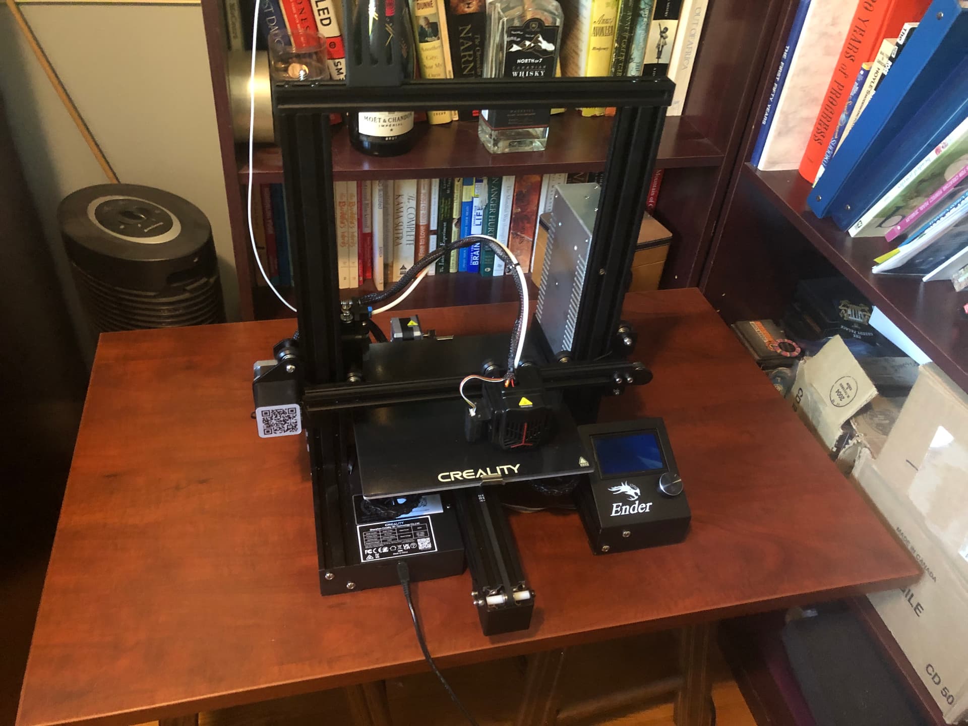
So I’ve made some progress with printing (some of) the parts, and then ran into a whole bunch of headaches with the printer.

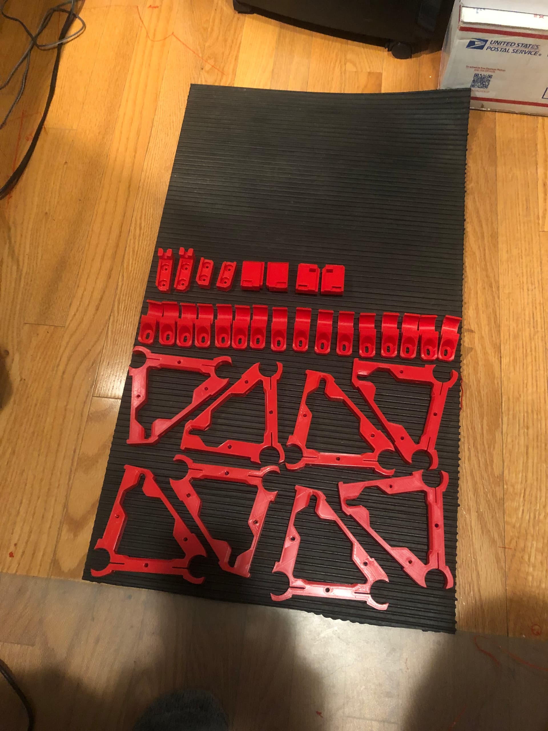
The good news is that I managed to print off all of the Y Rail Brackets, inner X Rail Brackets (50% infill ones not done yet) and the Y Belt Holders/Endstops (not sure if the terminology is 100% correct, but hopefully you can tell from the picture what I mean…)

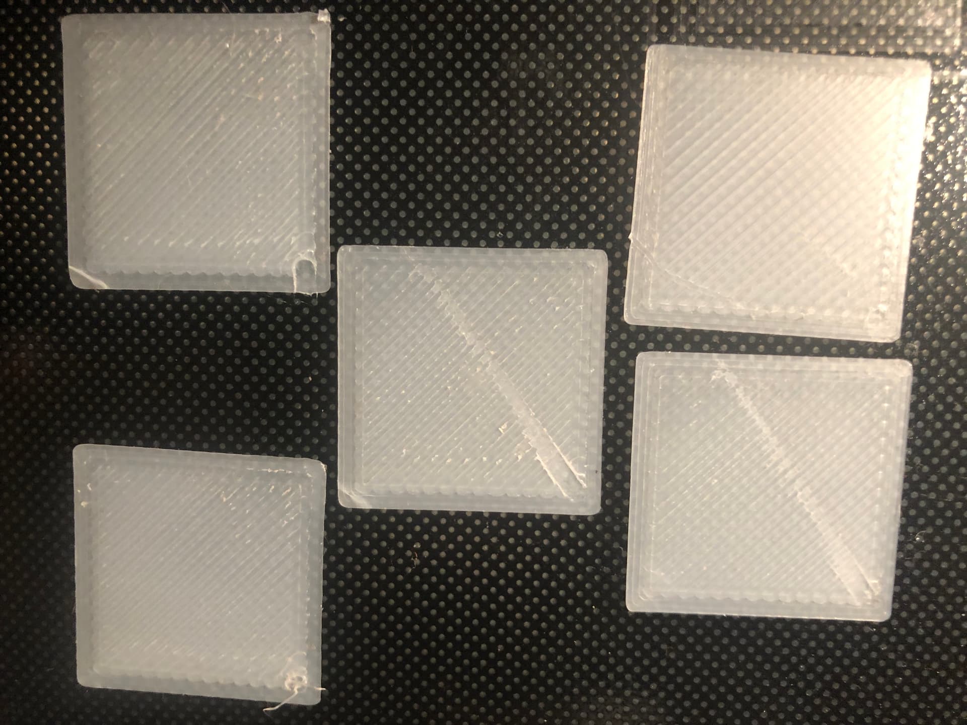
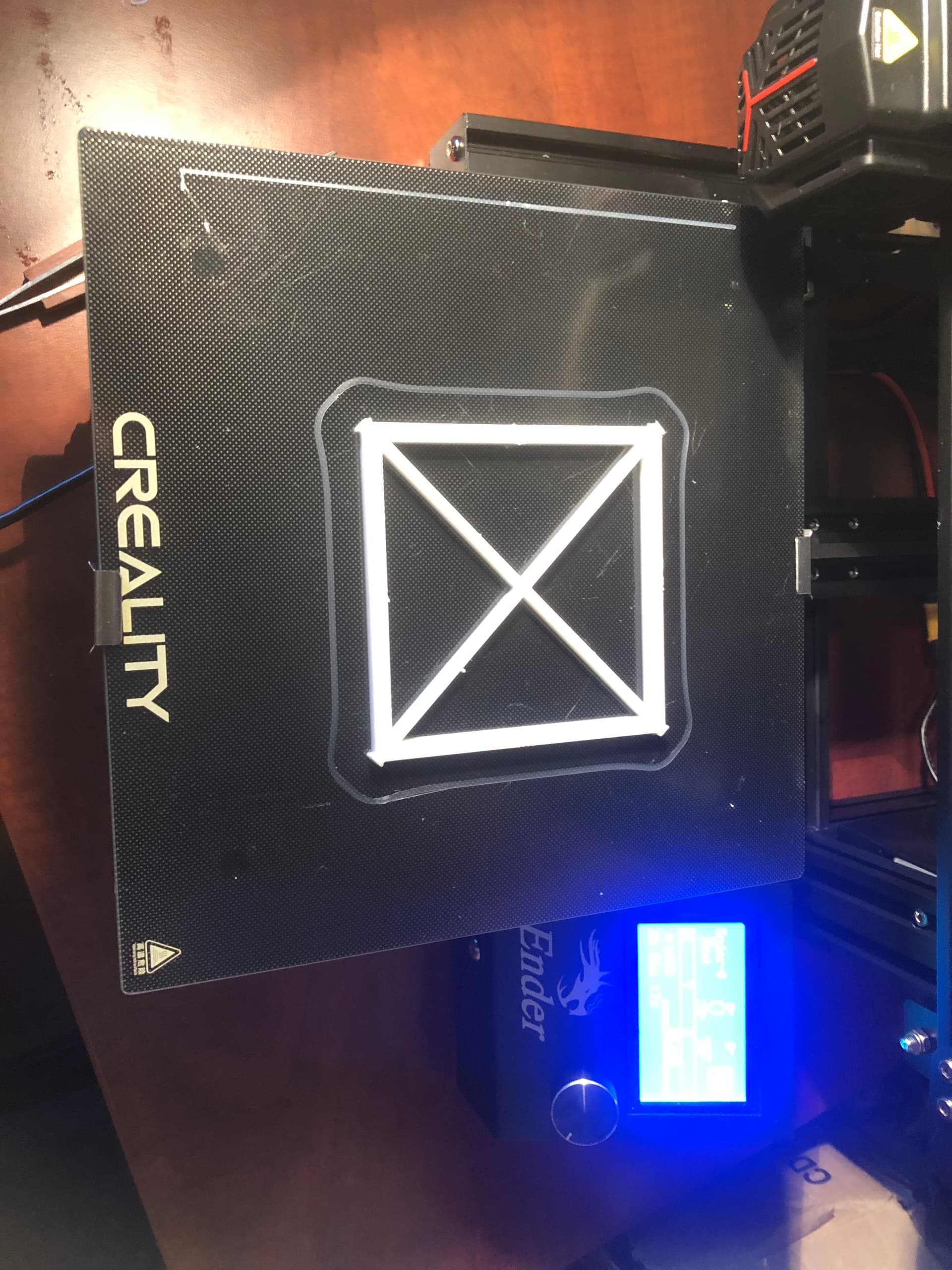
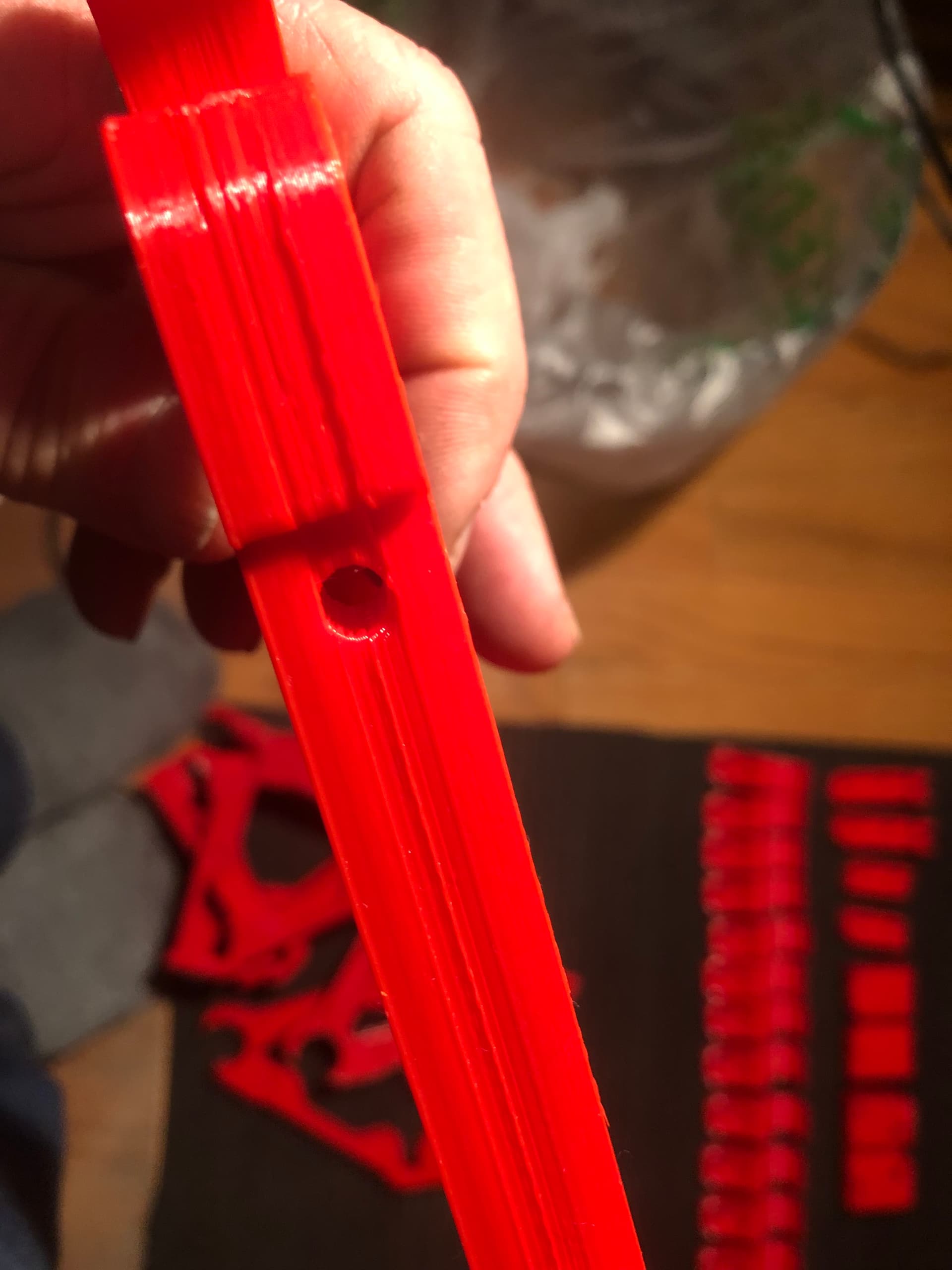
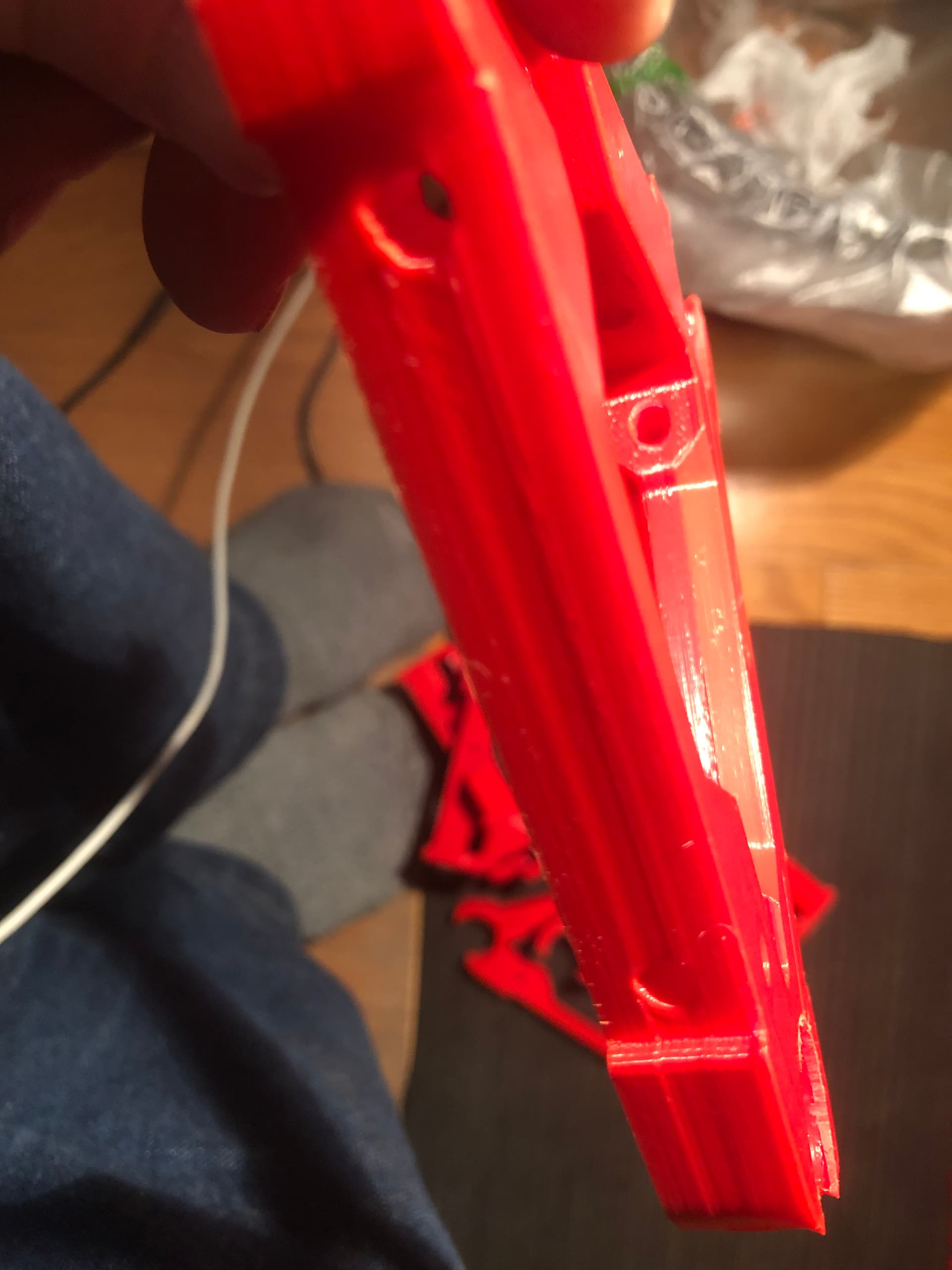
Things were going along pretty well, and I was feeling pretty good about the quality of the prints. Until I noticed that the last few X Rail Brackets were showing some weird lines (layer shifts?) in the middle of the prints

I spent a LOT of time trying to figure out what was happening. I had noticed that the nozzle was contacting the infill during travel moves, so I had made some setting changes in Cura to add Combing and Z Hop, so I wasn’t sure if the lines were a result of the nozzle contact, or from the setting changes.

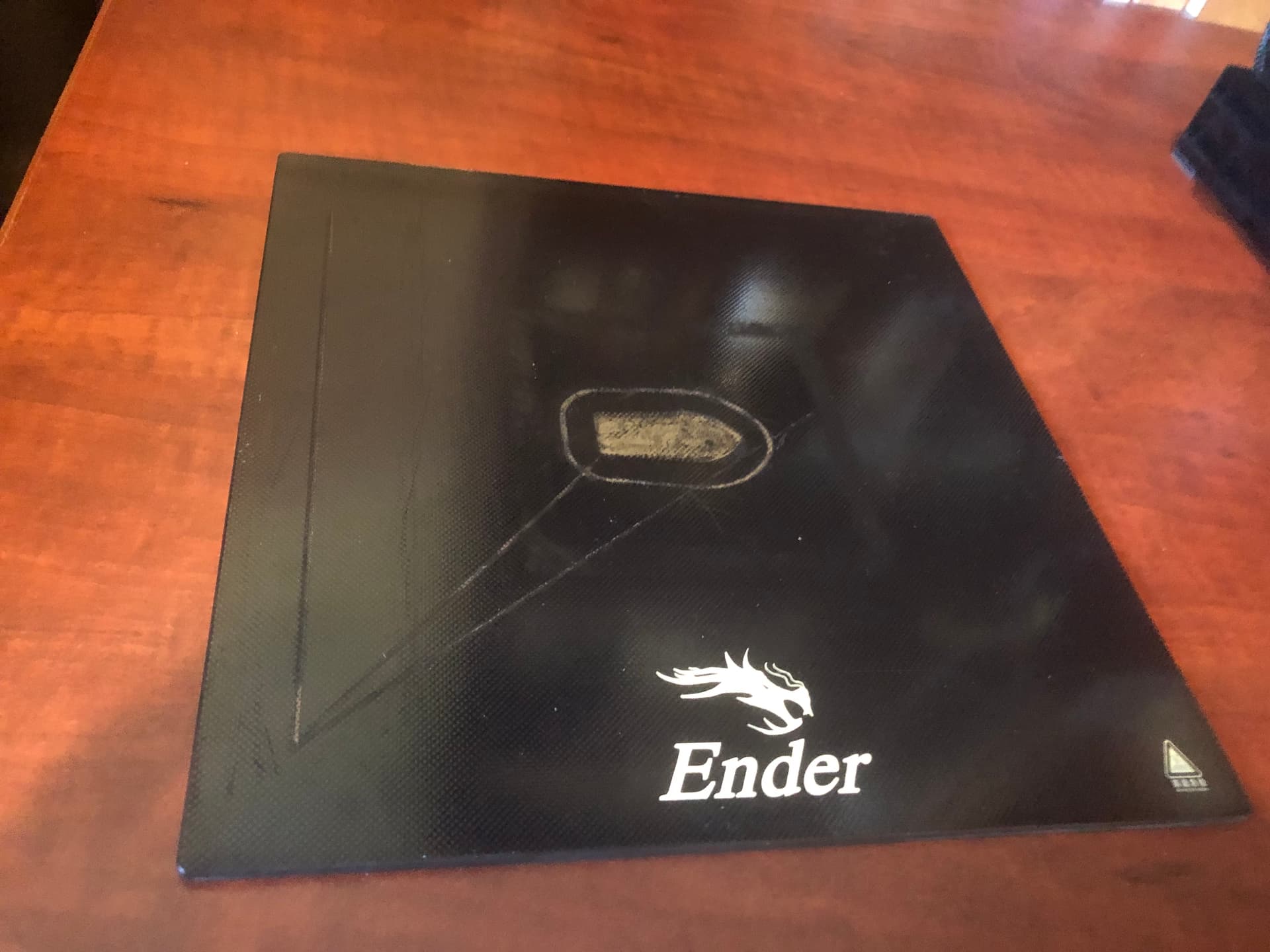
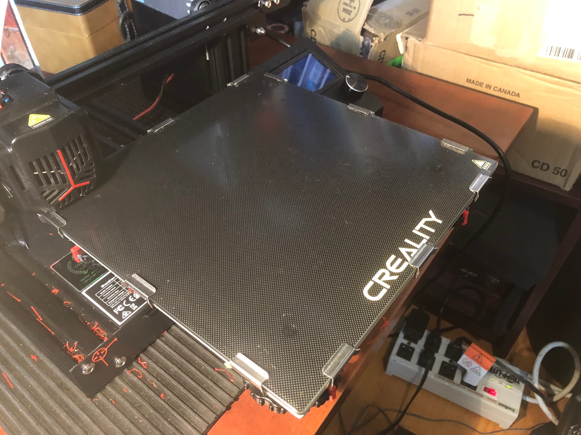
I started to look at the first layer setup, so I re-leveled and trammed the bed (several times), and I noticed that the bed had some fairly serious warping when measuring with a dial indicator. The waviness seemed to be most noticeable near the edges, with the corners raised up and the clip locations (x2) lower than the rest of the bed. The center of the bed also had a noticeable dip.

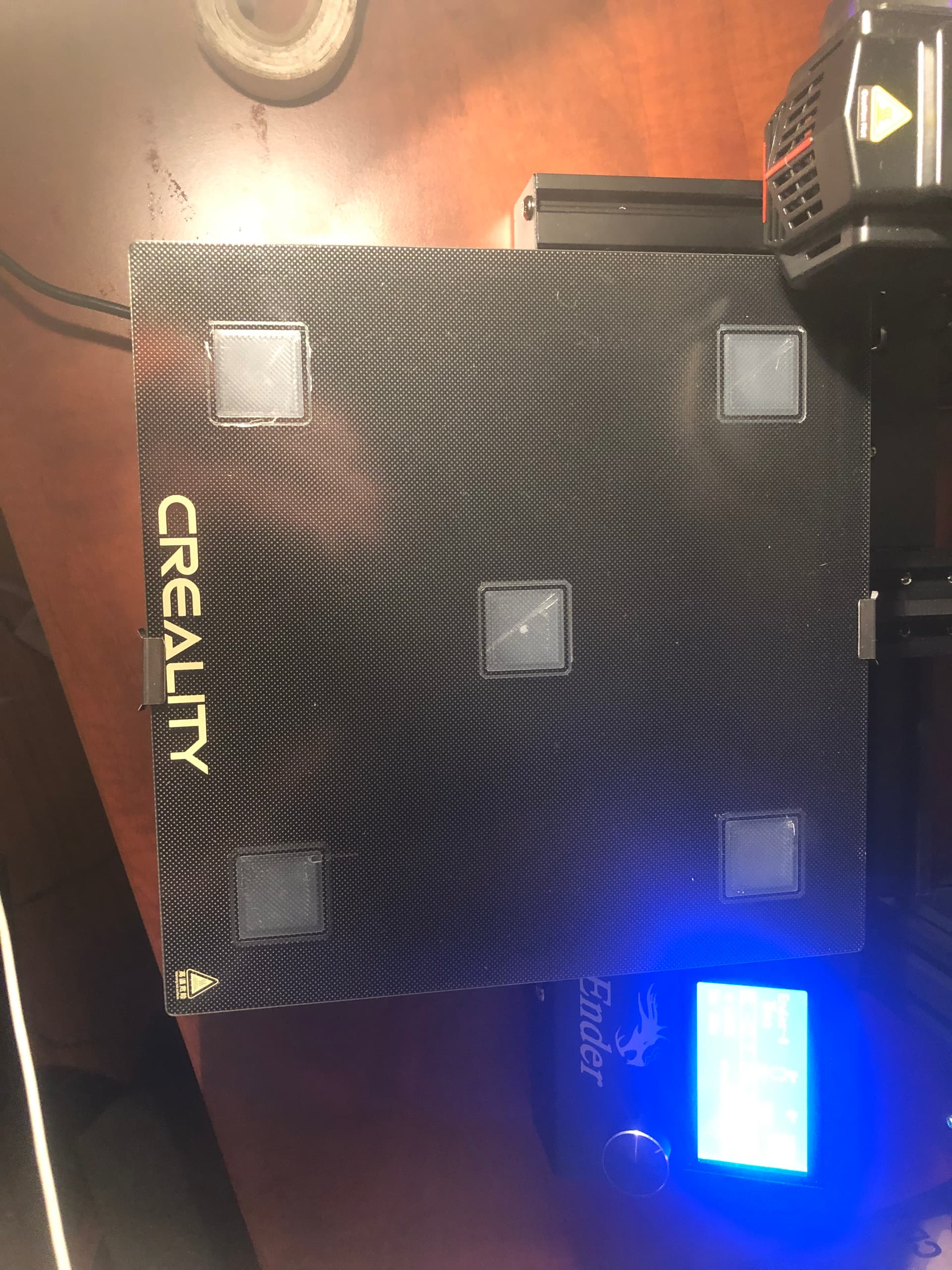
Creality units ship with only two clips, so I bought/installed several more clips (3 on each edge).

The units also use only 16 points (4x4) for the bed leveling mesh (Bi-Linear), so I went down the rabbit hole of configuring Marlin to use UBL bed leveling with 100 points (10x10). That took way longer than it should have, mostly because Creality has not provided the source code for the newer models of the Ender 3, and the only “example” for my model that I found on Github (Marlin Firmware) had a few obvious errors and was not set up at all to use UBL.

I spent MANY hours learning all about G29 codes and how to edit and compile .h files. After repeated mistakes and failures, I finally got the configuration pretty close to how it needed to be.

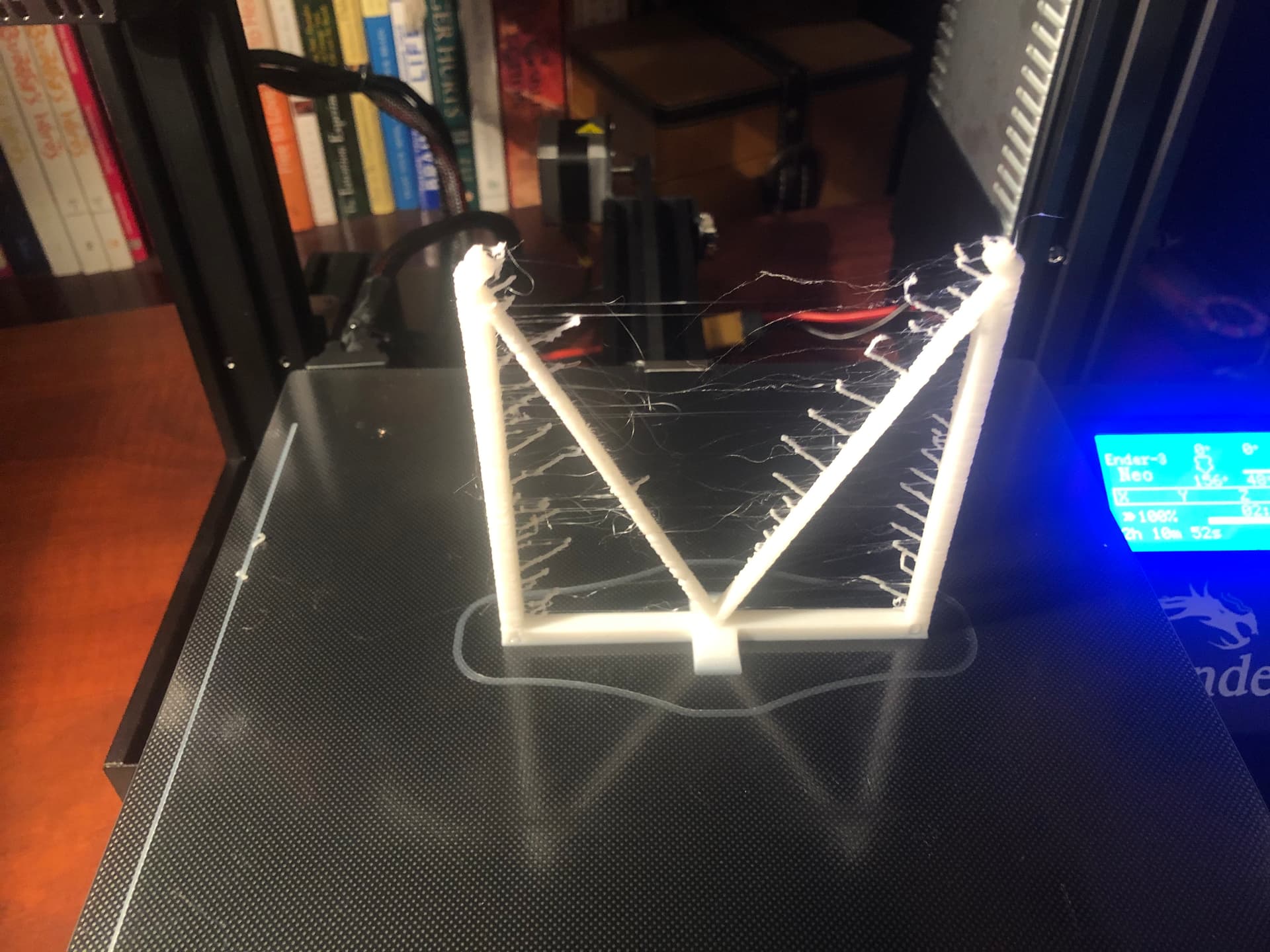
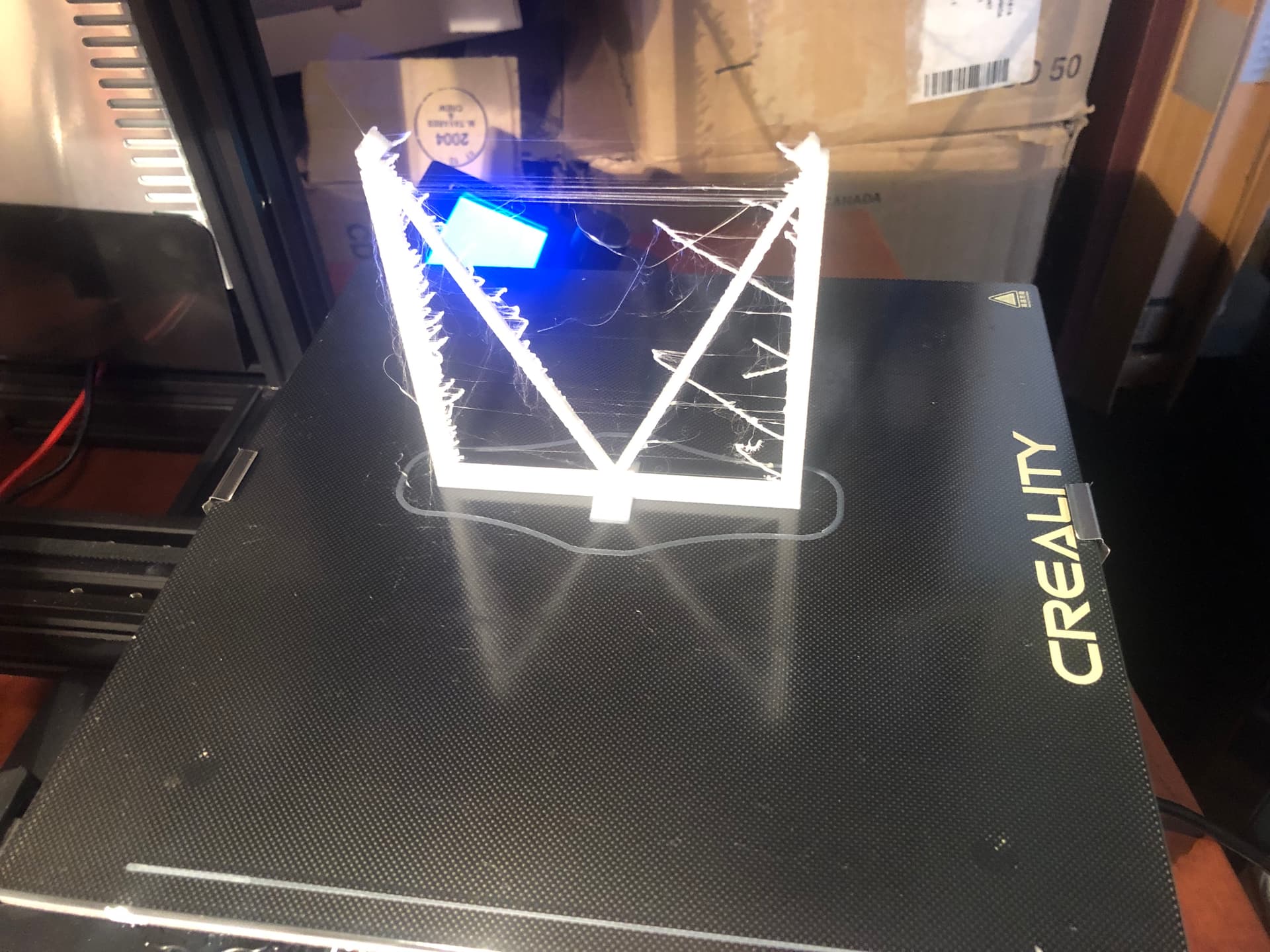
I tried a few test prints, and the results were HORRIBLE! Blobs, stringing, gaps in the first layer, you name it!

I found a bunch of issues:

I found a bunch of scraping marks on the plastic piece at the base of the Power Supply


It seems that the Power Supply doesn’t sit straight on the vertical gantry beam, and was twisting into the path of the bed, where it was getting scraped every time the bed got near the Min Y position. I had to shim the Power Supply on one side with aluminum foil to straighten it out so that it was parallel with the bed.

I also found that the PLA had become moisture soaked from sitting on the printer too long, so I had to set up a makeshift dryer using the heated printer bed and a cardboard box with some vent holes. That and cleaning out the nozzle/extruder seemed to make things a bit better.

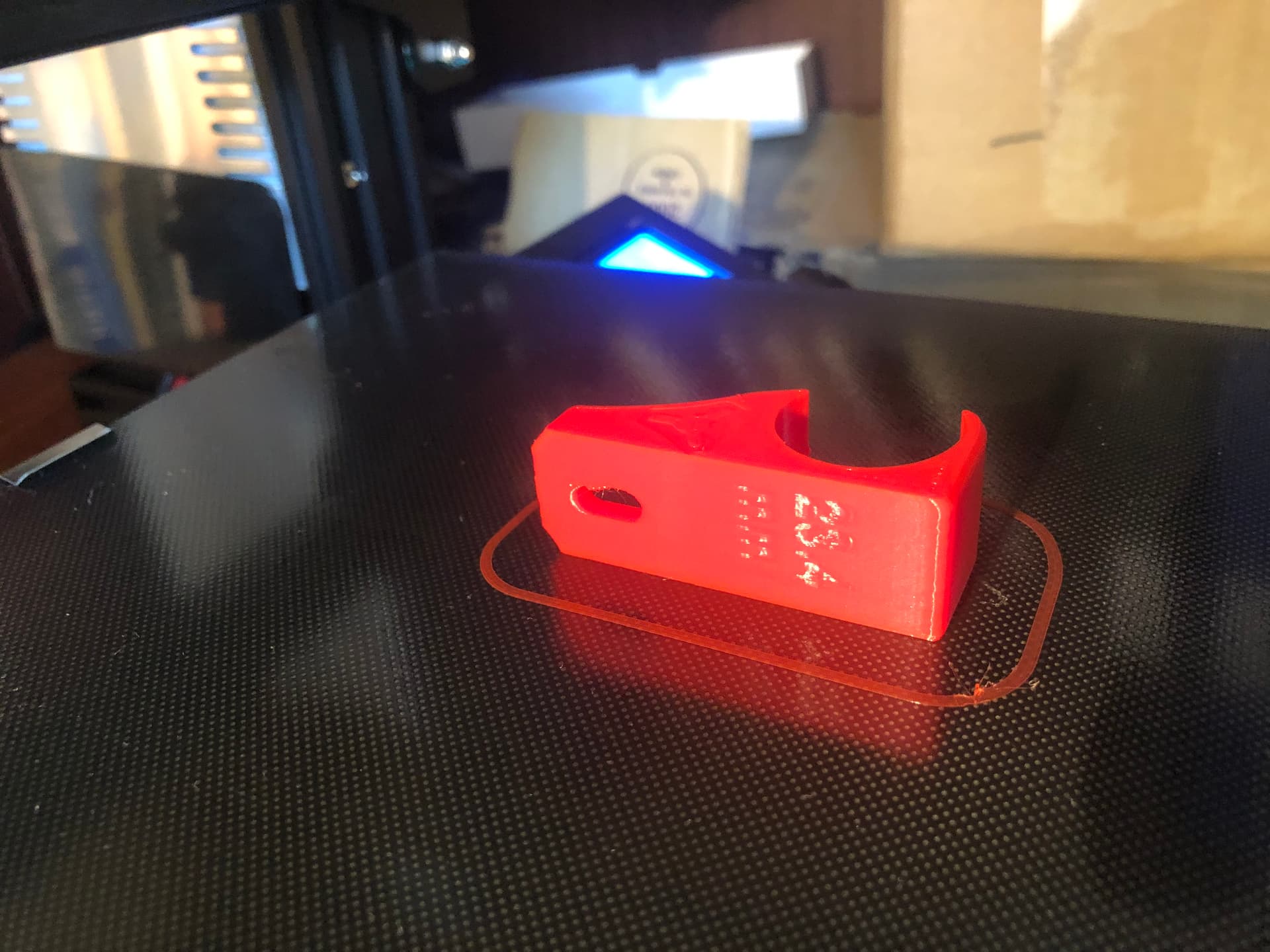
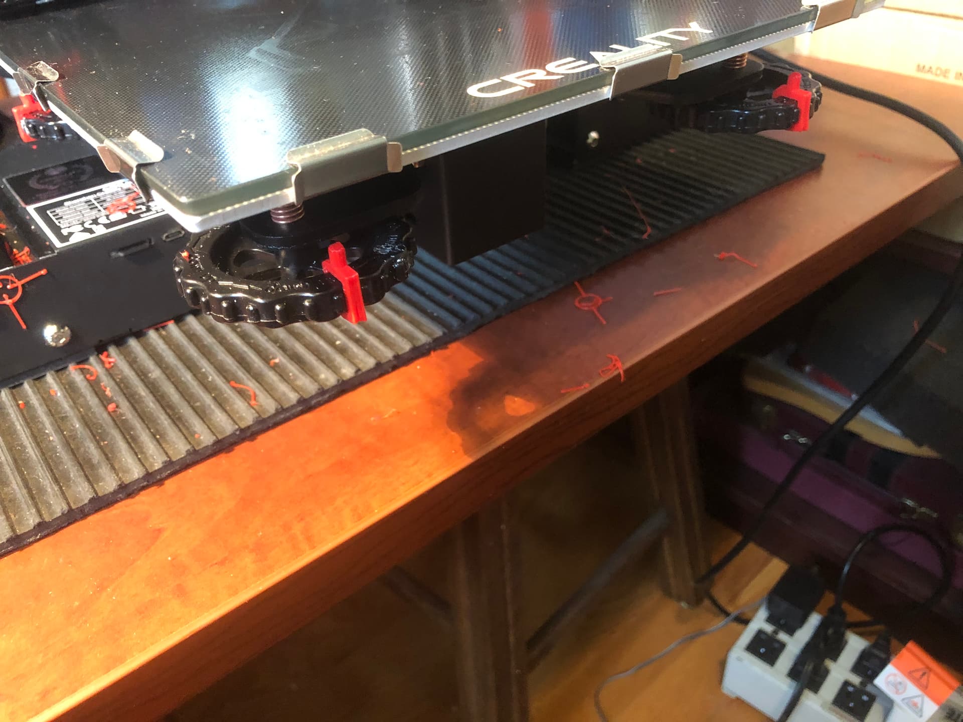
I also found that the bed adjuster springs weren’t tight enough, so they were spinning loose during printing, or whenever my hand brushed against them when changing the SD card. So I tightened them up so that they were about 90% compressed and printed some parts that attach to the adjuster wheels that I can use as a visual reference to see if they moved

(Once I get the printer working correctly again, I’m going to print and install some locks to prevent the adjusters from moving at all).

Lastly I noticed that the nozzle moved around when I touched the Bowden Tube/wires at the top of the nozzle assembly. I took of the fan cover and found that the two screws that hold the nozzle/heat sink to the assembly had come completely loose! I tightened them up, and I’ll check them every couple of weeks going forward (there may be some Loc-tite in their future).

So after all of that, I’m getting closer to having the printer back to working condition. I’m still dialing in the bed mesh using G26 mesh validation test print. Parts of the bed are adhering well, but some other parts aren’t there yet, so I need to manually adjust the mesh points until it is consistent across the entire bed.

Kind of challenging when I only have an hour or so in the evenings to work through all of these issues, but so far the challenge has been fairly rewarding. I’m learning lots about 3D printers, Marlin configuration, g-code, and a bunch of other stuff that will hopefully help me down the raod when I start to build and operate the LR3.

Ciao for now!

That’s really frustrating… but all part of the hobby journey we’re on! I have gone through plenty of 3D printer headaches too, so I feel ya. Glad you’re learning and making progress again.

Yes., if it was easy, everybody would be doing it! LOL. As you say, it’s all part of the hobby journey, and in my case it is really all about the road trip, and not really much about the destination.

1 Like

The appearance of that issue seems to indicate that the Z axis did not advance upward as it should, causing a squishing of layers on top prior layers. Chief suspect would be a loose grub screw on the Z axis coupler (where the lead screw and the stepper motor connect to each other).

If you have not personally insured the grub screw has some thread locker on it, it’s a good thing to make sure. Loctite brand is popular. I use Loctite 243 (blue): Amazon.com

PS: there could be other possible causes, such as friction / lack of lubrication where the lead screw passes through the lead screw nut/block.

Perhaps you could print a small calibration cube? (To see if the problem is there always)