VIDEO: YouTube Playlist just for this!
VIDEO: LowRider v3 DIY CNC - new floating-Z dust shoe - work in progress - part 1

VIDEO: LowRider v3 DIY CNC - new floating-Z dust shoe - work in progress - part 2

As discussed here…
OK, this is a work-in-progress, definitely should be considered beta, and testers are needed.
I’m still waiting on arrival of some ordered items, including a 100mm MGN12 linear guide and MGN12H slide bearing, a 2-1/2" PVC flex hose, and some 2-1/2" key clamps for the hose.
Here’s a download link for anyone willing to help me test this. LowRider v3 Floating-Z Dust Shoe and Makita Router Mount, for 2.5-inch Vac Hose (VacMaster Shop Vac) v1.0 by Doug Joseph (design8studio) | Download free STL model | Printables.com
Below is a copy and paste from the description on the Printables listing:
Description
Ryan’s excellent design combo for Makita 700 series router mount plus dust shoe … works great for dust collection, except when riding high above the material where the gap is too great for success — and since cutting / pocketing deeply on thick materials usually involves riding high for at least part of the job, it’s been a desire of LowRider makers to have a way for the dust shoe to stay close to the material for the whole job. Yet since the whole X gantry rises and descends (in the Z axis) on a LowRider, most dust shoe approaches of the CNC world are non-starters (most CNC designs have a gantry that does not travel in the Z axis). This has been discussed at length on the V1E, for instance here.
One workaround has been to remix taller slide-on shoes, and swap them out as needed by pausing the job and temporarily turning off the router, but this is not real convenient and less than ideal. So…
There are at least two basic approaches to tackling this:
- Create a secondary gantry, attached to the LowRider’s YZ plates, that does not rise in the Z axis, and attach a height-adjustable dust collection, which can be set and stay at the same Z height the whole job. Engineering challenge: it needs to sync to the core in the X axis but not in the Z axis. An ongoing effort of this approach by Chris (@Fodder1 on the V1E forum) is currently underway. See some early screen shots of that effort here.
- Create a floating-Z approach that attaches to the existing core, and can adjust on the fly as needed to stay close to the material. This listing is my effort toward this approach.
This a work-in-progress (as of August 21, 2023).
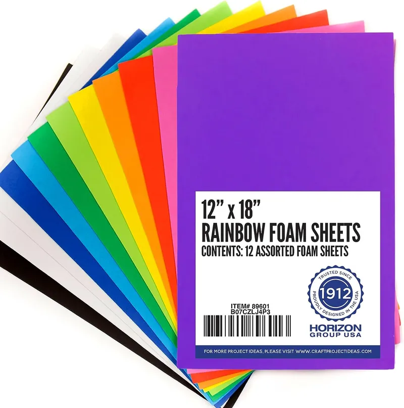
Currently I’ve printed all the parts, and I am already in possession of some 12" x 18" craft foam* that I will be using as “faux bristles,” and also I’m waiting on arrival of a couple of recently ordered items, including a 2.5" flex hose* (of which only 115 mm is needed for this), some 2-1/2 Inch Key Hose Clamps (two of them to attach the hose), and a 100mm MGN12 linear guide with MGN12H bearing slide block*.
If you would like to help test this approach, please feel free to print, assemble and try it out.
About bristles:
There are at least three ways to create “bristles” (real or faux):
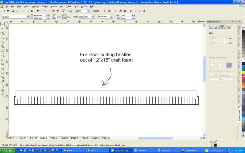
- EVA craft foam cut into a strip and notched to have “bristles” — see attached cut file.
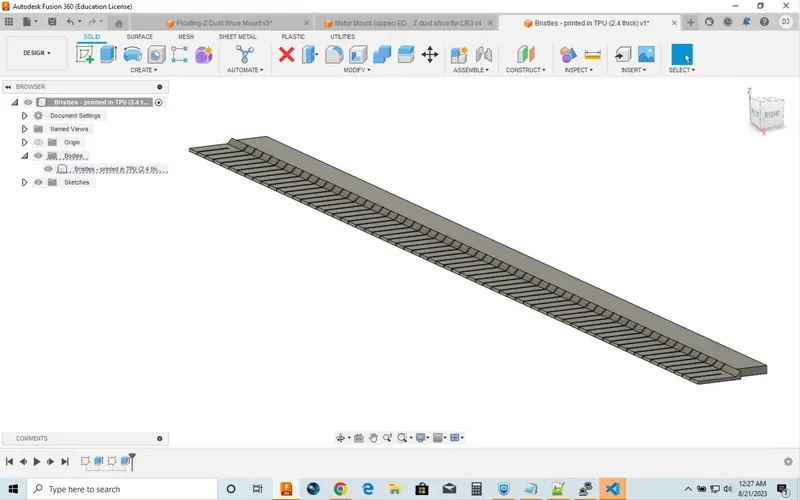
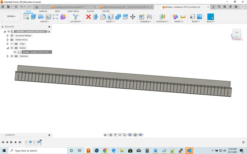
- Printed TPU bristles — see attached print file.
- Buying an actual dust shoe brush (an item made for CNC makers) — not ideal for this, see below, including a purchase link.
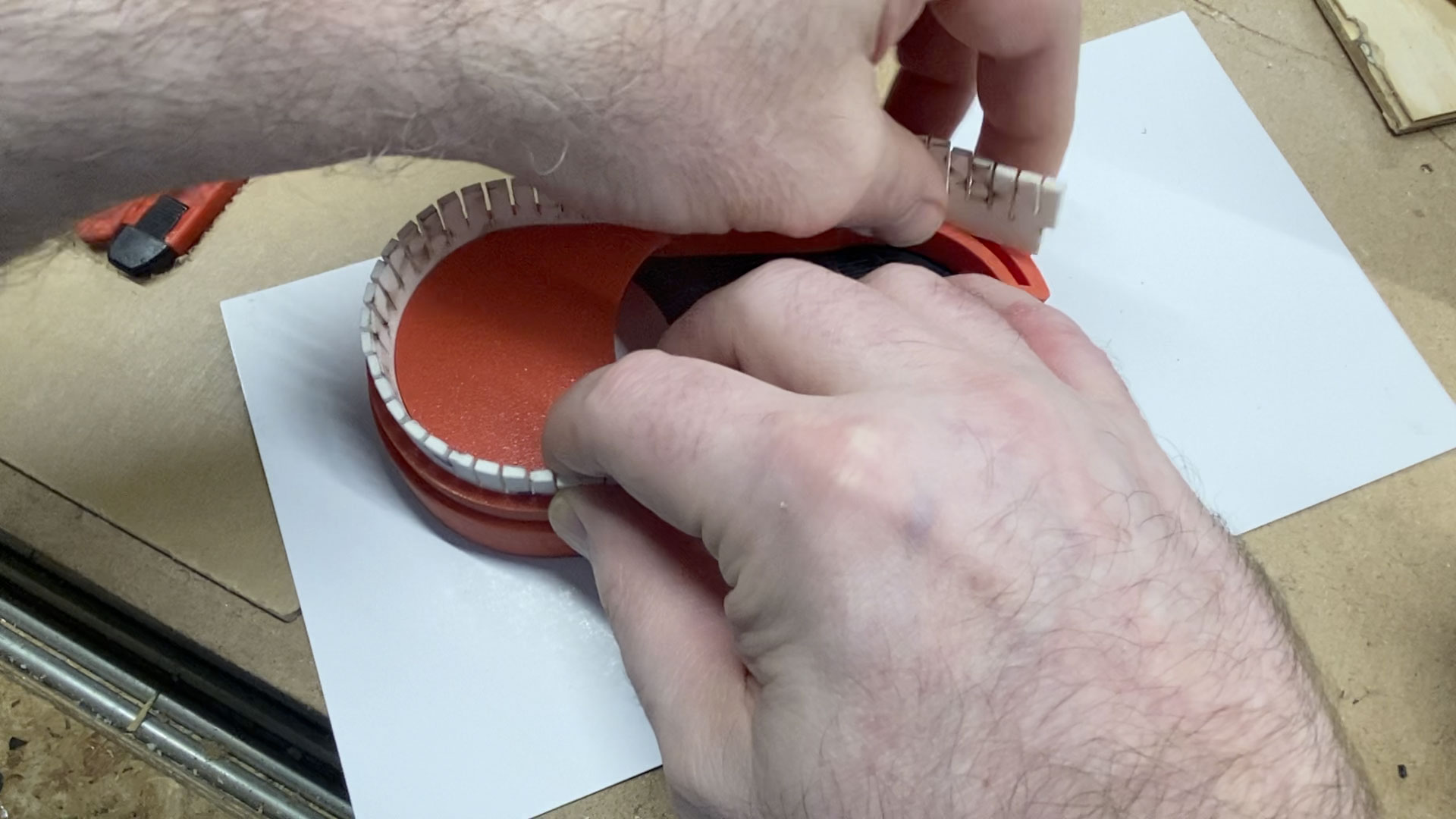
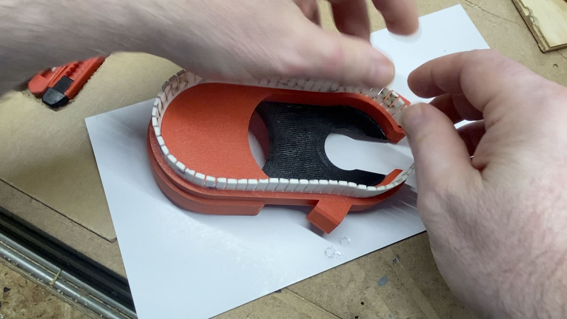
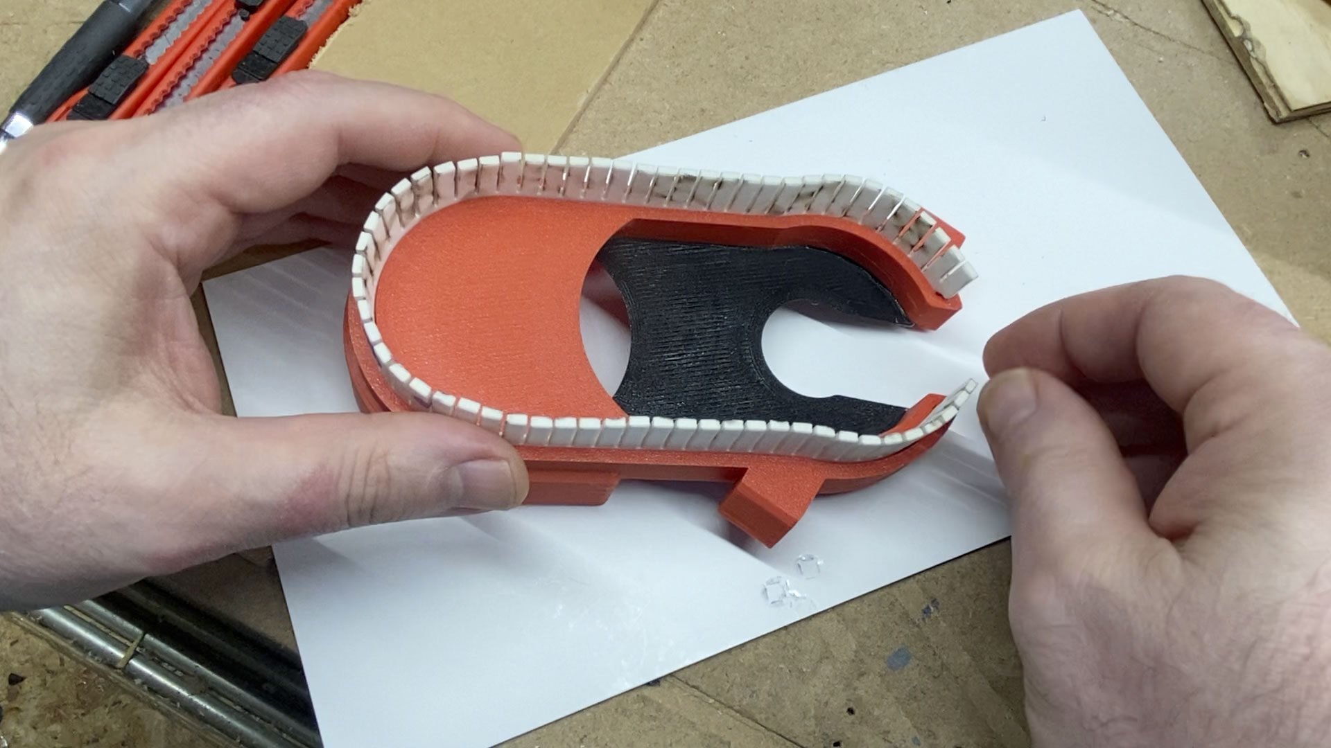
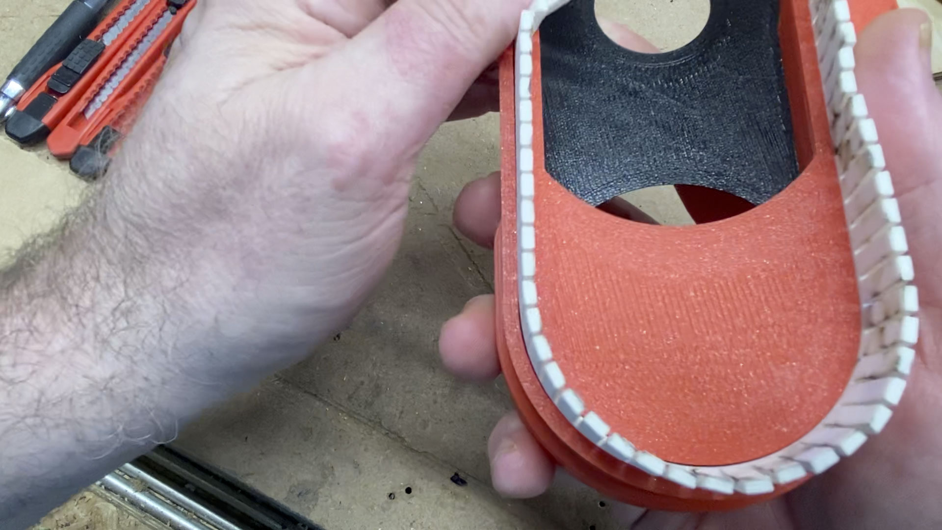
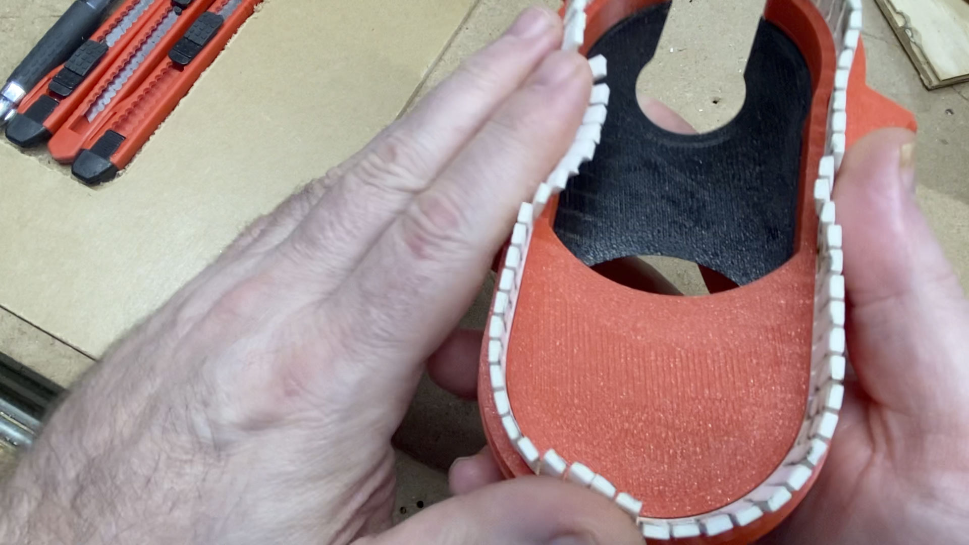
Whichever option you choose, the “bristles” are to be inserted into a groove on the bottom of the dust shoe. This groove is 10mm deep, 3.2mm wide, and ~317mm long.
Below are some details on all three options. I’m leaning toward doing EVA craft foam first, and if that fails, then I will try printed TPU bristles.
Needed items (to be ordered if you don’t have on hand):
- 12" x 18" EVA craft foam* to be used for “faux bristles” — The craft foam linked here is about 2.33mm thick. A strip of it that’s been cut to 317mm (12.48") in length (or up to ~322.4mm if you want to have little extensions on the ends to help close the gap), and in width anywhere from 24mm (just under 1") to 30mm (approx. 1-1/8") or 32mm (approx. 1-¼") should serve. My plan is to insert it with perhaps a little rubber cement added to help hold it in. I’m planning to laser cut mine (cutting the main profile and slits in the same job) using the attached cut file (see below). Or, you could manually cut a strip with no slits, and once it’s inserted into the shoe, it can have the slits cut in it with scissors to create the flexible “bristles.”
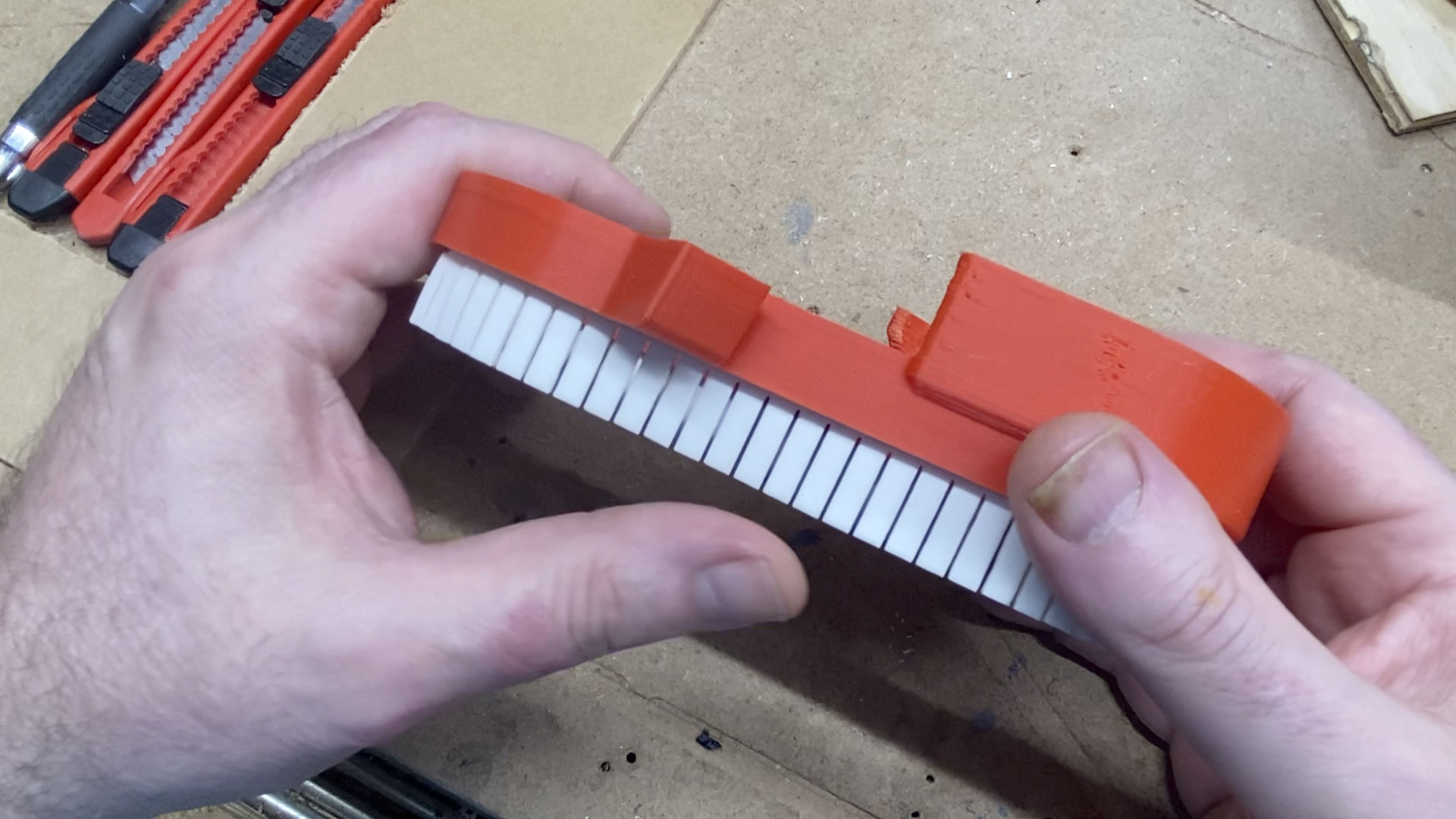
- Alternatively, you can print bristles in TPU, using the attached STL file. If the TPU is too stiff, the “teeth” of the “comb” can be made thinner for more flexibility. The thickness of the inserted part of the file is 2.4mm. The thickness of the “teeth” (bristles) is 0.9mm.
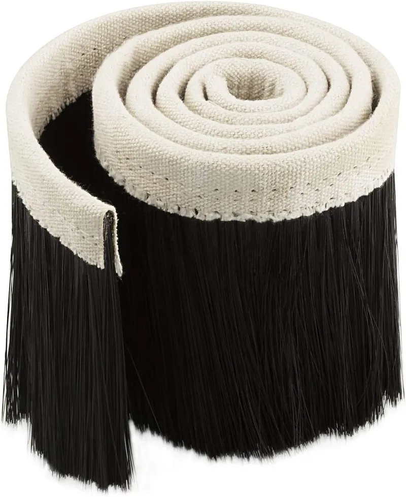
- Alternatively, you could buy a dust shoe brush* and use its bristles. If the base of the brush strip is too thick to go into the groove, you could cut bristles and epoxy them into the groove. I don’t plan on going this route. PS: I had previously bought the one linked here, and its brush strip is too thick to fit into the groove. It’s about 5.33mm wide at the white part of its “base” — and the groove on the printed dust shoe is only 3.2mm wide. Again, my current thinking is I won’t be using actual bristles like this.
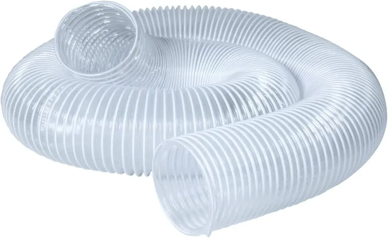
- 115 mm worth of a 2.5" flex hose* — this needs to be able to “compress” down to a minimum length of about 64.3mm when the floating-Z is maxed upwards, and “expand” out to about 115 mm when it’s maxed downwards. I’m hopeful this one (linked) can contract that much, although I don’t have the hose in my hands yet.
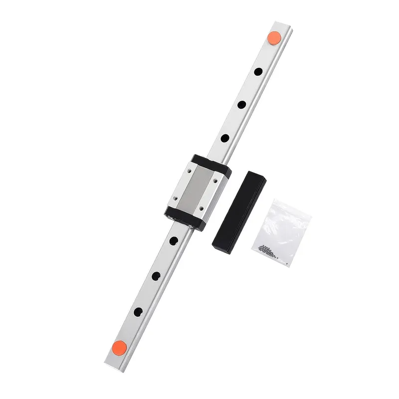
- 100mm MGN12 linear guide with MGN12H bearing slide block* (photo shown is a stock pic of a longer one). If you have a longer one, and have a grinding wheel to cut 100mm off it, you could do that. Here are two alternate listings in case the first one is unavailable: alternate listing #1, and alternate listing #2.
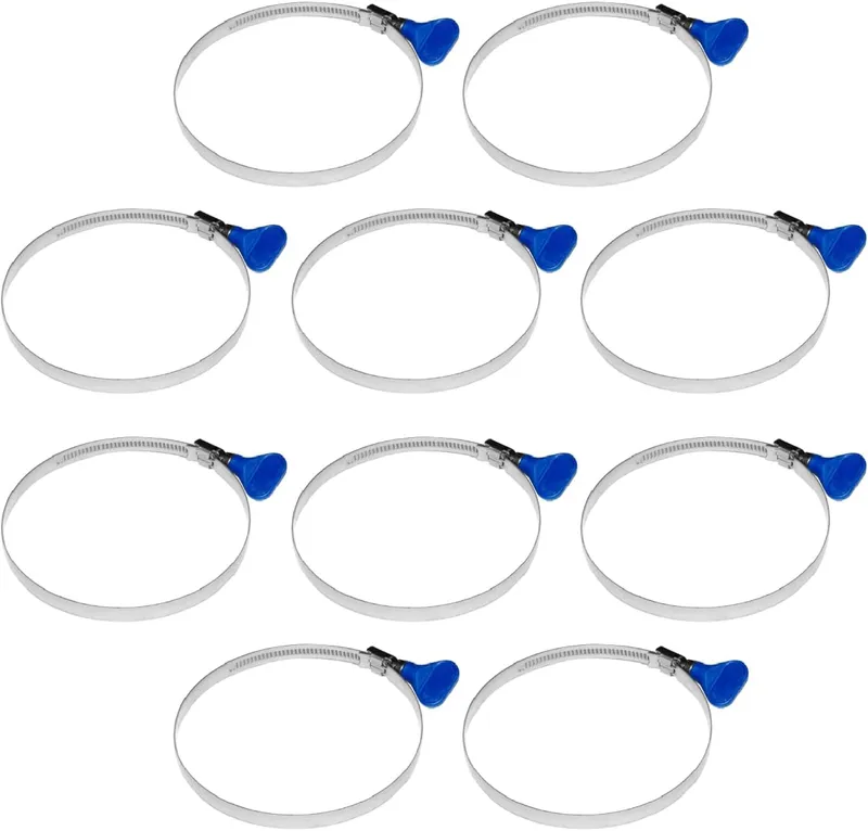
- Two 2-½" hose clamps (I like the “key” kind such as these below) to clamp the hose to the hose mounts.
Hardware note(s) - linear guide:
For strength, ease of sourcing, and familiarity, I chose to go with the very same MGN12 linear guide and MGN12H slide bearing used for the LowRider v3 standard side assemblies. This could be remixed to work with MGN9, and that may well be sufficient. Price difference between MGN12 and MGN9 seems negligible, so went with the better MGN12.
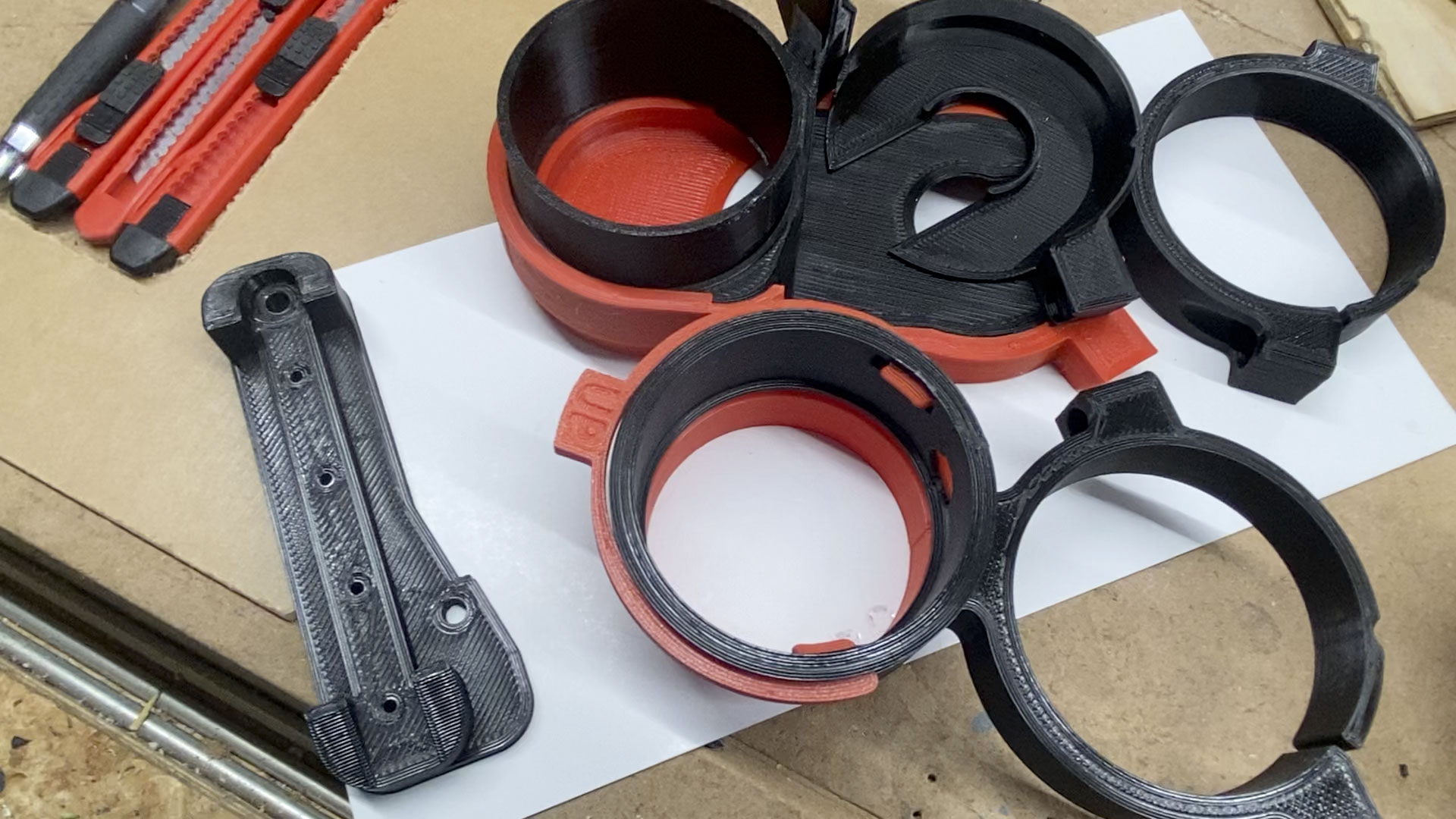
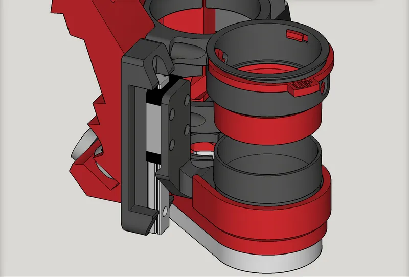
Here’s an overview. This illustration does not show the flex hose, that would span between the top hose mount (colored red here) and the bottom hose mount (colored black here). Also, the EVA craft foam is shown here by a 3D model stand-in that is gray colored (slits not illustrated):
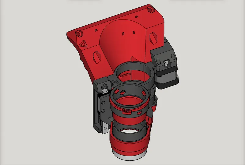
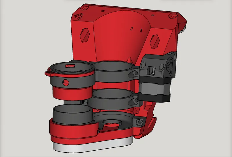
Yet another couple of overview images:
Functionality notes and choices:
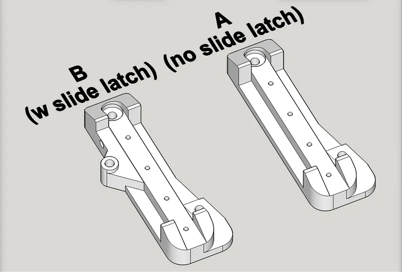
To latch or not to latch:
One of the things I kept in mind is the want of a way to temporarily clip the floating-Z rig at max height while working on bit changes etc. One option is a printed bar with magnets in it, to stick to the linear guide and hold up the slide bearing. However, that will need to be parked elsewhere most of the time and becomes something else to keep up with. So, I thought about an attached latch (see below).
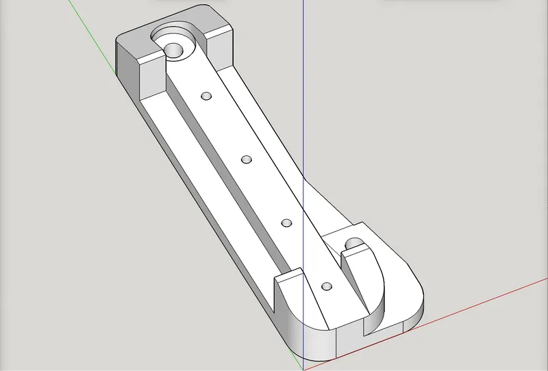
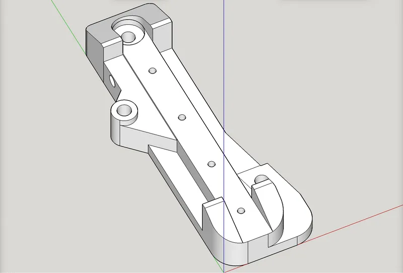
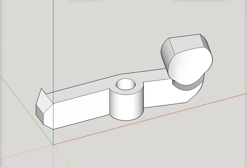
Consider my original floating-Z plan, compared here with one modified to add a “slide latch,” which is spring powered by a spring from a common retractable writing pen. The plan is to use a bolt, M5-30mm, as the “hinge pin” on the latch.
One thing I won’t know until this is tried out, is whether the free motion of the floating Z would be hindered too much by the clip pressing slightly against the slide bearing as it moves up during a job. More soon. Did I mention that testers are needed?
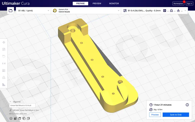
Original — Linear Rail Mount v1.0-A
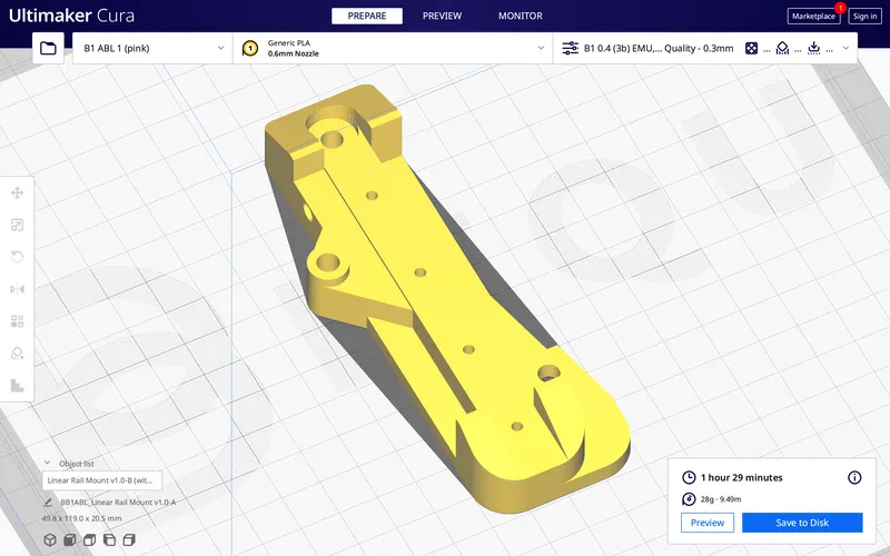
Modified — Linear Rail Mount v1.0-B (with slide latch)

Here’s a side-by-side comparison of the two options for the Linear Rail Mount:
To constrict or not constrict:
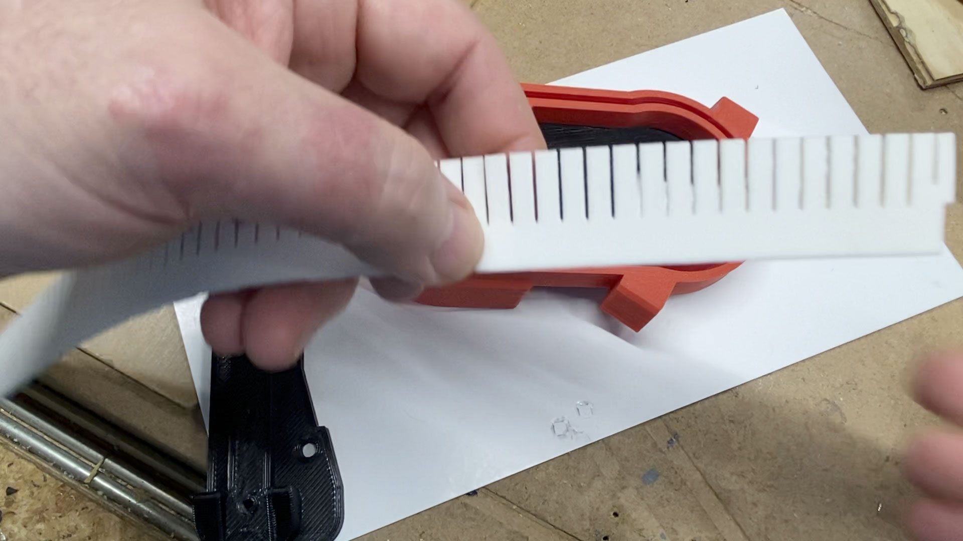
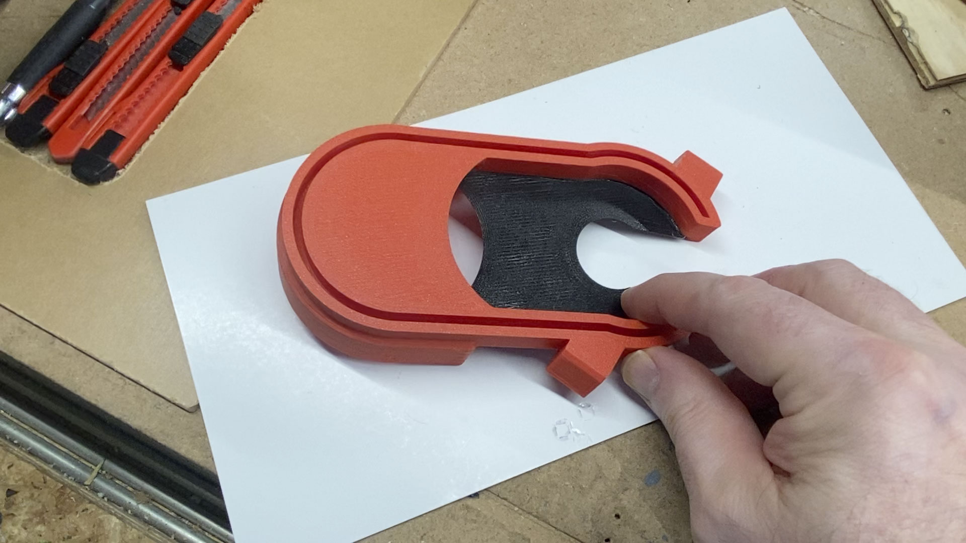
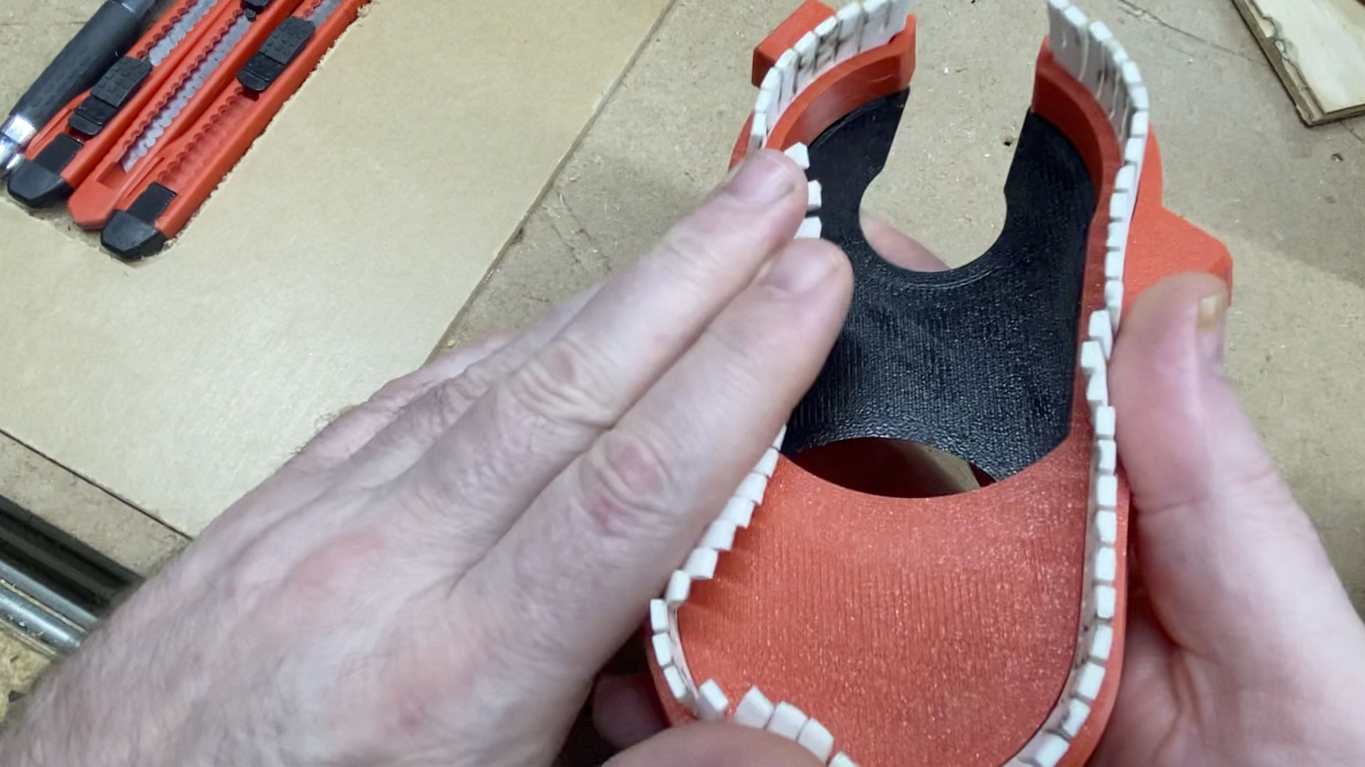
After I printed out a prototype of the slide-on shoe, I decided, given the bristles (either EVA craft foam or printed TPU), it might work better with the opening at the “bend” being less constricted, perhaps even fully open. So, I’ve made three options for testing. I’m calling option “A” as “¼ open,” option “B” as “½ open,” and option “C” as “full open.” If you are willing to spend some PLA on helping test, I welcome your input. Did I mention that testers are needed?
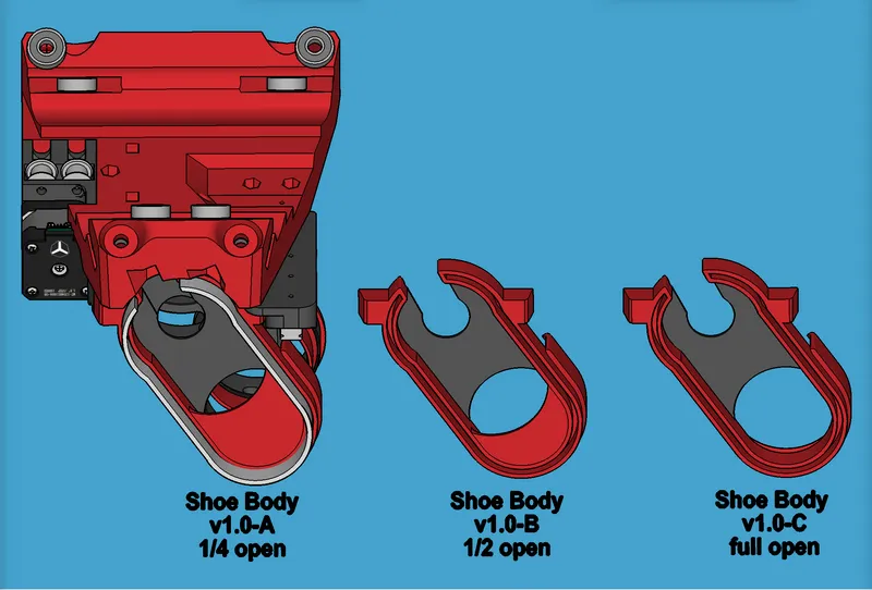
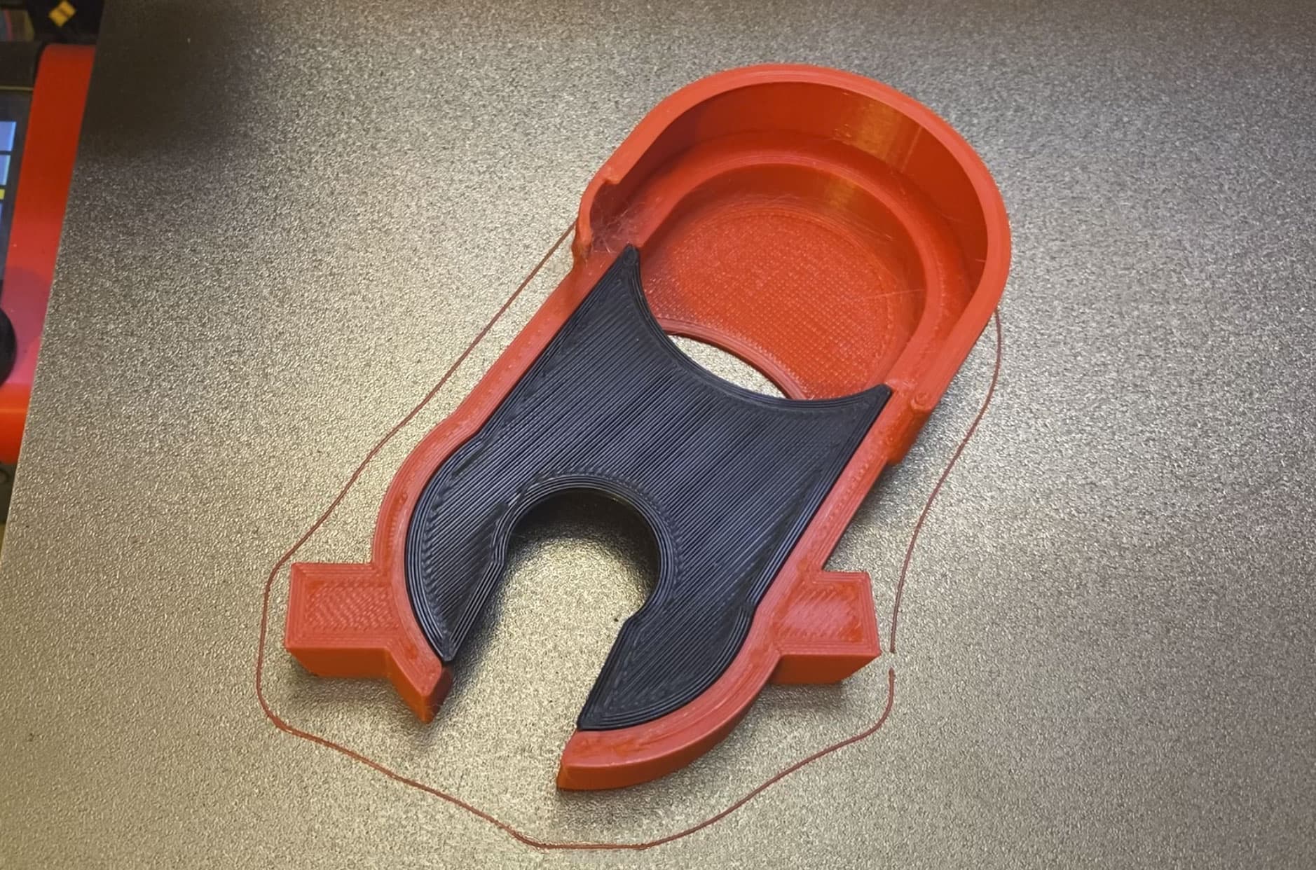
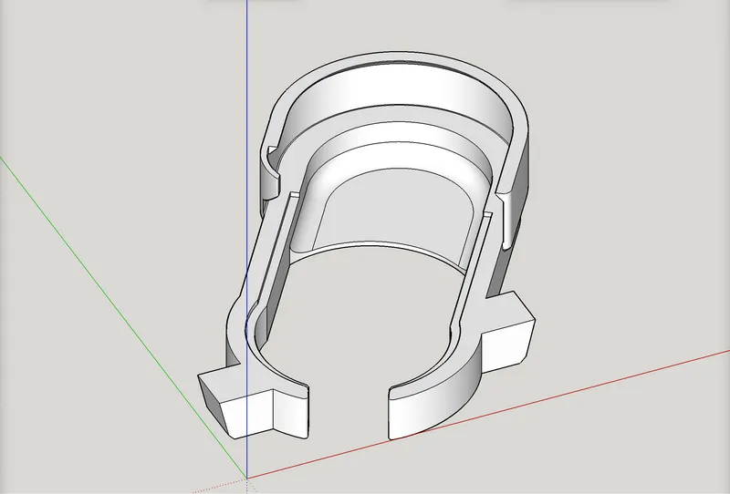
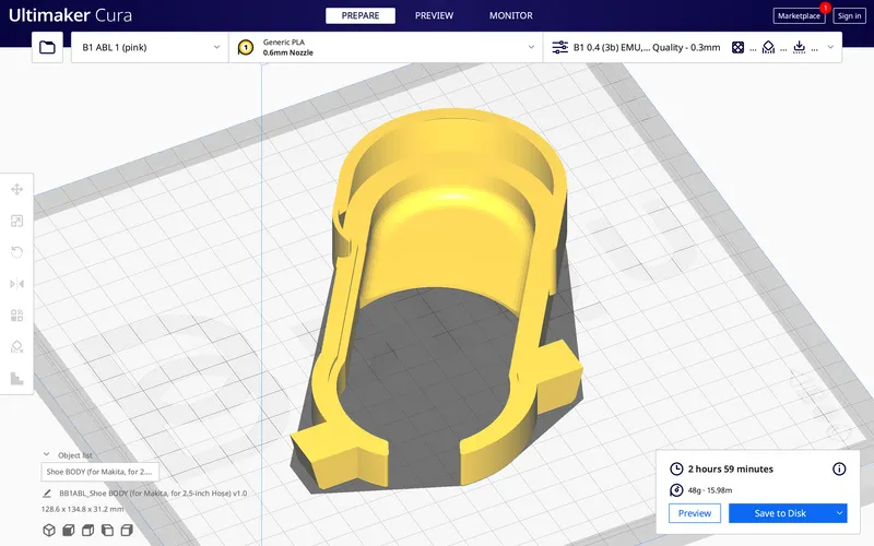
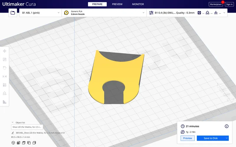
Here are screen shots of the shoe and its lid. I made the lid a separate print to avoid a chunk of support material waste, and to avoid the headache of having to pry the support material off. These illustrations are of option “A” (¼ open).
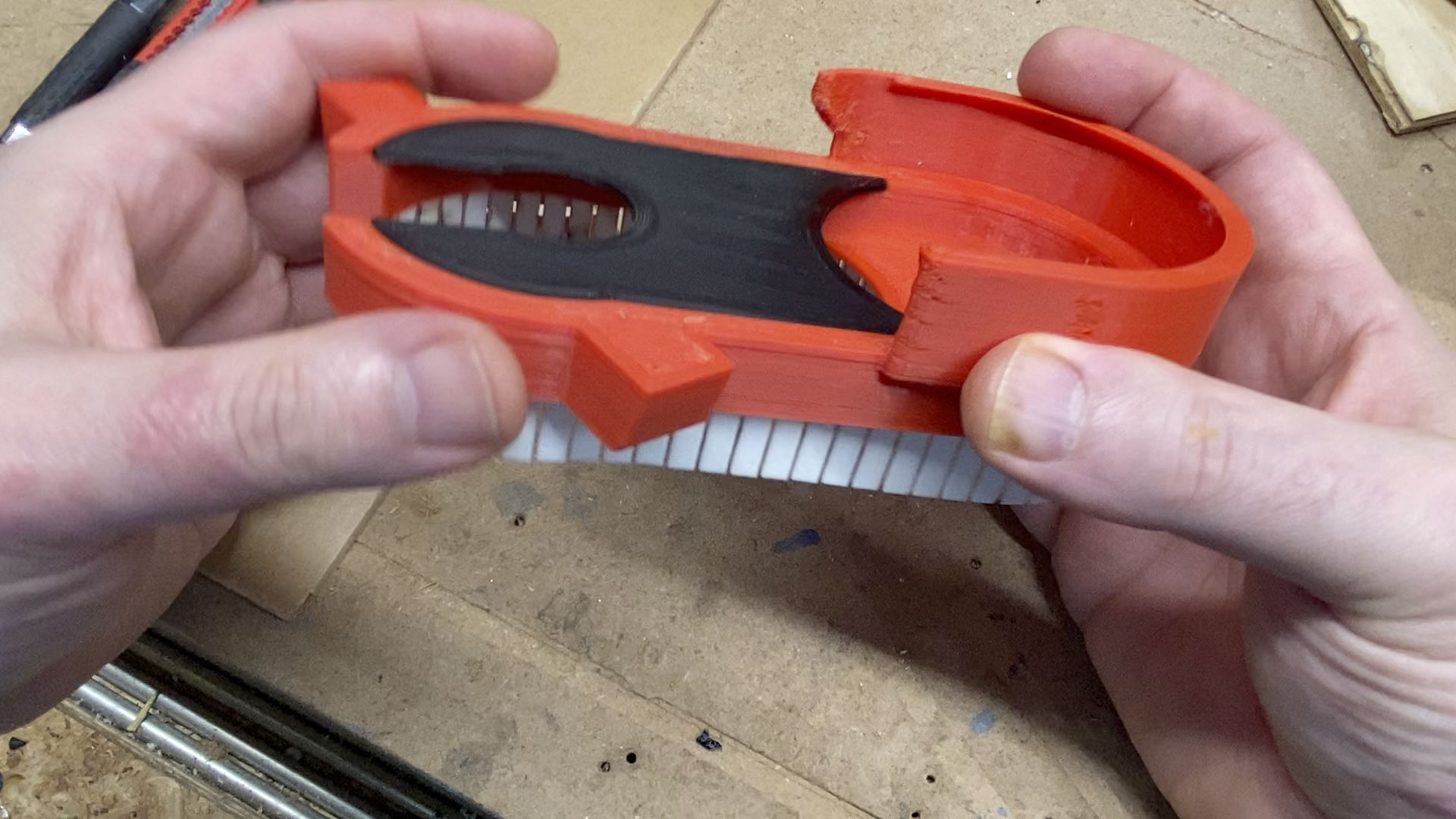
Shoe (option A, ¼ open):
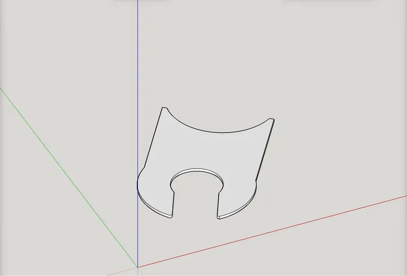
Lid:
Body with lid in place (I used CA glue to attach it):
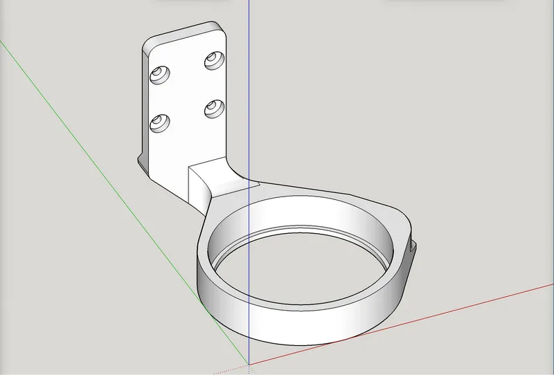
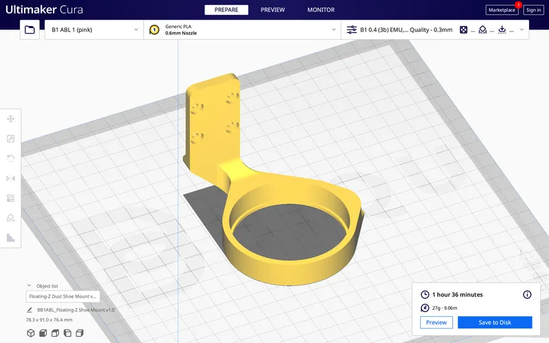
Here is the printed part that attaches to the slide bearing, and lets the shoe be slipped onto it. I named it “Floating-Z Shoe Mount.” It also gets the Hose Mount Lower attached to it. I used CA glue to attach the Hose Mount Lower.
Here’s the Linear-Rail-MOUNT-A (with built-in slider travel stops, but no slide latch) —
For installation, you should have the slide bearing truck already slid onto the linear guide before mounting the linear guide to the printed part; the bearing slide truck can be slid to either end to allow reaching all the screws for the linear guide (I think):
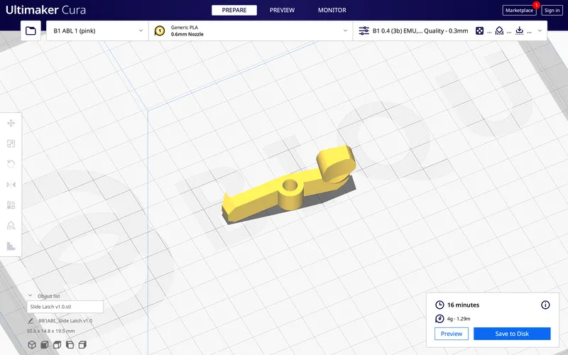
If you feel like testing the slide latch version, here it is:
And for that option you’ll need the Slide Latch (see below).
Note that the spring from a common retractable writing pen has a place here. There is a deep hole for the spring on the Linear Rail Mount (B option), and the part of the spring “sticking out” from there has a corresponding shallower hole on the latch’s knob. Put the latch onto the protruding part of the spring and then use an M5 x 30mm screw to attach the latch to the mount. There is space for an M5 washer (or 2?) between the latch and linear mount.
Slide Latch
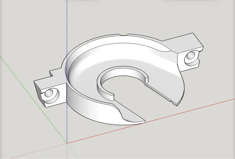
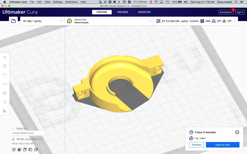
Whichever Linear Rail Mount you choose, it gets installed at the same time as when this Router Shield part below does. The Router Shield uses the existing two screw holes on the LR3 core that are for a dust shoe (same screws you already have there). The Linear Rail Mount shares one of the those screws at its bottom, and uses another one at its top, in a screw hole already present on the LR3 core, but seldom used.
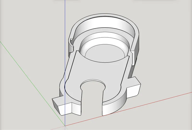
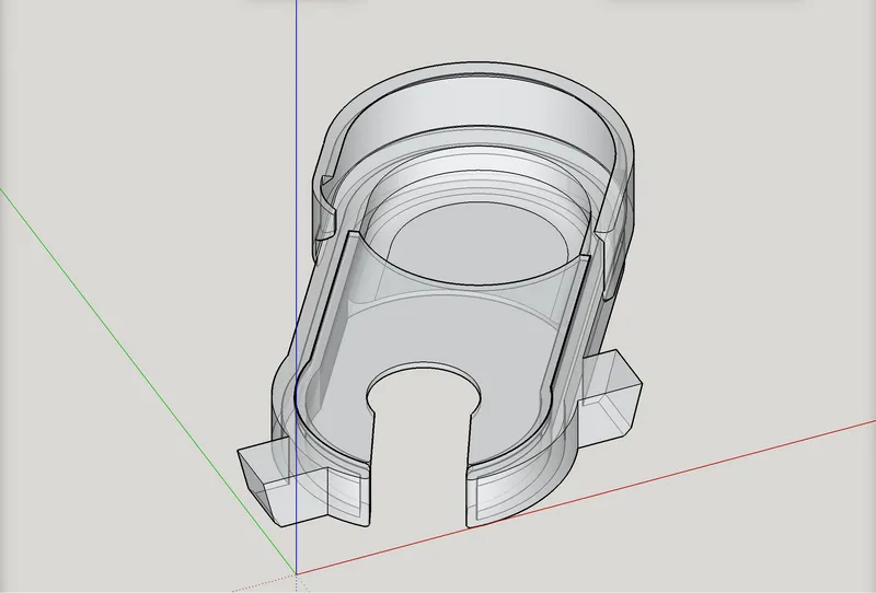
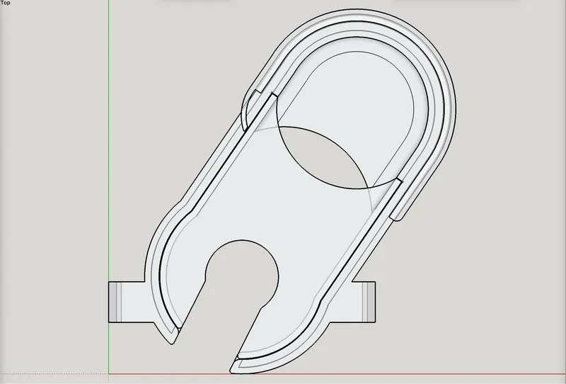
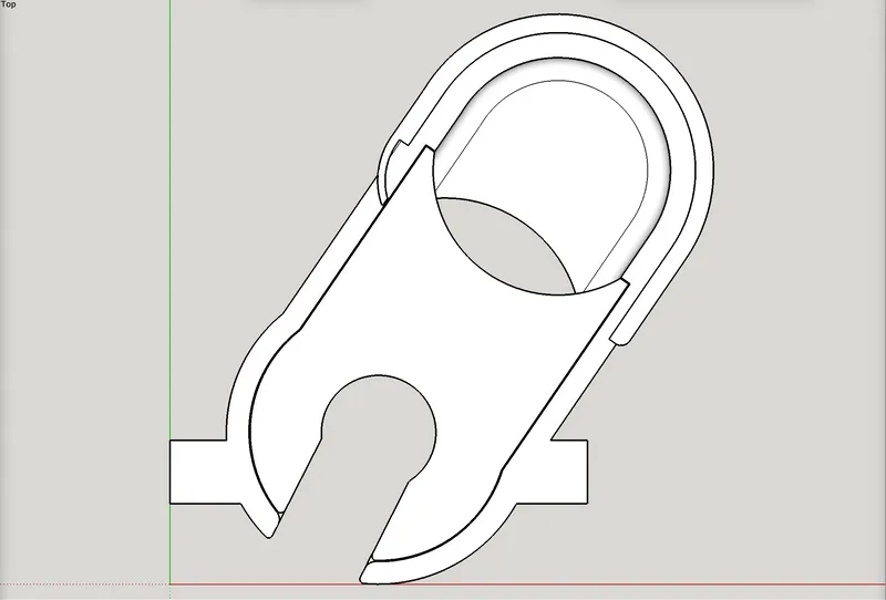
Router Shield:
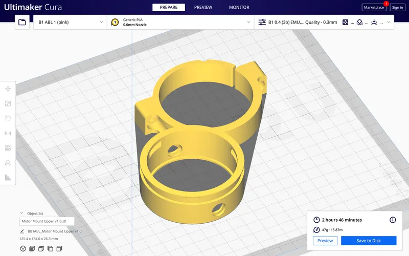
Motor Mount Upper:
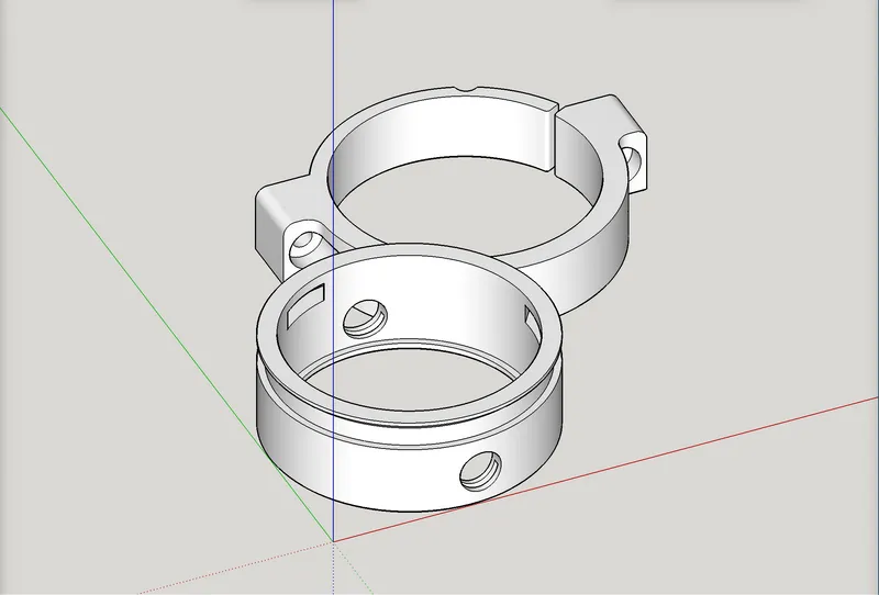
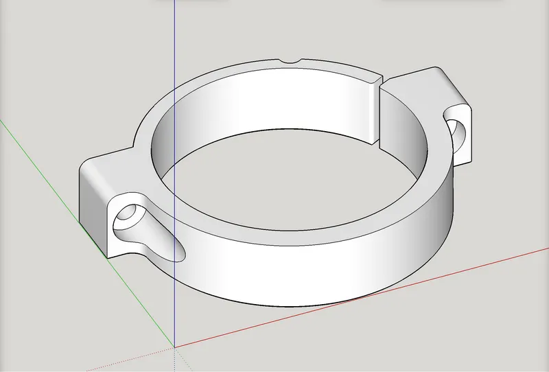
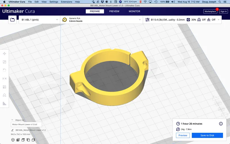
Motor Mount Lower:
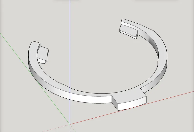
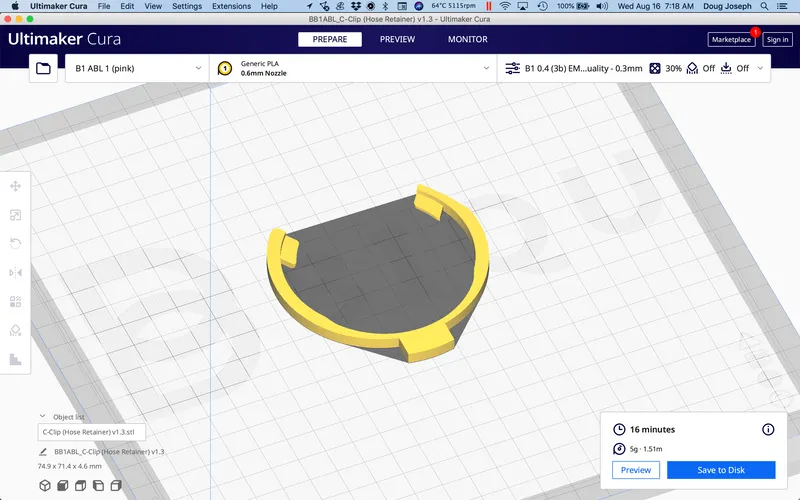
Motor Mount Upper C-Clip (Hose Retainer):
Hose Mounts / assembly notes:
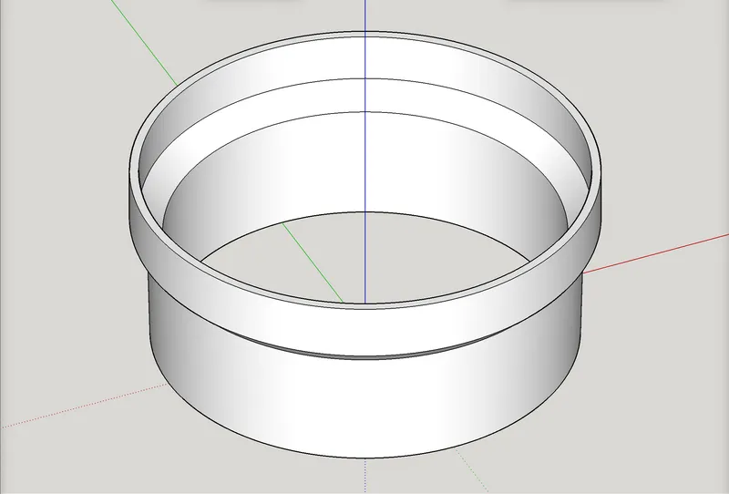
The Hose Mount Upper part was a tight press fit. It gets inserted into the Motor Mount Upper. I did not use glue on this one. The fit seems tight enough that glue may not be needed. Keeping it “straight” as it is headed in, is helpful.
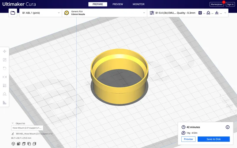
Hose Mount (2.5") (upper)
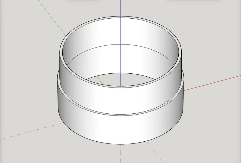
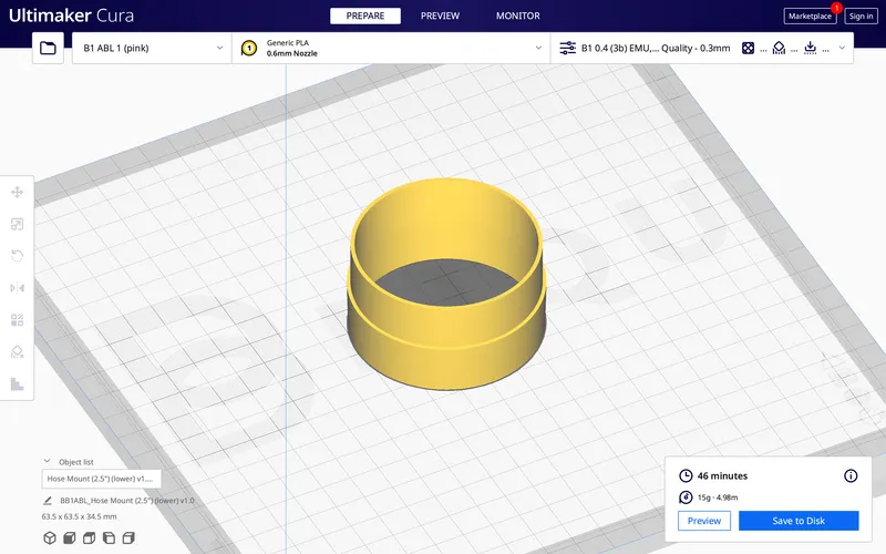
The Hose Mount Lower gets inserted into the Floating-Z Dust Shoe Mount. This one does require glue. I used CA glue to attach the Hose Mount Lower.
Hose Mount (2.5") (lower)
Change log:
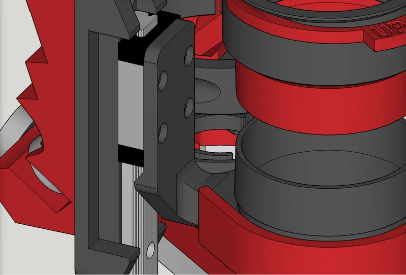
- August 31, 2023 — Revised the “Linear Rail Mount v1.0-B (with slide latch).stl” part such that the Latch is now positioned 0.7mm away from the MGN12H bearing slide. Thanks and kudos again to V1E forum member Alex Eversmeyer (@aeversme) for his early testing and for catching a rub here.
- August 31, 2023 — Thanks and kudos to V1E forum member Alex Eversmeyer (@aeversme) for his early testing and for catching a collision that I had missed, as discussed here. If you previously printed any of the new fixed parts listed below, you will need to reprint them. The new fixed parts, now uploaded, include:
- Linear Rail Mount v1.0-A.stl
- Linear Rail Mount v1.0-B (with slide latch).stl
- Shoe BODY (for Makita, for 2.5-inch Hose) (qtr open) v1.0-A.stl
- Shoe BODY (for Makita, for 2.5-inch Hose) (half open) v1.0-B.stl
- Shoe BODY (for Makita, for 2.5-inch Hose) (full open) v1.0-C.stl
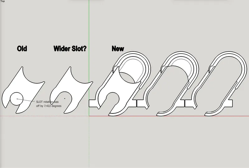
- August 30, 2023 — made slight improvement to the shoe BODY and shoe LID parts. The angle of the slot at the front was off by 7.422 degrees. This dates back to my earliest remix of the shoe, when I made a 2.5" hose option, based on Ryan’s. His slot was straight inline with the shoe body. In my newness to the LowRider v3, I thought I needed to maintain the same slot angle as his, while I also needed to change the overall angle of my larger shoe design. Now much later, I am convinced there was no need to leave the slot at the same angle, and this realignment should provide ever so slight improvement of inserting and removing the shoe. The change is so minor that there is no need to reprint if you already printed these two parts. I won’t reprint for this alone. The change affected all three variations of the shoe: qtr open, half open, and full open.
- August 24, 2023 — added these missing parts that should have been in the first release. Oops. Now they’re here.
- “Router Shield v1.0.stl”
- “Shoe BODY (for Makita, for 2.5-inch Hose) (half open) v1.0-B.stl”
- “Shoe BODY (for Makita, for 2.5-inch Hose) (full open) v1.0-C.stl”
- August 23, 2023 — initial release.
My PayPal tip jar: https://paypal.me/design8studio
Various LowRider 3 CNC remixes:
View all my models and remixes on Printables:
*affiliate links to Amazon items
