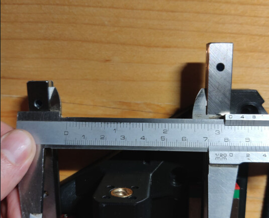
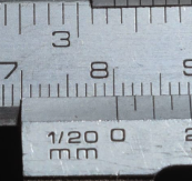
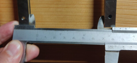
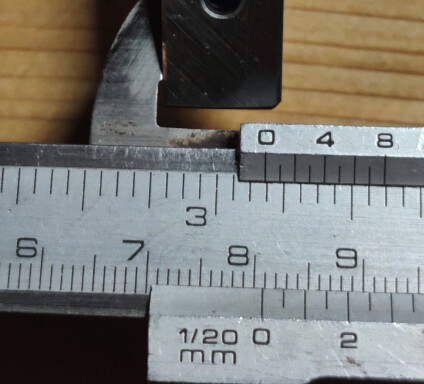
I’m assembling the XZ plates at the moment and found out (as instructed) that my parallel rails aren’t parallel. They have 1mm difference in the maximums (top compared to the bottom) which I think is not tolerable.
How can I troubleshoot this or do something with it?
I put the linear rails next to each other and tested the gaps. They seem to be fine.
So it must be the 3D print? I printed it on the Prusa Mini+.
You printed the YZ plate? I don’t think it could possibly be that far off.
There are some tips in the instructions. Start with loose screws into the bearing blocks and into the YZ plate. Tighten them up one at a time always checking the full range of motion. There is plenty of room for them to move and be parallel. The crews into the YZ plate through the rails have lots of room to move.
The only time that goes wrong is if you have a bad screw and the head is off center and moves the rail around, you can just get rid of it and go one screw less.
It’s the smaller piece that i’m concerned about - XZ - with the brass nut attached to it.
Does your advice apply still? Because you mentioned in the instruction to check for parallel of the linear rails but I couldn’t find any information if they aren’t parallel.
If you linear bearing rails are fine, don’t mess with them. Your previous statements are a little unclear.
The Z stub? If that is not correct, you can upload a picture of the part or use the file section to get the name of the actual part you are having an issue with.
If it is the Z stub you can twist it on the screw to line it up, if it is too far out you can sand down the mating face a little if you need too.
I did as instructed and when the screws on the XZ plate are loose, it works smoothly. When I snug them, it’s very tight and moves with a lot of friction.
I have noticed that the XZ plates are probably cupped from the printing, as if it would move the top direction from the print bed.
Do I reprint them? Most likely… right? When I use higher bed temp, will it stick better?
Yeah, try reprinting them. Warping could be too hot or too cold of a bed, bad adhesion, extruder temps, room temp, it can be a tough one to figure out.
I did reprint it today, in a improvised sort of enclosure. Did set up a first layer again just to be sure. The adhesion was fine, the print looks good. But it is still warped. It has slight concave shape and of course it doesn’t let the piece move freely on the rails.
So I am thinking how to solve this. I think the best option will be to let someone mill the XZ plate locally which I wanted to avoid due to the cost.
If anyone has some sort of potential solution - I’m listening.
This is actually very good question. I don’t remember how I did it back with the first XZ prints back in February.
But I did pull the print pretty soon after the print today. I was having the other part printing and stopped it like 2hrs in, to not waste any more material. And as I removed it from the bed I noticed how the temperature influences the print a lot.
Of course it is noticeable in a thin piece. But then I thought if I might have screwed it up myself in the other prints when I didn’t let it cool enough.
I used printed XZ plates and a two-piece printed YZ plates for my initial build. I had the same issue, where the linear rails were a bit stiff. I also had a lot of flex in the YZ plates, enough that the heel/toe measurement could vary by up to 5 mm.
I ended up having to loosen a couple of the linear rail screws a 1/2 turn to get it to move fairly freely. It wasn’t perfect, and the gantry didn’t always drop when the power went off, but it was enough to get me going.
I used that imperfect build to cut new XZ and YZ plates from 1/4" and 3/8" aluminum. Now the rails slide smoothly, and the gantry drops like a stone on both sides when I kill the power.
I just wonder if you let the parts cool before you remove them from the build plate if they might stay straight. Or at least straighter. I know on my printers if I let it cool I can hear it naturally release from the plate. After that they are good to go.
I won’t lie, there were definitely some challenges, and a few learning moments along the way. But the LR3 worked great, and I gained some valuable experience.
You can check out some of the steps and mis-steps here:
There’s also some more posts a bit later in that thread that talk about cutting the thicker aluminum.
’
The biggest thing that I can suggest is to use a feeds and speeds calculator, and learn about Trochoidal milling. It takes longer to do a single pass, but I was able to get a 10mm DOC so I only needed to do a single cut.
These are the speeds I used for a 1/8" single flute:
Trochoidal: RPM 20000, DOC 2.75 mm, FR 2250mm/min, Plunge 500mm/min, Plunge Angle 90, Trochoidal Stepover 7.9%, Trochoidal Width 35%, Finish 0.35mm YMMV, so do some test cuts first.
(Note DOC varied depending on the material - 2.75 for the struts, 7.0 for the 1/4", and 10.5 for the 3/8")
Note that I also used an air/IPA mist system (Show me your IPA Mister setup - #3 by Bartman)) This is pretty much essential for clearing out the chips from the slot, and for keeping the mill cool and lubricated.