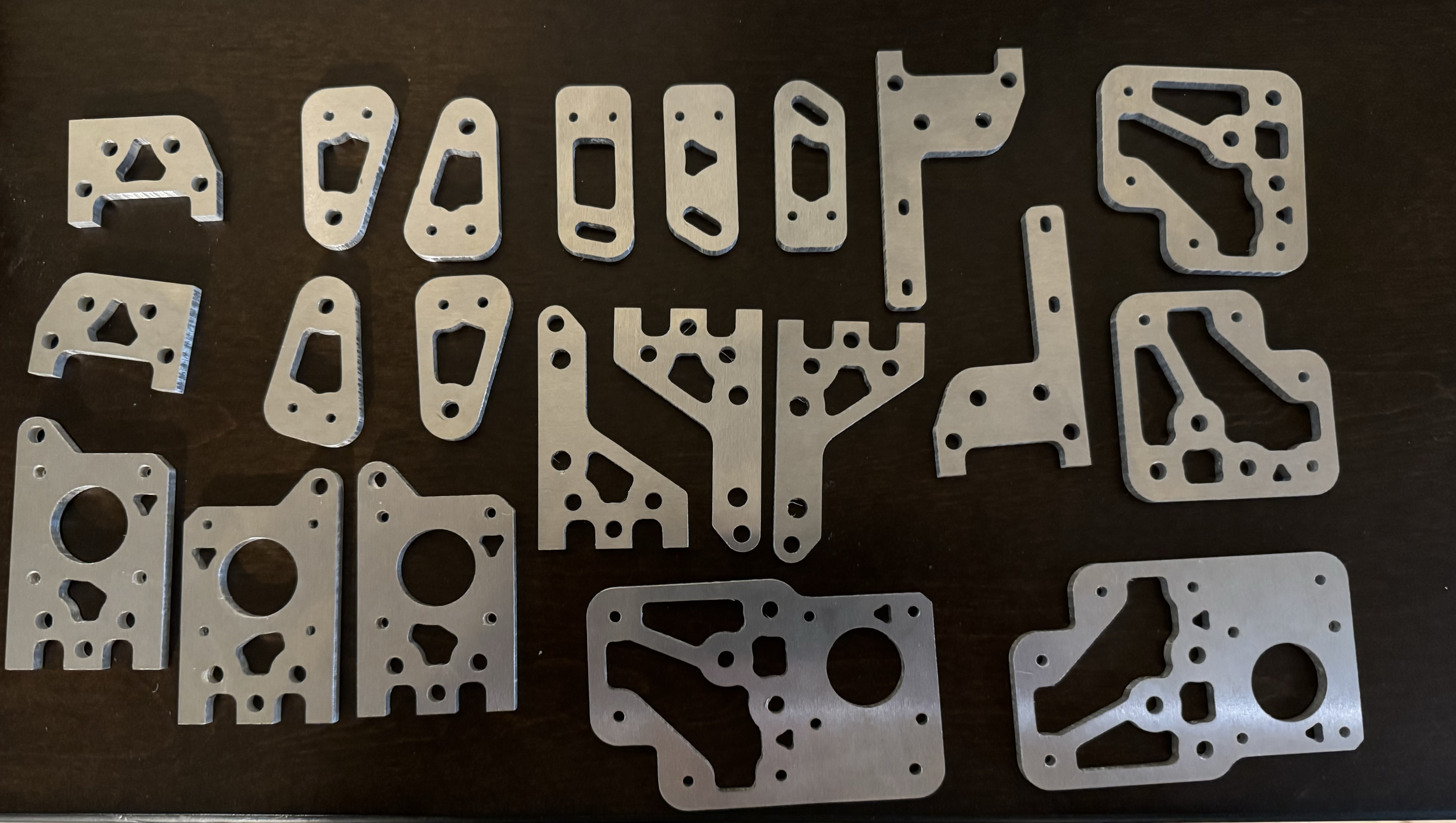
I have just recently embarked on building myself an MP3DP v5 (Forum thread). I decided I would mill the Aluminum plates myself because why not? This is why I built myself a CNC to begin with…I wanted to be able to make things.
My intent here is to detail, as much as I can, how I went from only ever milling MDF, to successfully milling my MP3DP v5 aluminum plates without any major setbacks. There seemed to be some interest in my build thread for some help tackling this job.
!!! Note: Although this all worked for me, there is no guarantee that everything I did will exactly work for you. You still need to do your own tests. My machine is as basic as it gets, so this should be achievable for everyone. If you intend to take some of the advice in this post, please make sure to read EVERYTHING first
My success was made possible with help from @Jonathjon and @vicious1. My goal is to pay it forward and help reduce the barrier of entry for anyone who wants to be able to mill their aluminum printer parts for themselves.
I am not an aluminum milling expert, or even a CNC expert, so please keep that in mind, and if anyone has anything to add below, please do.
My Machine
I have a basic 4’ wide LowRider 3 running the corded Kobalt trim router. Build Thread
I do not have a coolant or air system installed.
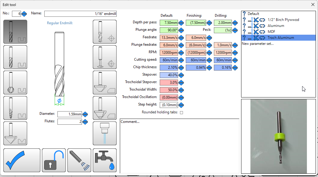
The only bits I used were the 1/8" single flute(this or this) and 1/16" 2 flute(this) end mills from the V1 shop
My Settings
I used EstlCAM V12. Please make sure you are using the latest version, 62 or later, due to some very important bug fixes that will help these settings work correctly.
The settings I used to cut the plates are using trochoidal milling. Trochoidal may not be the best way to do it, and it is absolutely not the fastest. It is, however, very beginner friendly. I think it’s more than 2x slower than normal cutting, but if you are new to milling aluminum (like me), I very much recommend starting here to get a feel for how your machine and bits react to the settings.
Also, if you don’t have coolant or air setup, I think the trochoidal milling can help keep the bit a little cooler. It also might be a bit harder on the machine the way it jerks around.
These settings were taken from @Jonathjon, then I backed off of his settings a bit first and worked up to what I was comfortable with. I suggest anyone else do the same if they take my settings below.
My settings are:
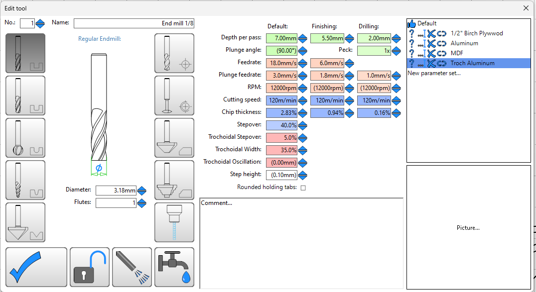
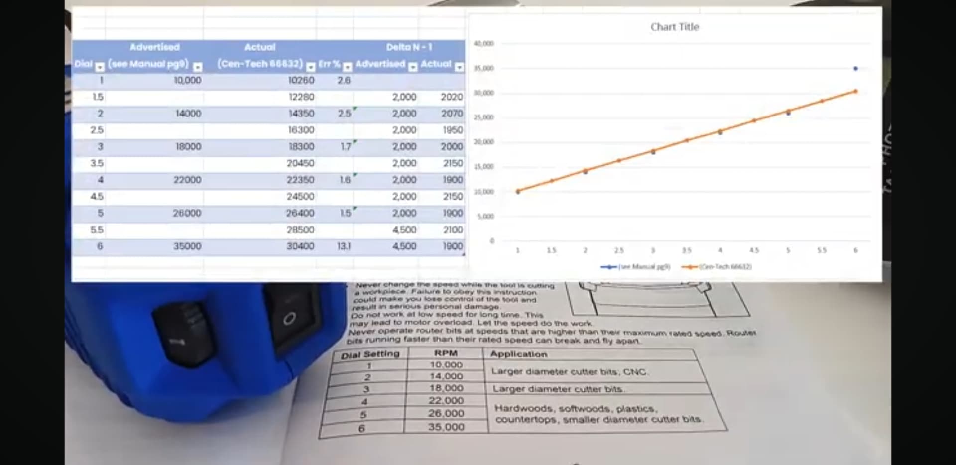
I do not have a speed controller so the RPM settings may not be accurate. By the end, I settled on running at Speed 2 on my Kobalt Router and it seemed to handle it fine. I believe @azab2c has a video somewhere where he tested exactly what speed that should correlate to. Maybe he can link it below.
Also, make sure to include a finishing pass on all of the Hole and Part cuts. This will make sanding afterwards waaaaaay easier.
Stock
I purchased the following 12" x 12", 3/16" thick aluminum plate here
I was able to mill all plates from this one sheet. I don’t think I could have used a smaller sheet. Bigger is fine, but 12"x12" is the minimum amount of area I would attempt to fit it into with these settings
My Setup
I did not want to attempt hours straight of milling aluminum, so I decided I would prep ahead of time, and make sure everything I did was repeatable. I then planned to make CAM programs for one piece at a time to start
So here’s what I did.
- Load 1/16" bit into router
- Home Z, Home X, then Home Y
- Turn on router and Move -Z until bit is just barely cutting 0.5mm or so into the spoil board
- Move +Y200, Move -Y200, Move +X200
- Raise machine and turn off router.
This drew a mounting guide where the bottom left corner was at exactly (100,100) and the edges were exactly square with the motion of my machine. I then mounted the aluminum plate with a screw at each corner. (Read the CAM setup section below before drilling holes)
This meant that no matter what happened, I had a repeatable starting point to be able to continue after mistakes, etc.
Spoiler Alert: This came in handy more than once ![]()
CAM Setup
In EstlCAM, I set up the grid to be 1" (25.4mm) squares so I could easily see and layout all my parts and make sure they fit within the 12"x12" area to be cut.
I chose the following layout:
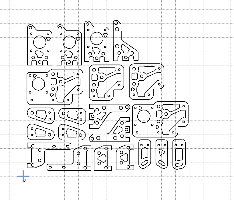
Note: Be sure to add all items before you make your first cut, as EstlCAM will move the Zero point when you add a file. You can also maybe add something into the file that can be used as a reference point in case you lose your Zero point, to be able to easily recover your exact zero from before the add.
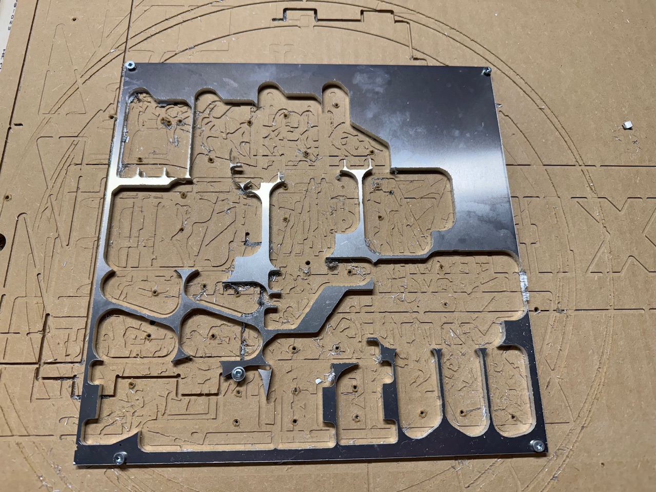
Final sheet after all cuts:
Coolant
I didn’t have any…
So I ran a bit of a manual air assist ![]()
I lowered the PSI on my compressor to around 25 and used that with an air gun to help evacuate chips and cool the bit. Yes, I actually stood there blowing air on it by hand the whole time…
Cam Tips
V1 logos
All of the V1 logos look better when cut with the 1/16" bit. Use a finishing pass.
Holding tabs or not
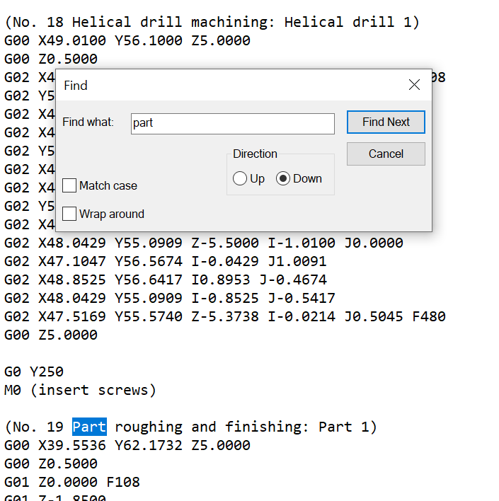
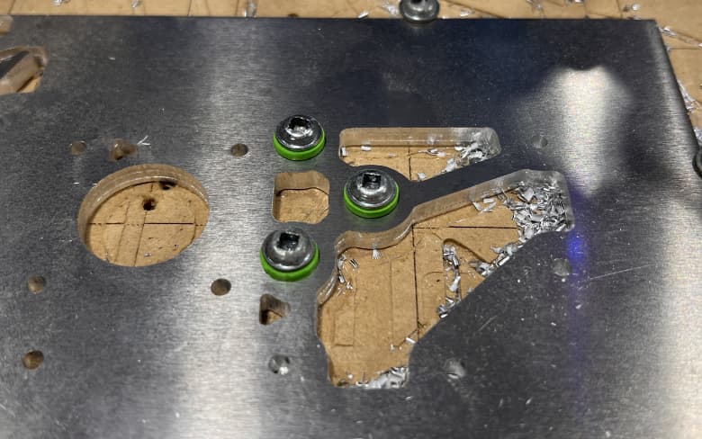
I decided against using holding tabs. Instead I would plan to screw the part down to the bed by pausing the job before it did the final Part cut, and insert screws into holes, making sure that the holes I picked were far enough away to not hit the bit.
Along the way, I also decided to print some screw “cushions” to stop the screw from marring the surface, like this:
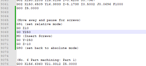
I took a cue from @Jonathjon and instead of trying to manually pause the job, I manually edited the GCode before transferring it to machine, and inserted the following gcode:
(Move away and pause for screws)
G91 (set relative mode)
G0 Z10
G0 Y250
M0 (Insert Screws)
G0 Y-250
G0 Z-10
G90 (set back to absolute mode)
Please test this code before using it on your machine to make sure it works as you expect
Ordering
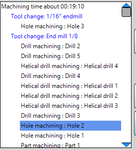
EstlCAM will not automatically order things in the way I wanted, so I manually overrode the order. My preferred ordering was…
- All 1/16" cuts
- 1/8" drill tool paths
- 1/8" holes, smallest to largest
- Part tool paths (these will be last by default)
If you don’t order these yourself, you may end up with extra bit changes
Pauses
I used the Gcode above sometimes multiple times in a program. As I got more comfortable and was making programs that cut for longer, I started using the pause more just to let my machine and bit cool.
So, for instance, after all of the drills, I would insert the pause. Then when the program ran, I would let it pause, turn off the machine, and hit it with some compressed air until the bit was cool to the touch.
For now, this is all I can remember. I will update this post if I think of anything else useful pops into my head.
I hope this is useful to someone and I didn’t leave out anything major. Please ask as many questions as possible and @Jonathjon will answer them all ![]()