Jackpot board install on JL1 laser

Starting a thread to document my work to put the Jackpot onto a JL1 laser.
This will be another typically slow build log for me. Hopefully less slow than my stalled before seriously underway repeat printer log.

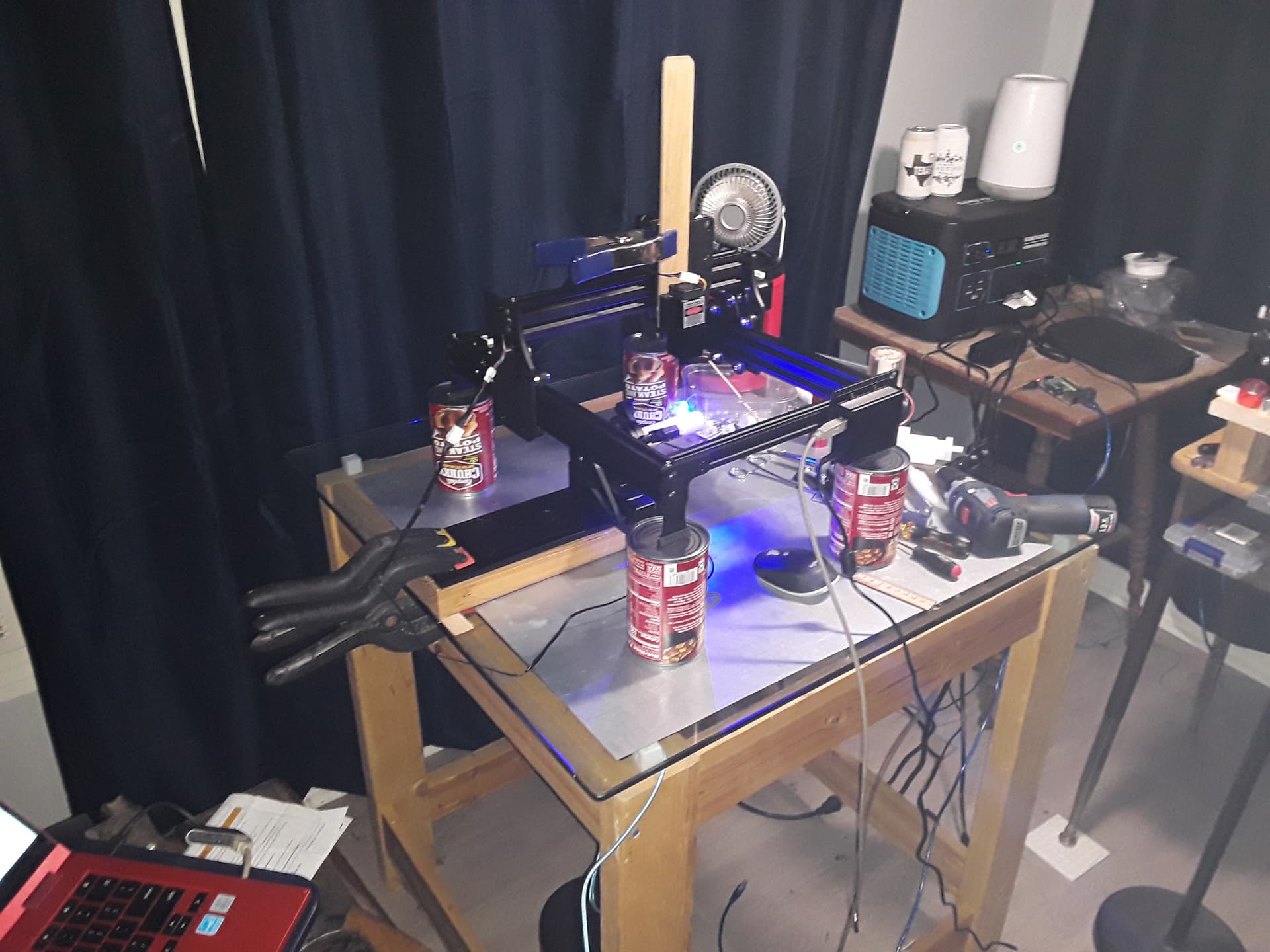
Here’s the JL1 on my too small work surface I’m using at the moment:

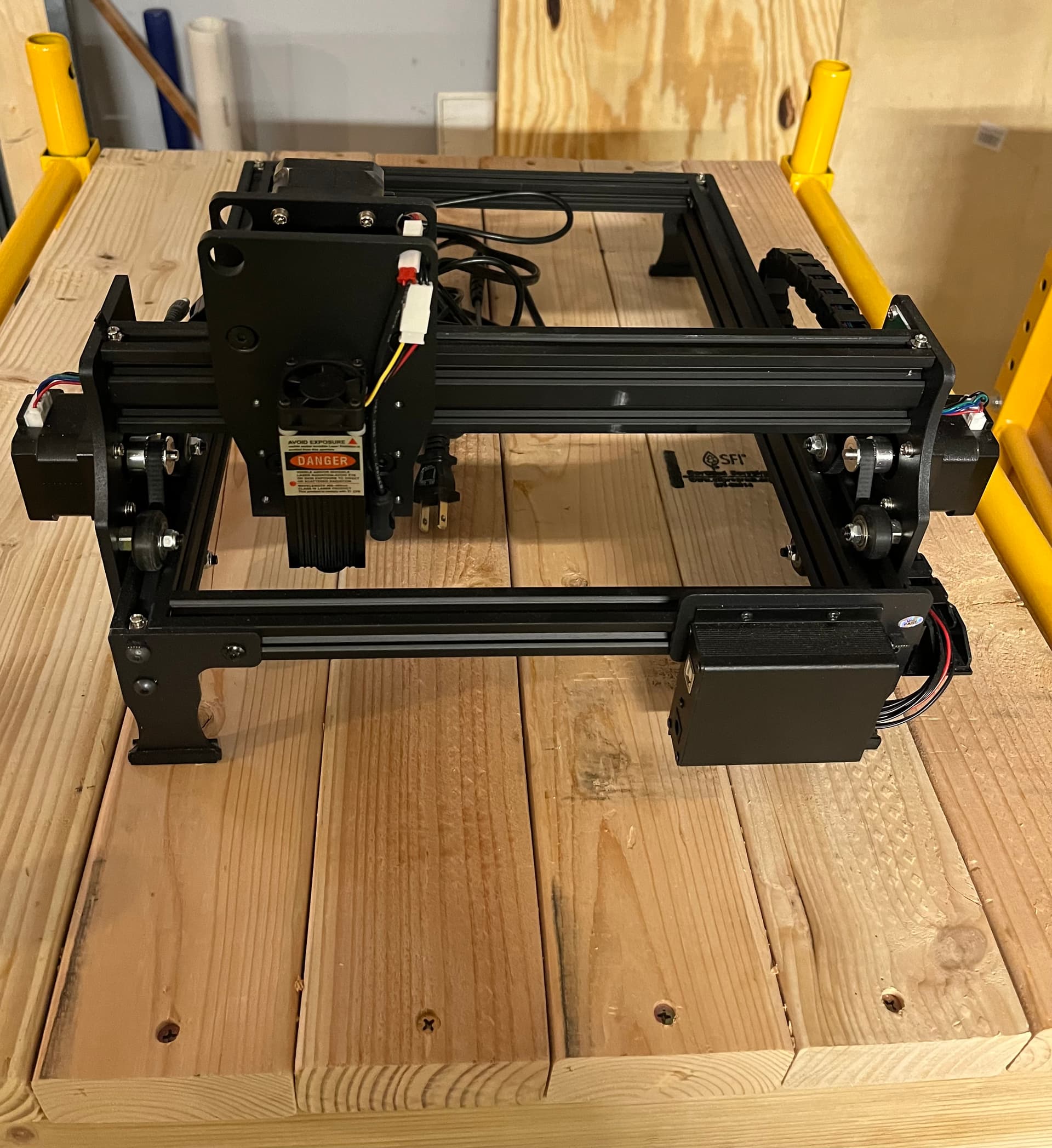
That JL1 was a $75 purchase that our own @dkj4linux pointed out to us in these very forums. How cool of him to tip us off about really affordable hardware like that.

I use Lightburn to drive it from a windows laptop, and I converted the firmware over to GRBL. I have a couple of posts over on the LightBurn forum about that because I was too dumb to follow instructions properly and didn’t hit the reset before trying to flash the firmware update. Ended up needing to get a device programmer and unbrick the thing because of my stupidity- but that worked and it is currently running GRBL on the stock controller.

Just to the left of this setup and not visible in the picture I have an assembly table with a really cheap and crappy scrap plywood and dowel protective enclosure I’m thrashing together as I swore to myself I wouldn’t use the JL1 without better protective provisions than using my own OD 6+ laser safety glasses that I bought to use when occasionally working with lasers at work.

There’s too many chances to have a grandkid wander into the garage and encounter me messing with the laser- so not having an enclosure has also seriously limited my experimenting.

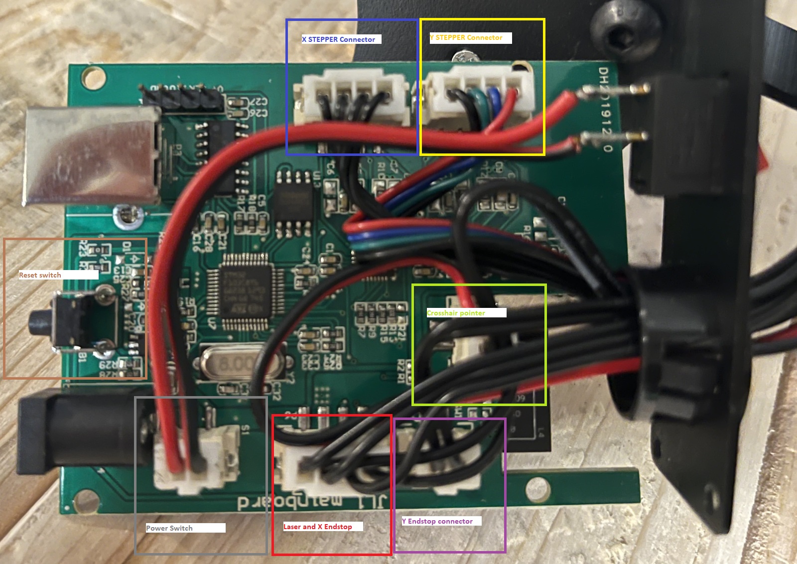
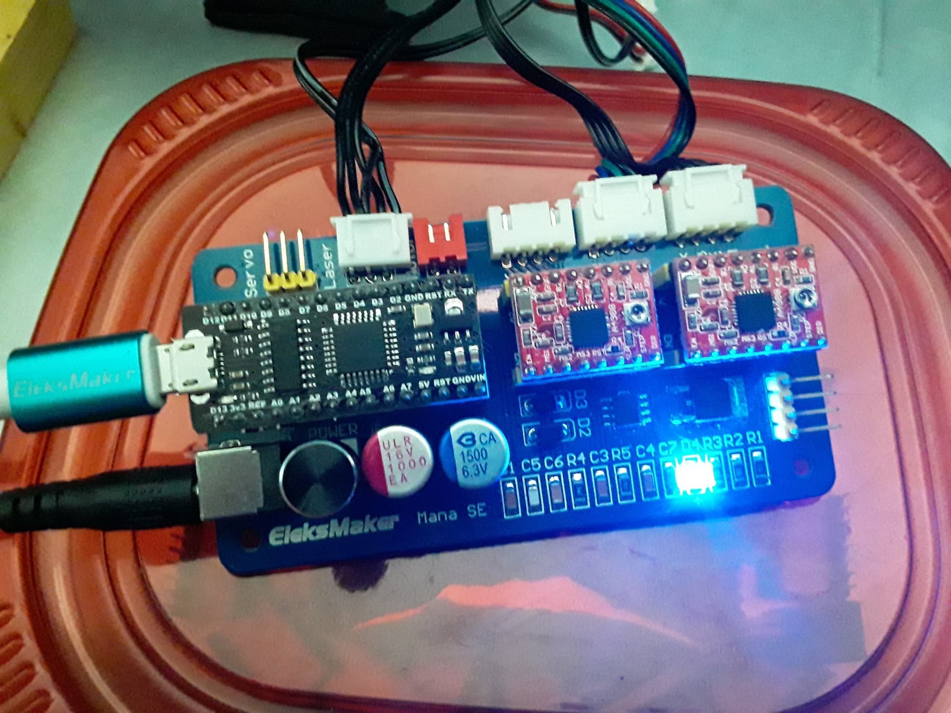
My initial bench testing has some notes in the main Jackpot board development thread.

I started playing with the board using a 24V wall wart switching power supply, but since the JL1 comes with a 12V power supply and I believe has a 12V laser, I’ll find a suitable test power supply as I’m not quite ready to cut up the stock JL1 power supply cable.

If I make any notable progress on the cheapo enclosure I’ll post that in this tread as well.

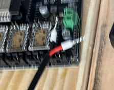
Sorry for the fuzzy picture of the wall wart and ferrules- I didn’t notice the iPhone was having a rare cant focus moment.
image

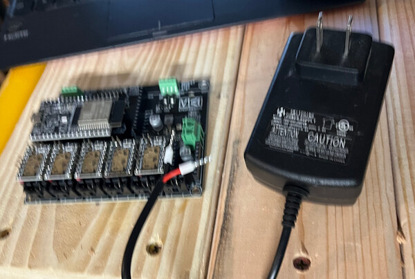
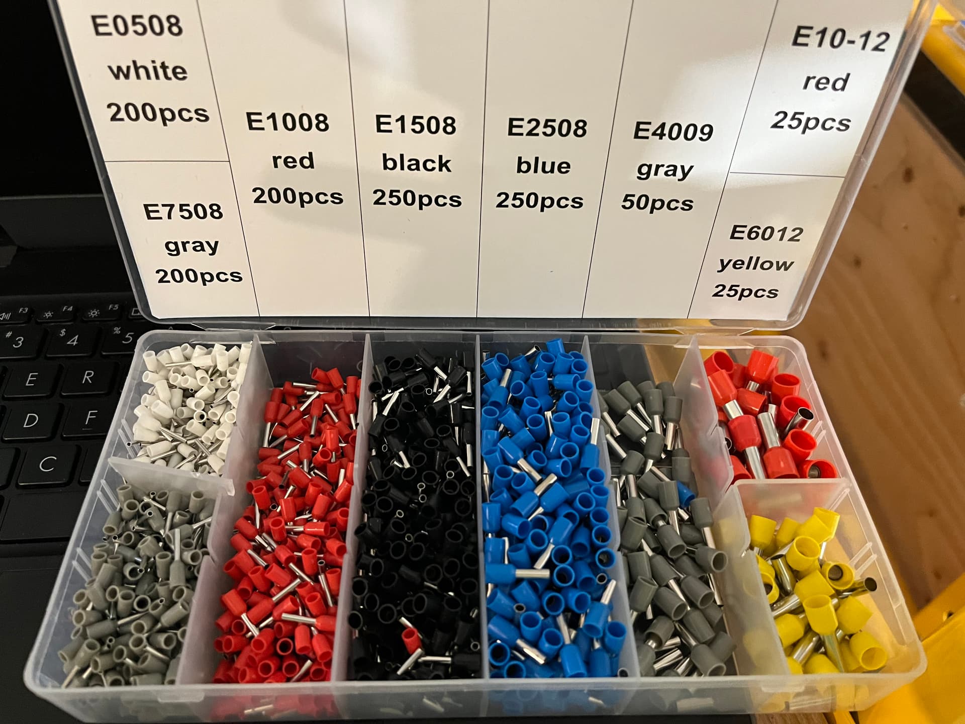
I always put crimp ferrules on wire leads when installing into screw clamps. The wires can’t birdcage and get lose, though that tiny wire AWG is probably not likely to ever have that problem on a Jackpot.

4 Likes

Following. As i too have same jl1!

4 Likes

Dual Y drive, single X, any Z?

I think this will be easy if you take a look at both my LR and MPCNC yaml files you will see how to change a stepper location, but you can really just use the LR yaml and make a couple pin changes.

1 Like

No Z. I might eventually add one of @dkj4linux manual adjustable Z, but unlikely to have a stepper driven Z any time soon if ever.

Good input, thank you. I was just sitting down to start looking for a source yaml file and to figure out some kind of mapping plan for the wiring as I convert it.

Can I just pull the extra 2 steppers or do I need to delete or change parts of the yaml to tell FluidNC not to drive them?

2 Likes

Either way. I would just leave it, and not install any drivers. That way if someone wants the code to add a powered Z they can just install a driver and be ready.

pio26-27 should be ready for your ttf/pwm. I would think activating the laser part I commented out and commenting out the line you choose to you and I think you are ready to go. Unless you need another pin for air or something.

From there you can make a input an emergency stop button or an interlock.

1 Like

More notes:

I took a cut at mapping the connectors on the JL1 controller. See below.
NOTE: Y steppers are wired in parallel!


I wonder if these were already mapped out by @dkj4linux - I’ll explore his threads later.

Here’s a close up of the parallel wiring on the Y steppers. The connector for the X axis limit switch is the connector above the stepper. The right hand side has the harness going into the cable chain and on to the controller. The parallel stepper wiring that goes to the left runs through the 2040 extrusion (bit down the cable chain) across the X axis and when it emerges plugs into the Y stepper on the far side:

I also grabbed the GRBL settings. (I am not a GRBL expert; Posting here so we can refer to them as I adapt to the Jackpot board. I’ll try and translate these at some point and add comments)

$1=255       Step idle delay, milliseconds
$2=0         Step port invert, mask
$3=2         Direction port invert, mask
$4=1         Step enable invert, boolean
$5=1         Limit pins invert, boolean
$6=0         Probe pin invert, boolean
$10=1        Status report, mask
$11=0.010    Junction deviation, mm
$12=0.002    Arc tolerance, mm
$13=0        Report inches, boolean
$20=1        Soft limits, boolean
$21=1        Hard limits, boolean
$22=1        Homing cycle, boolean
$23=2        Homing dir invert, mask
$24=200.000  Homing feed, mm/min
$25=5000.000 Homing seek, mm/min
$26=250      Homing debounce, milliseconds
$27=1.500    Homing pull-off, mm
$30=1000     Max spindle speed, RPM
$31=0        Min spindle speed, RPM
$32=1        Laser mode, boolean
$100=80.000  X steps/mm
$101=80.000  Y steps/mm
$102=80.000  Z steps/mm
$110=5000.000 X Max rate, mm/min
$111=5000.000 Y Max rate, mm/min
$112=5000.000 Z Max rate, mm/min
$120=1000.000 X Acceleration, mm/sec^2
$121=1000.000 Y Acceleration, mm/sec^2
$122=1000.000 Z Acceleration, mm/sec^2
$130=220.000  X Max travel, mm
$131=290.000  Y Max travel, mm
$132=1.000    Z Max travel, mm


It’s a little weird to me that the laser module wiring and the endstop wiring are all on a single connector. This is unlikely to be an easy swap.
I’m most likely to split these out and make my own harness terminations when I map the various pins to the laser module.

I’m also debating whether to keep the parallel y stepper wiring.
Note also that there’s only a single limit switch for Y. If I don’t keep the parallel wiring for the Y steppers, then I wonder if it’s worth installing a 2nd limit switch for the 2nd Y.
That should make it easier to square up the machine, right?

I still need to work on getting the latest UI on my Jackpot board. I was able to flash it to 3.7.6 using the web based flasher. FluidNC Web Installer
That looks to have something besides the V1e GUI at first glance.

I was unable to use the .bat file in the V1e distribution as when I tried to run the .bat file it launched an x64 .exe. That old laptop has a 64 bit processor but as it only has 2Gb of RAM is running 32 bit windows. So, all I get from the .exe called by the .bat file is an error message noting it isn’t on the correct windows system.

I’m not sure how useful the crosshair laser pointer is to everyone, but on the stock (Pre-GRBL) firmware, the crosshair pointer turned on when powered up and turned off when the laser module was energized. Post GRBL flash, the crosshair laser does nothing.

I’m debating making it live again if there’s a way to map it to a button or some other FluidNC way of controlling it in an at least semi-standard way.

EDIT: Put annotations on the GRBL setting to help interpret them.

1 Like

image

Hey @MakerJim, curious what’s the AWG equivalent of the ferrules you used for powering the board? Trying to figure out if the same ferrules would fit a 16AWG 10A connector.

1 Like

@azab2c - Those were the smallest available ferrule I had in this no-name Chinese kit that I have. The white ones in the upper left:

Those wires in the stock power supply wiring are small. Smaller than 16AWG. Probably more like 20 or 22. Small.

Should be the same? After you flashed it you logged in over wifi and it looked different? Screenshot?

with a running jackpot you can actually do all the updating from the Webui itself. The bin and the .gz file I can take some screenshots tomorrow, both should be in the WIFI folder. you do an OTA update for the bin reboot and just upload the new html.gz file. reboot.

Yeah there area few open button to use.

For the rest I would just wire it as is and make it work. Changing any wiring is much easier after you have proven it out as is. Not much point in dual an such a small machine.

1 Like

Noting a detail from @dkj4linux original thread about the JL1 Here:

He was able to use a cheapo controller and there is detail on how he connected the laser module shown in this picture from that thread. (He didn’t use limit switches nor the crosshair pointer. )
This is great detail and I’m appreciative of his taking the time to document it.

Using the orientation of that connector on the “Laser” header on the board, I’ll have an easier time mapping things out. Still mining his thread for additional details. Good stuff!

Editing to add the wiring guide for the Mana SE board shown above. This will help me (and maybe others) when interpreting the wiring shown above.
Looks like the far left is +12V (motor/board inlet power), then GND, and then PWM. This makes sense as the 4th position in the JL1 connector goes to a limit switch, and that limit switch uses the GND as well, which is why the JL1 harness has two wires in the 2nd position from left on the “LASER” connector.

2 Likes

When I ran the web flasher the first time, after logging back in I had just a file upload menu instead of the GUI.
Just tried again, and this time I appear to have a working GUI and I’m still on 3.7.6. No idea what I screwed up along the way. I’ll wait for those screenshots tomorrow.

At least it looks like it’s robust and at least fairly “Jimmy proof” Speaking as a Jimmy myself, of course :wink:

Good suggestion.
I will need to break out the limit switch that is shared with the laser module connector as I do want to use limit switches on my JL1. They really aren’t technically necessary- but I like repeatability. The limit switch connectors are the wrong size to just drop on the Jackpot headers.
By the way, what is the correct mating connector for the limit switch IO headers on the Jackpot?

Jim,

I have re-engaged with my rebuild of the JL1 as well, but when I tried to run it today the laser “spot” was all blurry. Occasionally it would snap back to a point, but I have no ides what’s going on. Rather than try and replace the laser module I guess I’ll just build a bigger version to put in the Ortur enclosure.

Mike

Mike- Let me know if I can help in any way. That’s a really weird sounding laser module problem. Is the lens loose?

Below is the mounting hole pattern on the JL1 frame for the stock controller box. I forgot to take measurements when I had it apart for pictures so I’ll grab those next time.
@vicious1 are there any stock mounts for the Jackpot that I can remix. It should be fairly simple to put 3 holes into a box that is otherwise suitable for the Jackpot.

The three circled holes are how the stock controller box is mounted.

The flat head screws go to standoffs that mount the y axis limit switch on a little PCB.

Edit to add: Of course, there’s a beautiful design to put the Jackpot on an LR3 on Printables, but unfortunately that isn’t quite right to slap here. I’ll think about it some more.
https://www.printables.com/model/561771-jackpot-cnc-controller-minimal-lr3-case/files

It didn’t appear loose, I did remove it to check for debris and found something that seems to be between the diode and the lens.

That silver bit in the lower right doesn’t appear to be loose, but I can’t believe it should be there.

Mike

Holy cow! That looks like the laser diode itself is loose within the assembly. Can not be good!
But, if it was that, I can’t imagine how it would still be getting powered, unless they bonded the laser diode into the lens housing with flying leads or something.
No way that’s right.

Jime,

I noticed that the wire lengths were “just enough” for the lengths as installed.

I bought this 6-conductor wire and intend to have a little more slack.

Mike

Jim,

I also made a set of leg risers so I could place a larger object below the whole frame:

JL1 Leg extensions

They add 50mm to the height of the legs. I used one of @dkj4linux manual z-axis adjusters so I can lower the laser to the correct height, even with the leg extenders on.

Mike

2 Likes

The laser module on the Cenoz machine was terrible… never focused to a nice spot and had sorry power. I had several other laser modules on hand… common 3-pin versions for +12V, GND, and PWM. If you use the included laser module’s wiring to identify those 3 wires – and the black wires they hook to – you can then mark the black wires and and install a new laser module on there. That what I did here…

My Z-axis adjuster was good enough… but not my leg extentions? :stuck_out_tongue_winking_eye:

1 Like