I didn’t have Chunky Soups in the pantry. ![]()
MB
They are just standard 2.54mm headers.
If you follow the link from the docs page I have included the cad for my LR3 box but that is the only one I know of at this time. My top priority is get the LR3 and MPCNC squared away before trying anything custom.
I too bought one of these and I’m watching your progress with interest. I don’t have another raspberry pi to run it, so I’ve been thinking about putting it on the mpcnc or the 3d printer, but a jackpot might be the answer here.
It has been reprogrammed to GRBL, and has a rotary and some blanks for leather patches and some pens… one of these days.
Doing some work on the config.yaml.
The original JL1 controller GRBL setup seems to be 80 steps/mm.
What’s the microstepping setup on the Jackpot?
The example config.yaml has 800 steps/mm, so I’m sure I’ll need to change this.
Moving on to the laser section, Ryan noted:
So, I think that means that my config for laser should look like this:
Laser:
pwm_hz: 5000
output_pin: gpio.26
enable_pin: gpio.27
disable_with_s0: false
s0_with_disable: true
tool_num: 100
speed_map: 0=0.000% 255=100.000%
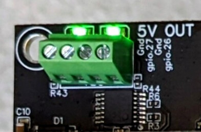
Those are found on the screw terminals in the 5V out section of the Jackpot:
I’m going to do a stupid simple flat adapter plate to mount the jackpot for now.
The hole spacing I came up with on the JL1 for the existing controller box is 35.5mm horizontally for the upper mounting holes and 72mm between the upper two and the lower one.
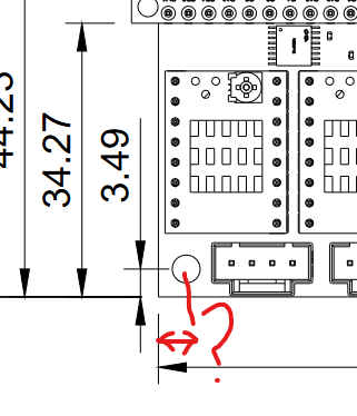
I’ll need to measure the Jackpot as I get 73mm between mouting holes vertically and 93mm horizontally on the 3.55mm diameter mounting holes. The horizontal spacing isn’t explicitly called out but I bet it is the same 3.49mm up as well as over as shown in this bit from the documentation:
I’ll sketch a mounting plate up and get it on one of the printers, then will work on transferring some of the harness over. Perhaps another update later.
You are going to need to open up the yaml file to make all the adjustments. You will see them there 100.
All are 3.5mm from both sides. I am not sure why the dims are all off by ~0.01 annoying but I am sure I did something funky in EasyEDA
Working on the JL1 again this morning.
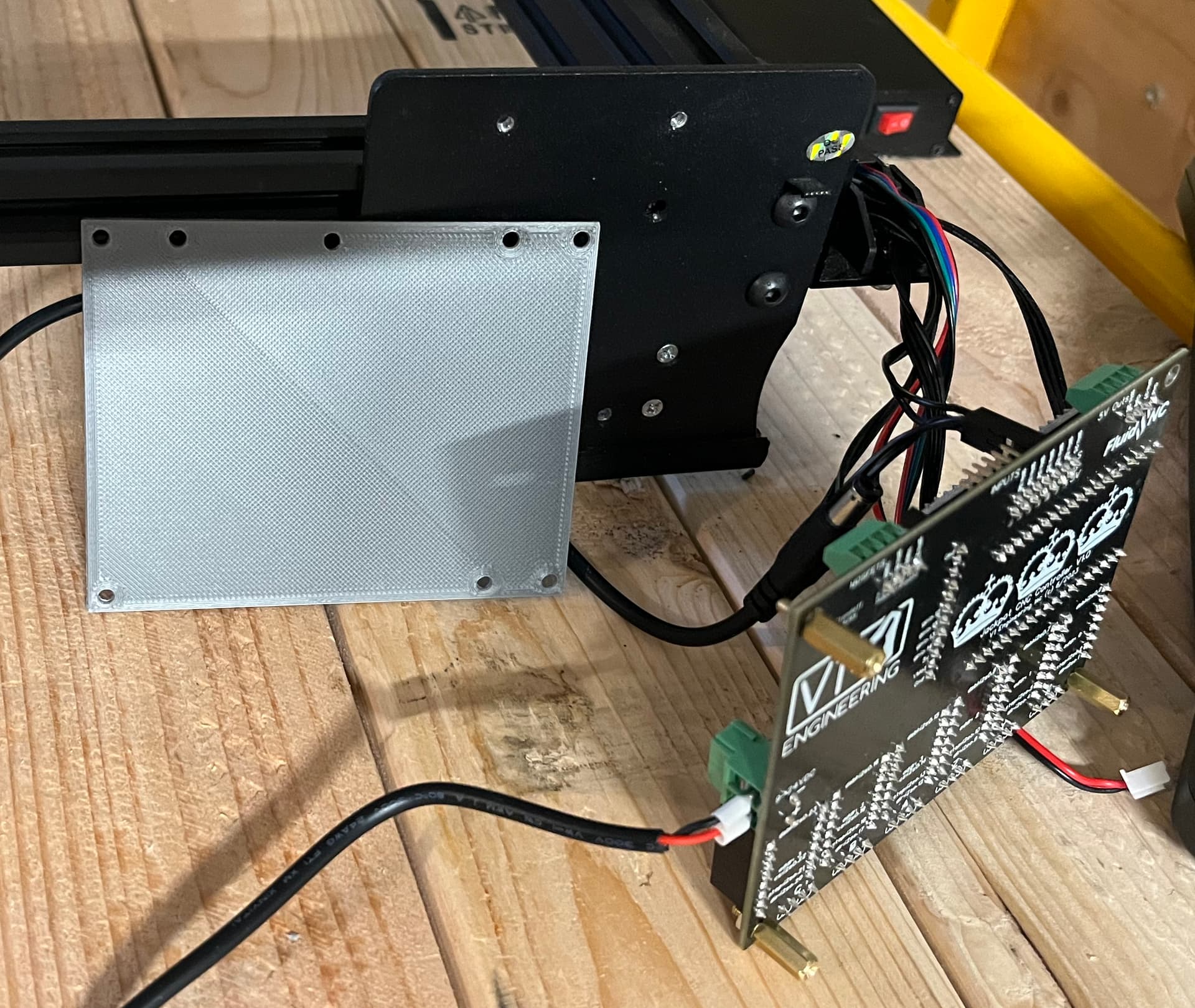
My quick mounting plate printed last night, and I messed up one screw hole location. Nothing I couldn’t fix quickly with a 1/8" drill bit. I realized I didn’t have any M3 standoffs around, so I grabbed some from a kit of Raspberry Pi hardware (M2.5 standoffs). Below you can see the plate on the JL1 frame. I’ll revise this a bit when I get a better case design together. Notable are that the wire runs from the JL1 are very tight and there’s not a bunch of slack, particularly with the endstops.
After that image was taken, I mounted the Jackpot on the plate, and swapped from my test 24V wall wart to using the JL1’s 12V 5A supply. I connectorized the JL1 with a pair of Anderson PowerPole connectors because I will re-use it. For a permanent setup I’m probably going to mount one of my old metal frame power supplies left over from the old Lulzbot series printers that I still have around.
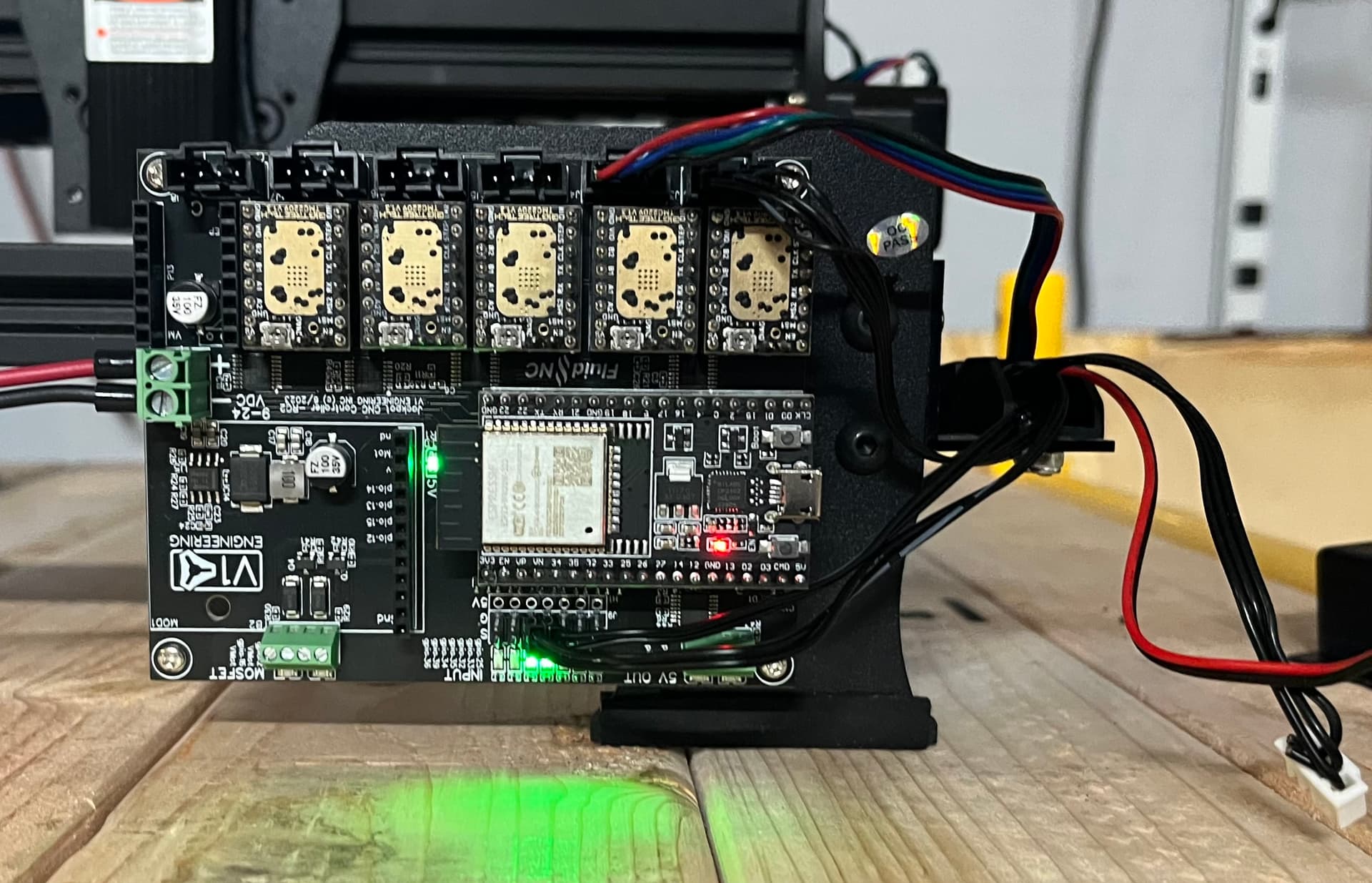
That will go on the enclosure I’m working on. At any rate, here’s the setup with things attached again:
One notable thing that seems a bit of a bummer is that the connectors on the jackpot for MOSFET and 5V out have the wiring going out such that the wires/ferrules will require additional case room to accommodate the wire bend radius. It will also be a mild annoyance to install/remove that wiring when in a case.
This seems it would be cleaner if the IO emerged straight up instead of to the side, but it’s nothing I can’t work around when I make a better case for the Jackpot on the JL1.
Also notable is that the endstop LEDs lit up when plugged in. I suspect that means whatever config is in the default config is wrong- which is fine because I’m about to put a test config.yaml on for the JL1.
I tried jogging the axis from the web UI, but got no motion in X or Y. Probably a config issue so I’ll be working on that.
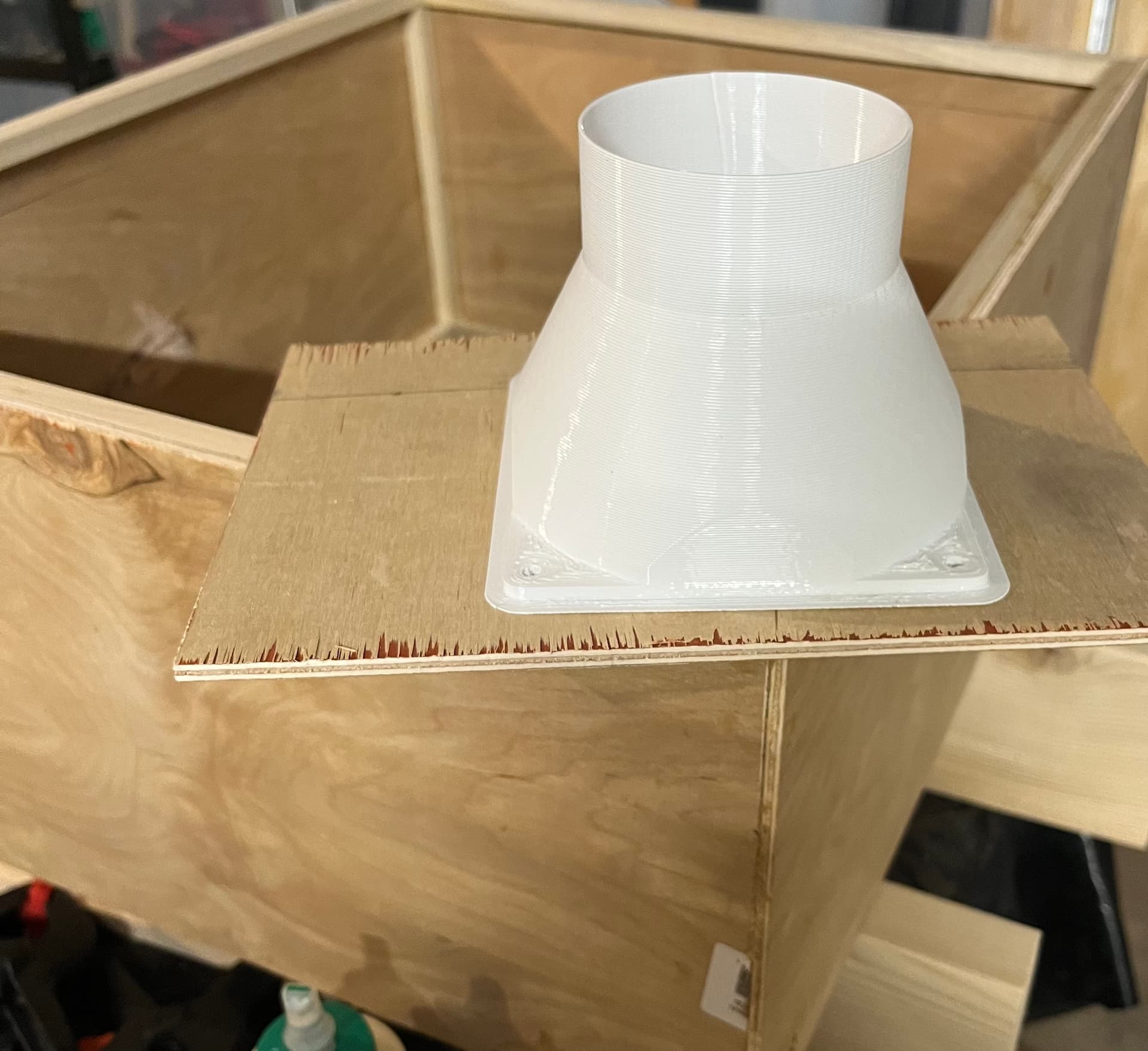
I also glued up my scrap parts enclosure a bit. This is entirely made from scrap- I had some 1/8" plywood and some 1/2" square dowels laying around from a different project. I plan to add a top that has some 1/8" orange acrylic and mount a simple exhaust using a 12V 120mm PC case fan (also junk bin scrap from an old PC). Total material cost so far for the enclosure is $10 for the acrylic and probably $2 worth of recycled PET. The 3" hose adapter was printed on the TAZ5 with a 1mm nozzle and .667 layer height. Primarily because it printed in about an hour instead of FOREVER as it would with more reasonable nozzle and layer height. The STL for the vent adapter is linked below.
Here’s the fan to vent hose adapter:
https://www.printables.com/model/24023-120mm-fan-to-3in-duct-reducer
I’m going to play a bit with trying to put my candidate config.yaml on the Jackpot, then will probably spend some time sorting through the motion stuff. Still to go is figuring out the laser module pins and setup. With some luck, maybe it’ll be alive enough to test laser module operation before the day or at least weekend is over.
Open is lit dark, triggered/closed is lit up. You set what a trigger does in the firmware, but the LED’s always indicate the same thing. Open or closed circuit.
If you have fluidterm running while you are trying to do anything even restarting it will show any errors. that can help us with your config very quickly, or link your yaml file. If you start with either of my configs and the endstops are CLOSED lit up. the axis should move. From there you can adjust if your endstops are NO/NC, and your steps/mm.
If you made your own config, it probably requires homing all axis before any motion. I took that out of ours.
Thanks, noted. I’ll get fluidterm running as I work so I can share whatever I see.
I took your sample laser yaml and made just a few minor modifications, but haven’t yet uploaded it.
I’m on my way to do that so hopefully that gets things fired up.
I would just start with the LR yaml. Make sure everything moves and get the endstops working right. Then turn off my pin26/27 edits and add the laser stuff. Motion and endstops first. Then laser.
Is that the same as the config.yaml under LowRider CNC on github here:
To use fluidterm.py I’ll need to have the USB connected when using the system. I’ll get that running shortly.
I’m going to go put your LowRider config.yaml on the Jackpot and see how that works for me.
Making some good progress.
With the v1e LowRider config.yaml loaded on the Jackpot, I’m now able to jog X and Y axis around.
Some details and observations as I have started working with it.
Endstops still aren’t working. I discovered the @limits function, and the X/Y/Z endstop states are inverted (always triggered except when I hit the switch)
Homing Y seems to move away from 0 instead of towards.
Trying to home X, it also ran away to the 0 direction (Left as seen in my pictures above, away from the limit switch which is on the right side). It eventually hit and then drove for a long time and stopped.
Note: there’s no obvious way to kill a move from the UI. I’ll add a stop switch at some point.
I also noticed that the X motor is running moderately warm, while the parallel Y motors are very cool.
I reduced the drive current and holding current for the X motor to half the default values.
I realized that I have not yet installed an SD card. Duh! Found that from looking at fluidterm outputs as shown below. I also see that it’s not happy about the missing 6th driver (axis C)
jim@BR1100CKA:~$ python3 fluidterm.py
--- Fluidterm on /dev/ttyUSB0  115200,8,N,1 ---
--- Quit: Ctrl+] or Ctrl+Q | Menu: Ctrl+T | Help: Ctrl+T followed by 'H' ---
E (2098785) sdmmc_io: sdmmc_io_reset: unexpected return: 0x102
[MSG:ERR: sdmmc_card_init failed code 0x0x102]

[MSG:ERR: C Axis TMC driver not detected - expected 0x0x21 got 0x0x0]
I ran into an interesting error sequence uploading the config.yaml changes.
I used the file upload function, uploaded config.yaml, and then reloaded fluidnc with the power button on the GUI. Did that two or three times with no issues. Then, the next time I tried an upload I got this in the fluidterm:
E (50727) sdmmc_sd: sdmmc_init_sd_if_cond: send_if_cond (1) returned 0x108
[MSG:ERR: sdmmc_card_init failed code 0x0x108]
[MSG:WARN: Low memory: 14836 bytes]
[MSG:WARN: Low memory: 13816 bytes]
[MSG:WARN: Low memory: 13696 bytes]
[MSG:WARN: Low memory: 13428 bytes]
[MSG:WARN: Low memory: 12684 bytes]
[MSG:WARN: Low memory: 12532 bytes]
[MSG:WARN: Low memory: 12404 bytes]
[MSG:WARN: Low memory: 12276 bytes]
[MSG:WARN: Low memory: 12148 bytes]
[MSG:WARN: Low memory: 12096 bytes]
[MSG:WARN: Low memory: 11968 bytes]
[MSG:WARN: Low memory: 11848 bytes]
[MSG:WARN: Low memory: 11720 bytes]
[MSG:WARN: Low memory: 11600 bytes]
[MSG:WARN: Low memory: 11440 bytes]
[MSG:WARN: Low memory: 10020 bytes]
[MSG:WARN: Low memory: 8428 bytes]
[MSG:WARN: Low memory: 6852 bytes]
[MSG:WARN: Low memory: 5268 bytes]
[MSG:WARN: Low memory: 3684 bytes]
[MSG:WARN: Low memory: 3676 bytes]
[MSG:WARN: Low memory: 3548 bytes]
[MSG:WARN: Low memory: 3516 bytes]
[MSG:WARN: Low memory: 2724 bytes]
[MSG:WARN: Low memory: 2600 bytes]
[MSG:WARN: Low memory: 2576 bytes]
[MSG:WARN: Low memory: 2452 bytes]
[MSG:WARN: Low memory: 2396 bytes]
[MSG:WARN: Low memory: 2272 bytes]
Following that, I lost connection to the Jackpot ESP32. I ended up pulling the USB and killing power to the Jackpot board. After that, when trying to connect to it, I was getting an error that the ESP32 was not accepting the default 12345678 password.
After a couple more power cycles, I went off to do some work on my enclosure, and when I came back I was able to connect. Weird.
What’s the correct workflow for uploading a config.yaml and then restarting or applying it?
Questions:
How do I tell FluidNC the correct state of the enstop? I"ve toggled the config directive back and forth between these, with no joy:
    motor0:
      limit_neg_pin: gpio.25:high
also:
    motor0:
      limit_neg_pin: gpio.25:low
To try and get the direction correct, I fiddled with these:
 homing:
      cycle: 3
      positive_direction: false
      mpos_mm: 0
Changing positive_direction to true didn’t flip the axis movement as I’d expected… so a head scratcher for me.
They work fine just backwards, that is to be expected change the yaml for each endstop. from high to low.
That means you need to reverse the steppers or change from a minimum endstop to maximum. I don;t have the machine so I have to just guess.
You can add a macro and or a button.
That is not an error just telling you what it sees. Put in a card, does it work…it should. There is no sixth driver so it is telling you that.
Power down wait a minute and reboot. Sounds like you might have interuptted an upload. Or if you are doing a lot of work use the fluid term. I would not do all that editing and testing on wifi, you need to see the errors.
Did you save, power down, and reboot to load changes?
I now have everything connected and working on the JL1 -except- the laser. ![]()
Below I’ll quote the working config.yaml.
Maybe… but I didn’t really make progress until I grokked that the LowRider config has multiple Y motors each with their own driver, and the JL1 has a single driver and two steppers in parallel. I ripped out the extra config and things started making more sense when being reported with $limits. It has something to do with the LowRider config having endstops defined in the other motor driver.
What I had to do here was rip out the extra motor configs, then set the config as shown in the config.yaml below.
Earlier, when I was jogging the X and Y, the axis moved in the correct direction, so I knew the connector at the jumper didn’t need to be flipped.
Regarding the out of memory errors and reboots, I am able to reproduce that semi regularly.
Steps:
Below is the config.yaml as I have it, and everything I have tested is working fine. Now I will try to sort out the laser.
board: Jackpot TMC2209
name: JL1_Laser
meta: 08-27-2023 MakerJim

planner_blocks: 32

stepping:
  engine: I2S_STATIC
  idle_ms: 255
  pulse_us: 4
  dir_delay_us: 1
  disable_delay_us: 0

uart1:
  txd_pin: gpio.0
  rxd_pin: gpio.4
  rts_pin: NO_PIN
  baud: 115200
  mode: 8N1

axes:
  shared_stepper_disable_pin: NO_PIN

  x:
    steps_per_mm: 40.000
    max_rate_mm_per_min: 9000.000
    acceleration_mm_per_sec2: 200.000
    max_travel_mm: 220
    soft_limits: false
    homing:
      cycle: 3
      positive_direction: true
      mpos_mm: 220
      feed_mm_per_min: 300.000
      seek_mm_per_min: 1500.000
      settle_ms: 500
      seek_scaler: 1.100
      feed_scaler: 1.100
    #X
    motor0:
      limit_neg_pin: NO_PIN
      limit_pos_pin: gpio.25:high
      limit_all_pin: NO_PIN
      hard_limits: false
      pulloff_mm: 4.000
      tmc_2209:
        uart_num: 1
        addr: 0
        cs_pin: NO_PIN
        r_sense_ohms: 0.110
        run_amps: 0.300
        hold_amps: 0.200
        microsteps: 8
        stallguard: 0
        stallguard_debug: false
        toff_disable: 0
        toff_stealthchop: 5
        toff_coolstep: 3
        run_mode: StealthChop
        homing_mode: StealthChop
        use_enable: false
        direction_pin: I2SO.1
        step_pin: I2SO.2
        disable_pin: I2SO.0

  y:
    steps_per_mm: 40.000
    max_rate_mm_per_min: 9000.000
    acceleration_mm_per_sec2: 200.000
    max_travel_mm: 280
    soft_limits: false
    homing:
      cycle: 3
      positive_direction: false
      mpos_mm: 0
      feed_mm_per_min: 300.000
      seek_mm_per_min: 1500.000
      settle_ms: 500
      seek_scaler: 1.100
      feed_scaler: 1.100
    #Y
    motor0:
      limit_neg_pin: gpio.33:high
      limit_pos_pin: NO_PIN
      limit_all_pin: NO_PIN
      hard_limits: false
      pulloff_mm: 4.000
      tmc_2209:
        uart_num: 1
        addr: 1
        cs_pin: NO_PIN
        r_sense_ohms: 0.110
        run_amps: 0.600
        hold_amps: 0.400
        microsteps: 8
        stallguard: 0
        stallguard_debug: false
        toff_disable: 0
        toff_stealthchop: 5
        toff_coolstep: 3
        run_mode: StealthChop
        homing_mode: StealthChop
        use_enable: false
        step_pin: I2SO.5
        direction_pin: I2SO.4
        disable_pin: I2SO.7

i2so:
  bck_pin: gpio.22
  data_pin: gpio.21
  ws_pin: gpio.17

spi:
  miso_pin: gpio.19
  mosi_pin: gpio.23
  sck_pin: gpio.18

sdcard:
  cs_pin: gpio.5
  card_detect_pin: NO_PIN
  frequency_hz: 20000000

#probe:
#  pin: gpio.36:low
#  toolsetter_pin: NO_PIN
#  check_mode_start: true

start:
  must_home: false

#coolant:
#  flood_pin: gpio.2
#  mist_pin: gpio.16
#  delay_ms: 0

control:
  safety_door_pin: NO_PIN
  reset_pin: NO_PIN
  feed_hold_pin: NO_PIN
  cycle_start_pin: NO_PIN
  macro0_pin: NO_PIN
  macro1_pin: NO_PIN
  macro2_pin: NO_PIN
  macro3_pin: NO_PIN

macros:
  startup_line0:
  startup_line1:
  macro0:
  macro1:
  macro2:
  macro3:

user_outputs:
  analog0_pin: NO_PIN
  analog1_pin: NO_PIN
  analog2_pin: NO_PIN
  analog3_pin: NO_PIN
  analog0_hz: 5000
  analog1_hz: 5000
  analog2_hz: 5000
  analog3_hz: 5000
  digital0_pin: gpio.26
  digital1_pin: NO_PIN
  digital2_pin: NO_PIN
  digital3_pin: NO_PIN

Laser:
  pwm_hz: 5000
  output_pin: gpio.27
  enable_pin: gpio.2
  disable_with_s0: false
  s0_with_disable: true
  tool_num: 0
  speed_map: 0=0.000% 1000=100.000%
  off_on_alarm: true

# pwm:
#  pwm_hz: 5000
#  direction_pin: gpio.26
#  output_pin: gpio.27
#  enable_pin: NO_PIN
#  disable_with_s0: false
#  s0_with_disable: true
#  spinup_ms: 0
#  spindown_ms: 0
#  tool_num: 0
#  speed_map: 0=0.000% 1000=100.000%
#  off_on_alarm: false

# 5V out gpio.26/27
# VMot out gpoi.2/16
# In's left to right gpoi.25/33/32/35/34/39/36
EDIT: Updated the config.yaml above to the one that I got working down below.
Your pwm is commented out. Need that or the laser does not know how much power you want to use!
Absoltuely, using my LR cofig just gets you started. With all the rest of the config stuff.
I think for now you should only be using one at a time. If you are plugged in with usb I would do all file transfer through fluid term (ctrl+U). In daily use you will be connected with wifi or lightburn only, following the rest of my laser instructions. The memory issues should not come into play. You might upload one file per use without a reboot. On top of that when your config is right you will not be fighting errors as well.
I Am glad you are trying an out of the intentions install and I am sorry I do not have a ton of time to help but I am scrambling to ship orders and keep up with all the other jackpot stuff behind the scenes. You have on of the first 15 boards out there…didn’t expect anything other than the CNC’s at this point. If you do not get there by next weekend I should have some more time to help with this use case. I just need to get the LR and MPCNC dialed in first.
You’ve already helped me get much farther than I had hoped.
I’m expecting the product launch to really go well for you and hope that the issues I’m running into will help understand what others might run into.
Thank you for your awesome support, as always!
Yes, that was deliberate on my part as I wanted to get everything else working reasonably well before I even tried to hook up the laser. Now that I’m at that point, I’ll go ahead and work on the laser module interface.
I’m about to wire up an pigtail that should land as flying leads on the jackpot connectors, and then I’ll connectorize it to mate up with the original JL1 harness.
Hopefully I’ll have the laser running later this afternoon.
Well… It works.
I had to do some head scratching as it was having panics on startup for a while- but I figured that out.
I had left sections like coolant with the same GPIO that I was using for the laser.
Having those duplicates causes FluidNC to panic.
Once those were removed, it came up happy.
The setup needs some tuning- I need to focus it better, and it behaves a bit different than before.
On the Jackpot the laser seems to have a much higher power level than on the JL1 controller.
That’s probably a good thing. It also seems quiter when moving- and the laser seems to make more noise when running than it did on the JL1 controller. That may relate to my sense that the output is more powerful than on the JL1 controller.
To get this running…
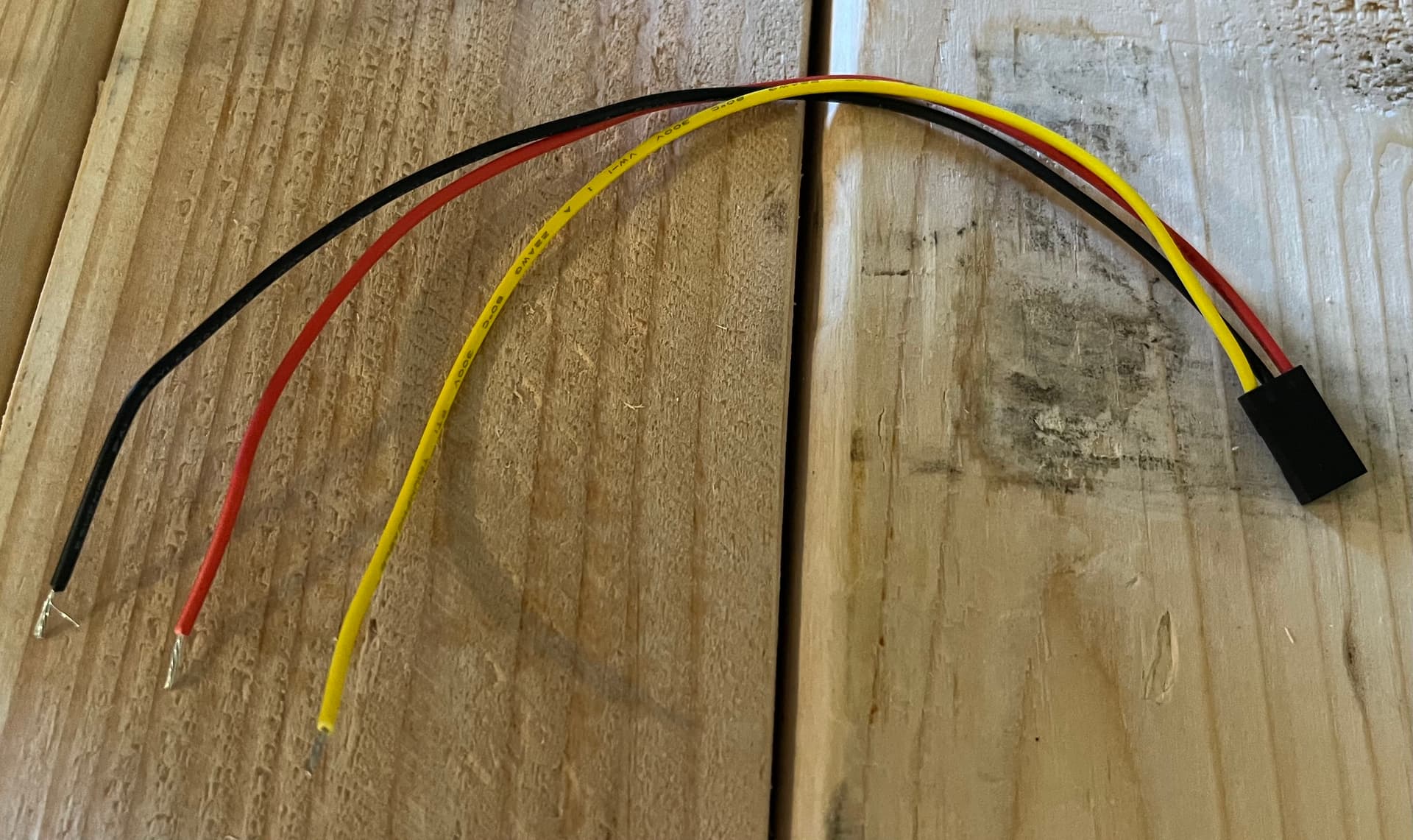
I made a pigtail to install on the Jackpot, then cut off the old connector one wire at a time and landed them in a new connector to mate with the pigtail.
PIgtail:
Pigtail installed, original harness re-connectorized and mated to the pigtail:
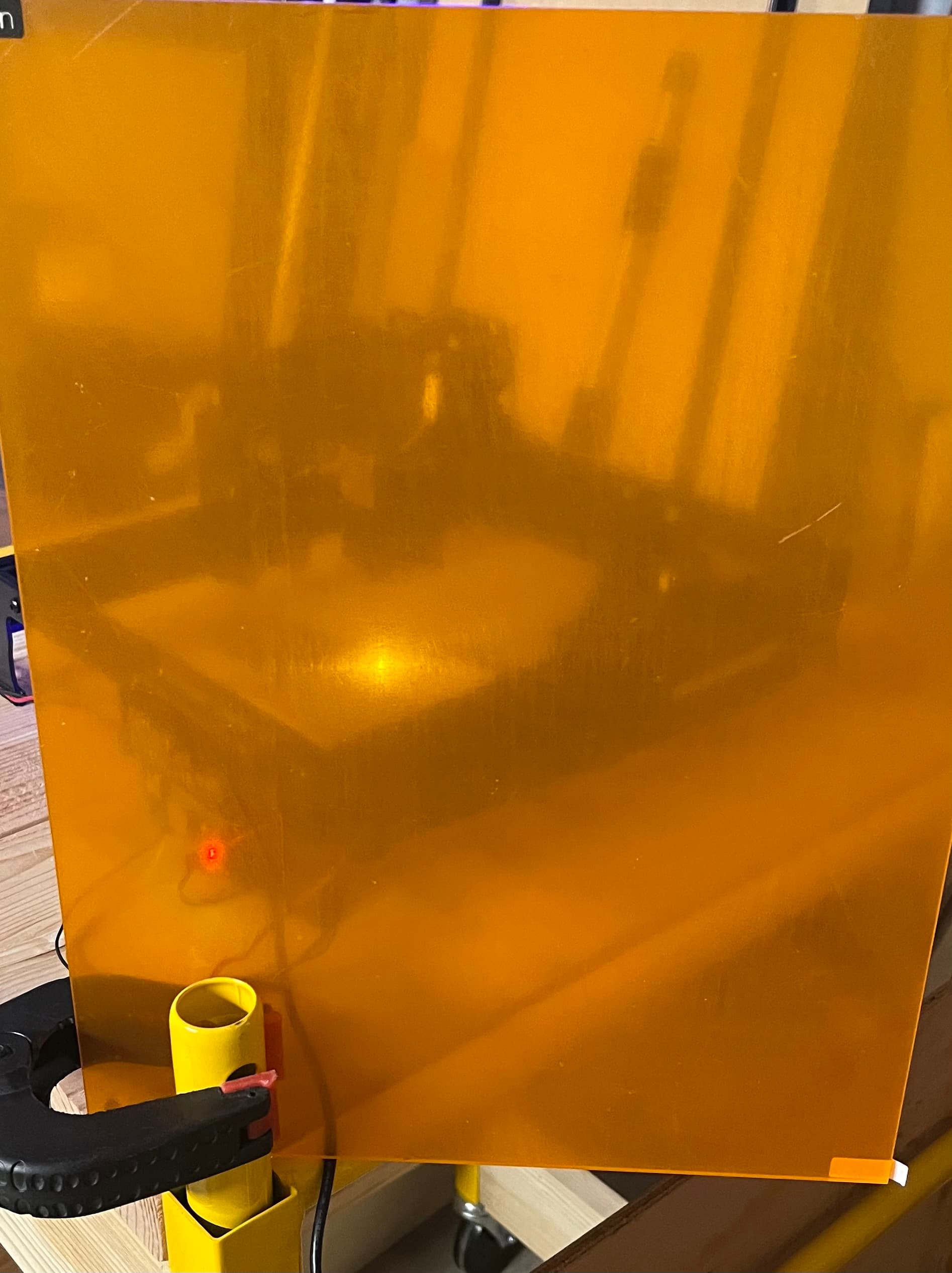
LightBurn material test in progress:
(The orange acrylic I got for the enclosure will work fine in that application!)
Resulting material test.
That crappy pine 1x material is hard to engrave… but it was a cast off piece I didn’t mind sacrificing for a quick test that I thought wouldn’t work. It came out like this on the first try. Not great. Not the worst.
The above was with LightBurn connected. I’m going to try a bit later to take the saved Gcode and run that from the Jackpot as a file from the UI.
I will update the post above with the latest contents of my config.yaml.
Careful powering the laser directly from the jackpot, that port can only handle 2.5A some lasers use more than that. Depending on the laser, you can connect it directly to power and the PWM will turn it on and off (as well as up and down).