I’m creating a thread to document my build, this topic will be linked out from the FluidDial thread shown below.
3 Likes
Starting with Doug’s modified pendant enclosure that fits an RJ-45 keystone jack, I set about to wire up the first of my two M5 Dials and figure out how to load firmware and connect them.
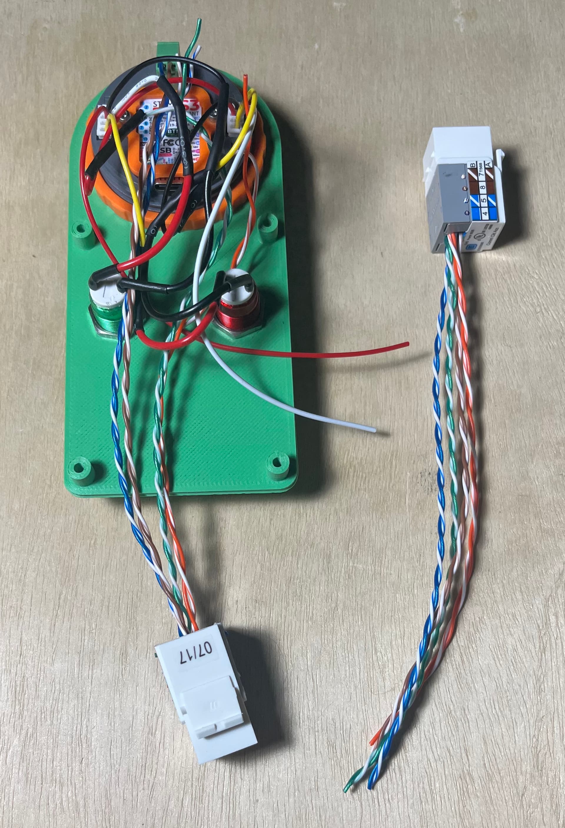
Here’s a pair of RJ45s, wired with short pigtails, 568B standard colors.
I then went and did a git clone of the FluidNC firmware from here:
There wasn’t anything particularly difficult there, I opened the project in VSCode with platformio.
I did discover that as others have previously mentioned, it’s not enough to build and upload the code, you also have to build and upload the filesystem. With that completed, the M5Dial boots and comes up when on USB-C to my ubuntu laptop for the build.
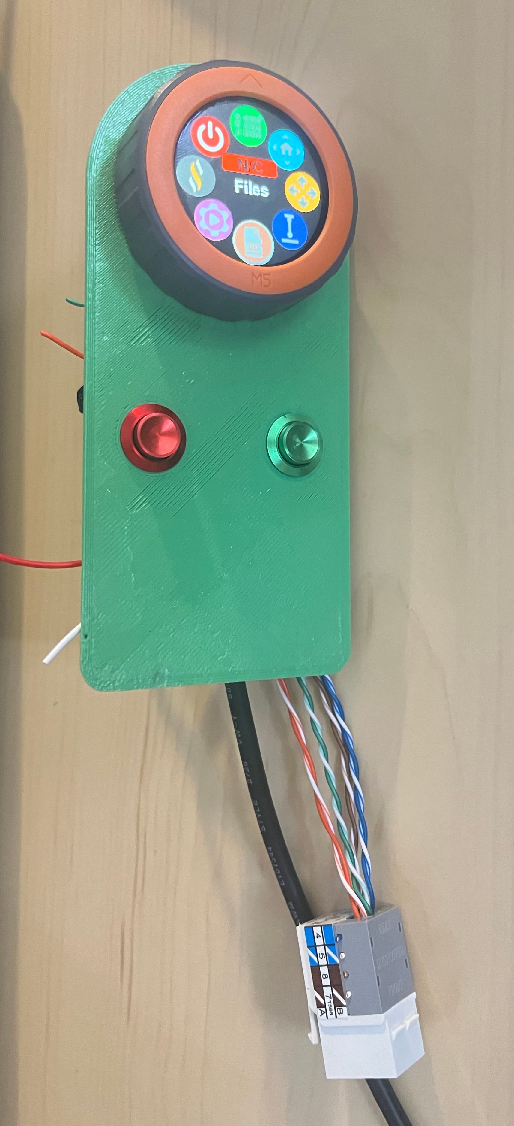
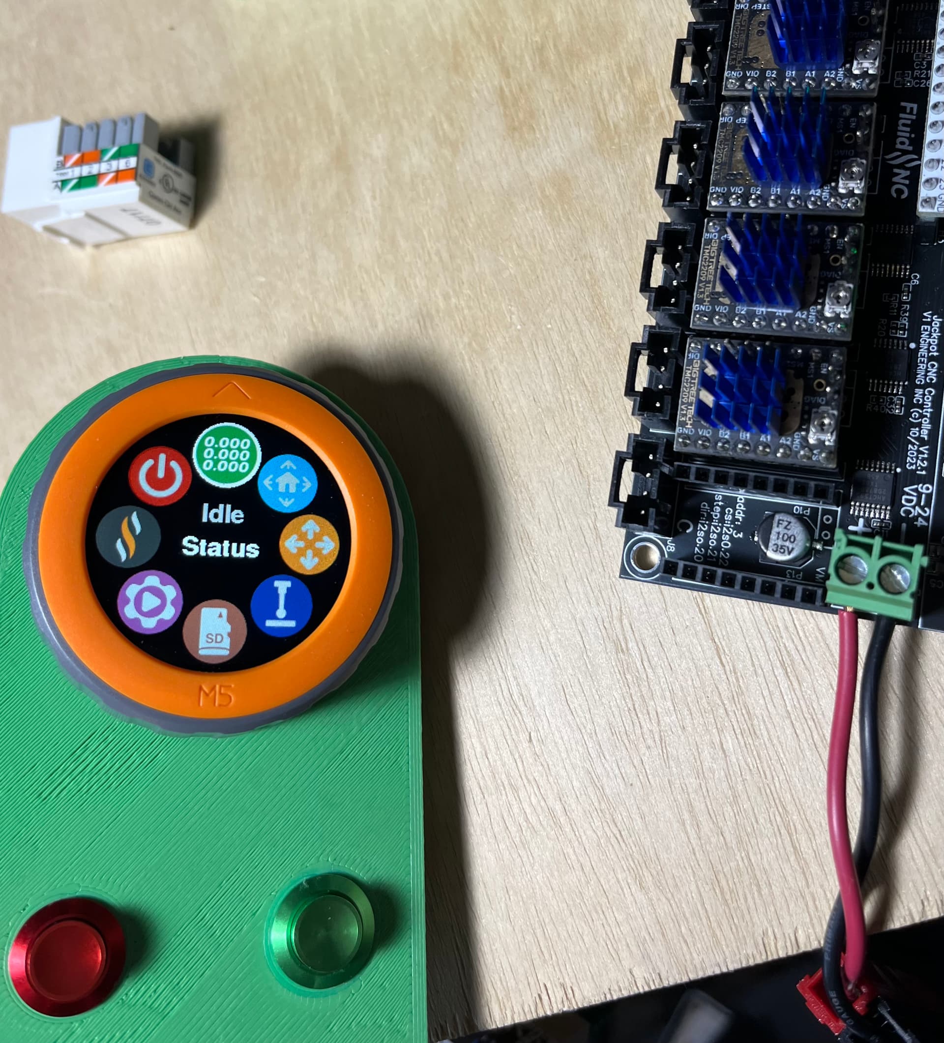
I next built out the pigtail for the Jackpot end, pulled out one of my test Jackpot boards, and loaded that with FluidNC 3.7.16 and the default V1E lowrider config.yaml. I then updated that to add the UART2 section.

As you can see in the image, it only shows NC. I’ve tried flopping the TX/RX pins and the UART speed is correct at 1000000. So, my next steps will be to troubleshoot by building up the 2nd pendant and re-verifying the wiring.

5 Likes

That’s pretty much exactly how I believe I wired it- but I’ll go double check.
For mine, on the RJ45 side, Blue is VMOT, Brown is GND.
UART signals are White/Orange and White/Green.
The buttons (at least, the green button) is working as I can use that button in conjunction with the menu.
On the 2nd one I’m only going to populate those four wires which should be easier to see.
I also had some trimming of the two 4-pin connectors which I’ll note below.
1 Like
In your picture the B side has wires to 1,2,4. It should be 1,3,4.
The A side looks correct.
1 Like
The B side is black/red/white/yellow from the top. Red is not conencted- you can see it goes across the base of the top cover and is the red wire that you can see sticking out to the right.
Black is tied to the black lead of the greeen switch.
White is tied to the red lead of the green switch.
Yellow is tied to the red lead of the red switch.
Red is not connected as noted above.
The green button works on this pendant.
I thought only the UART2 section needed to be added to config.yaml- but now I’m not so sure there aren’t additional config sections.
Will get back to building up the 2nd pendant in a little bit to be able to troubleshoot further.
Thanks for your troubleshooting help- multiple eyes are really useful for odd problem work.
1 Like
Sorry, I didn’t notice the white wire going to the right. I thought the red wire was connected to the button.
This is what I added to my yaml file:
uart2:
  txd_pin: gpio.14
  rxd_pin: gpio.13
  rts_pin: NO_PIN
  cts_pin: NO_PIN
  baud: 1000000
  mode: 8N1

uart_channel2:
  uart_num: 2
  report_interval_ms: 75
2 Likes
You’re very welcome.
Glad it’s working!
1 Like
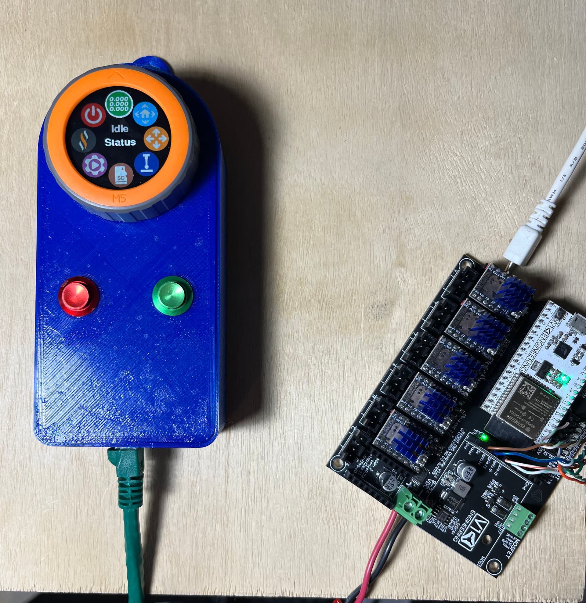
A bit neater on the 2nd pendant. Still messy. But it worked with my test jackpot on the first try.
Now I need to build another harness for the jackpot side and I should have two working pendants, that can use an Ethernet cable between them and the jackpot.

4 Likes
Now we just need a board mounted RJ45 on the Jackpot and this would be an even better setup!
I have been thinking for quite a while about a “mounted” connector of some type on the base of the Jackpot case, for the Fluid Dial connection.
1 Like
I"ve been eyeing the mounting hole on the jackpot board and considering making a perfboard that has a matching hole and places the pins and connector on that.
Now that I have two working pendants with RJ45 jacks, I started thinking about the connector. There’s plenty of options in keystone form. I’m starting to wonder if a cat 3 / RJ12 (telephone jack) might be easier/better. No one would plug a telephone cord into that and then plug it into a switch or a PC and risk blowing something up. Plenty to think about.
That’s one of the reasons I was fishing around about board layouts. It’d be a simple little PCB.
I wonder if anyone else has a suggestion for a common and cheap connector that won’t be confused with a normal Ethernet port- but also that can use standard, cheap (and maybe shielded) cables for the interconnection.
That’s another thing I might do- I was toying around with the idea of using a shielded Cat6 keystone jack and then lining the inside of the pendant with copper tape/kapton to make the whole thing be shielded. I decided against that.
I guess I’ll see how well the pendant works with the setup that I have.
1 Like
Well, I have a bag of D-sub 9 and 25 pin connectors left over from when many of my clients used VT-100 and Wyse-60 serial terminals to connect to a Unix server, so I use a lot of them for quick connections. Can still use UTP or shielded cable easily enough. Got to be a bit careful about current limits, but this shouldn’t pose a problem.
I also have a smaller bag of 7 pin aviation connectors, but those are a bit more expensive than I’d like. They were supposed to be for the LR3, but I never implemented them.
There are other hobby connectors for R/C that are inexpensive enough, I have Molex connectors from 2 to 12 pin in an Amazon kit, but they’re a bit bulky. Not too bad if you don’t use one at the pendant end, just the control box.
A bit more creative, there are some automotive connectors that can be purchased fairly inexpensively that are good for 24-18 AWG wires. A $10 radio wiring harness / theft kit should handle 11-14 wires in a fairly compact connector. They come pre-wired, and clip together securely. (Available for dirt cheap at auto wreckers, if you have the time.)
1 Like
Those are interesting suggestions, thanks.
The pendant uses 4 wires, two power and a UART TX/RX pair. So a small connector is better.
Ideally something with a standard insert or small mounting footprint that can go into the pendant.
I could be over thinking it, and maybe the strain relieved wire and non-removable harness makes more sense.
I need to think also about whether hot plugging is as terrible an idea as it seems- which might also argue against something easy to disconnect.
I don’t like that the UART is single ended, but it seems to work OK at least on the bench with 5-15 foot Ethernet cables between the ends.
There’s a small connector that Bart seems to be leaning towards on the ‘official’ implementation, so maybe I’ll think about that. It’s small enough that it would be an easy add to a future jackpot revision.
I do still like ease of connection / disconnection and commonly available cables- that’s why RJ12/RJ45 seems interesting to me.
I also have a bunch of D9 connectors, some of which cost more than an LR3 (surplus GSFC gold space rated). the downside is that the connector is bulky. Upside is that commercial connectors and cable assemblies are really cheap.
I will also look more into the RC and auto connectors to see if there’s something cheap and ubiquitous that might make sense.
Thanks again.
1 Like
I use a usb cable personally.
2 Likes
I got a set of these from Adafruit They also have a panel mount and screw together pairs.
Mikw
Look at aircraft cable connectors… you can get them with almost any number of pins and they have a secure screw on watertight connector.
https://www.amazon.ca/GX16-4-Aviation-Connector-aviation-connector/dp/B06XFKV774
2 Likes
Thanks, everyone for the suggestions. I’ve ordered some 6p6c coiled cables, dug out some D9 tor RJ45 adapters (I have bags of those, but no D9 cables that I can find- and my stash of D9 connectors aren’t something I’m ready to dig into yet because they all have gold contacts.)
I’ve also taken a look at those connectors on Adafruit and the aircraft conector link on Amazon. I might buy a set to play with.
I think at this point I may build up one more pendant housing with the 6P6C connectors and if I like the way that looks I may move one M5Stack over to that 3rd pendant housing.
I see pros and cons to all of these. For example, many “phone” cables cross over the wires, so if you happened to use one of those in a system expecting straight through wiring, you’d either flip power and ground, or put VMOT to one of the IO pins on the M5. That’s not going to be a happy moment.
I like the two small circulars but don’t like the way those would need to be accommodated in the housing.
At any rate, thanks again for the input!
1 Like
Posting some pictures linked out to the RMRRF 2024 coverage (duplicate of posting from the RMRRF thread)
4 Likes