It could be the file format, can you save as DXF and open/update a DXF?
Okay, I will try DFX, but I hope that I can still use PLT as they are far more reliable that DFX files.
I will give it a test and see how it goes.
I updated the latest version (060) and tried again. It works in both cases, PLT and DFX.
Not sure if updating the software had anything to do with it, but whatever, it is working now.
I haven’t looked closely at v12 Update (… I have and its fine), but your post prompted me to test v12 Add and that function is broken.
With v11 Insert the actual drawing origin (circle center in examples 2 and 3) of the Opened file doesn’t matter, but the Inserted file has to have an embedded (set in CAD) origin (center of the smaller circle) that will register with the default Estlcam bottom-left origin of the Opened file. It’s interesting that Insert is not limited to the Opened X+/Y+ quadrant (3/4 of that small Inserted circle is outside it).
V12 Add is not working. All Added files are aligned on the Opened Y axis, but shifted to the right of the Opened drawing instead of also lining up on the Opened X axis. Consistency here would require the Add file origin be at the bounding box bottom-left (no going outside the Opened X+/Y+ quadrant like v11 allows). The second v12 test is odd in that the origin shifts upwards, close to the embedded origin of the Opened file (center of the small circle next to the origin) - unlike v11, that top-right origin is affecting the outcome.

I found the biggest problem for me was when I used a file that I had the origin centred and then updated a CAD file which came in a origin lower left. It threw out all the registration.
After testing a few times using the same CAD file and leaving the origin at lower left it seemed to work, but I have not given it a though test yet as you have done.
Update is for reloading the source file to update the project drawing with changes made to the source drawing. With v11 it works fine so long as the source drawing stays within its original X+,Y+ quadrant. Correction: With v12 the the drawing changes can be anywhere and the project origin won’t move (unless its a PLT file).
Insert/Add is for adding additional source files to the current project (e.g. for Adding a custom SVG engraving to an Opened/reusable project file). Known to work file types in v11 are DXF, e10 and SVG. My test only shows that the v12 Add function is broken, it is not a good usage example in that using the Update function for adding that circle would have been more appropriate.
Hello,
The “Add” menu item places the additional drawing with a little gap to the right of the already existing one and keeps the old drawing.
This is intentional as it is designed to add more objects to the project instead of updating the drawing.
Having new objects overlapping with existing features would be cumbersome.
The “Update drawing” menu item on the other hand replaces one drawing with another one and should keep the registration (as long as it hasn’t been changed in the CAD program, too) - no matter if there are new objects and where they are.
Edit: “PLT” files are often created indirectly by printer drivers - and printer drivers often auto-center the content to an imaginary “page” - so adding features to a plt will result in a different origin within the plt file and this will then cause the update feature to fail as it relies on a fixed drawing origin.
Christian
1 Like
Hi @christian-knuell , I just started using V12 a bit more. I think I have found some things I believe to be bugs.
First one is - The new rounded tabs feature is great, it does seem to break the plunge speed though. Using rounded tabs my machine dives in the material at full speed initially and when cutting the tabs. It seems like is should still obey the plunge rate set, I understand it skipping plunge angle? I would prefer to have control over how fast the endmill plunges, bare minimum at the initial plunge but ideally at the rounded tab as well.
Hello,
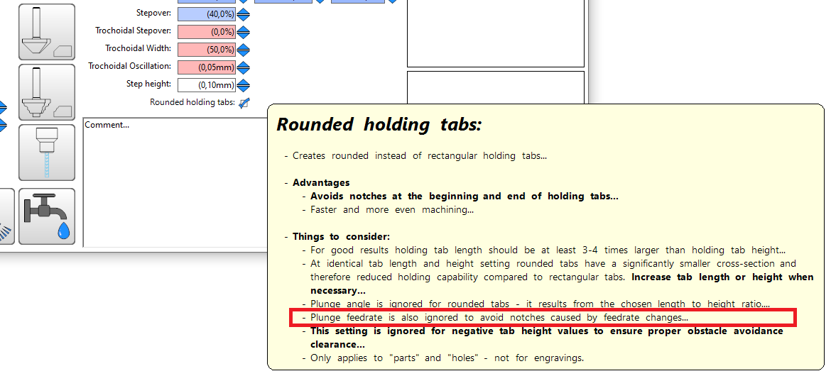
rounded tabs are intended to avoid ugly notches at the beginning and end of tabs by maintaining a uniform cutting speed.
Plunge feedrate is intentionally ingored as those changes also create notches (not as bad as plunging at a 90° angle, but still usually very visible):
Christian
It even ignores it at the initial plunge nowhere near a tab, If that is your intent that is okay I will just use regular tabs. In metal the plunge is much slower than the cutting rate.
The next thing I noticed the plunge on helical holes the plunge seems very slow for some reason. I even tried to use drill, then hole to open it up further and if there is a ramp angle it seems extra slow.
I can’t seem to fine tune the downward speeds properly. In wood and plastic this is not a big deal but metal is extra sensitive.
Why? Did you miss the point of the v11 video (Estlcam 12 Alpha - #117 by dalrun) promoting the restoration of the Add/Insert function or the just above mentioned adding a custom SVG engraving to a specific location on a reusable (otherwise ready to machine) .e12 project? How do I do either w/ v12? The registration of the Added/Inserted file to the existing project is the most important aspect.
Thanks, that explains why I have been having a problem.
@christian-knuell is there any plan to add “Move DXF” like in V11? Its nice to be able to add the file but I cant find a way to move it. Right now I have to create the tool paths and then move those. It makes for a very easy to get confused situation.
Also when I have a bit set up for Trochoidal Milling and also have the Drill section set up it ignores the tool path depth for drill and just does a straight plunge with no pecks. Is there something I need to do differently for this to work?
With the move tool selected, use the Right-Click to select the DXF parts
You can mix and match Left and Right clicks and move the toolpaths and the drawings together.
The workflow is a bit clunky though. I do wish it was a bit easier to move between selecting and moving things
Damnit. I keep forgetting about all the left and right click stuff. Thanks @Michael_Melancon
Hopefully @christian-knuell has an answer about the drill function though. I know someone made another post about it as well
That was me. I have the same issue with pecking…
oh…and also I see now
not just you or me. @RegPye too lol
edit, you beat me to it LOL
If the file opened with Update is an updated version of the original file, v12 does not have the v11 limitation of changes having to be in the original X+,Y+ quadrant and I stand corrected… Any additions outside X+,Y+ will require a Zero : Margin = 0 to recover the left-bottom origin.
Maybe it’s a language issue, but replacing one version of the file with an updated version (VS “replaces one drawing with another one”) is the only practical use for the Update function. Anything else will require paying attention to the embedded source file origin.
Update is a much better way to add objects to a project than the v12 Add function because the objects can be added to precise locations anywhere in the drawing. How is Adding objects that sit atop the X axis (original or reset?) and 10mm to the right of the original drawing elements a useful function?
You can move them wherever you want after addig them. How is that a problem?
Yes you can use the Move function, but how do you move them to “precise locations” when you don’t know where they are, i.e. what their precise location is relative to the origin point?
…How did you read and reply to my post within seconds?
…with the v11 Insert function there is no need to Move anything and, once the origin of the Inserted file (e.g. that custom SVG engraving) is set, the file is editable and reusable (just like the saved .e10).