You can measure by clicking and holding the middle mouse wheel
…
Then use 11, you can use both. ![]()
1 Like
Because of changes/losses in v12 I am doing just that. The only thing I currently use v12 for is setting my origin point. I love my new center finding macro (so much faster and more consistent than manual probing) and was starting to think about how I might live w/ the v12 out of order Carve pocketing (to have the importance of that issue, and apparently this one, not understood is disheartening) by switching doable tasks to v12. The Add function not working like Insert has me back to thinking I’m stuck w/ v11.
I found a possible solution that may be of some help.
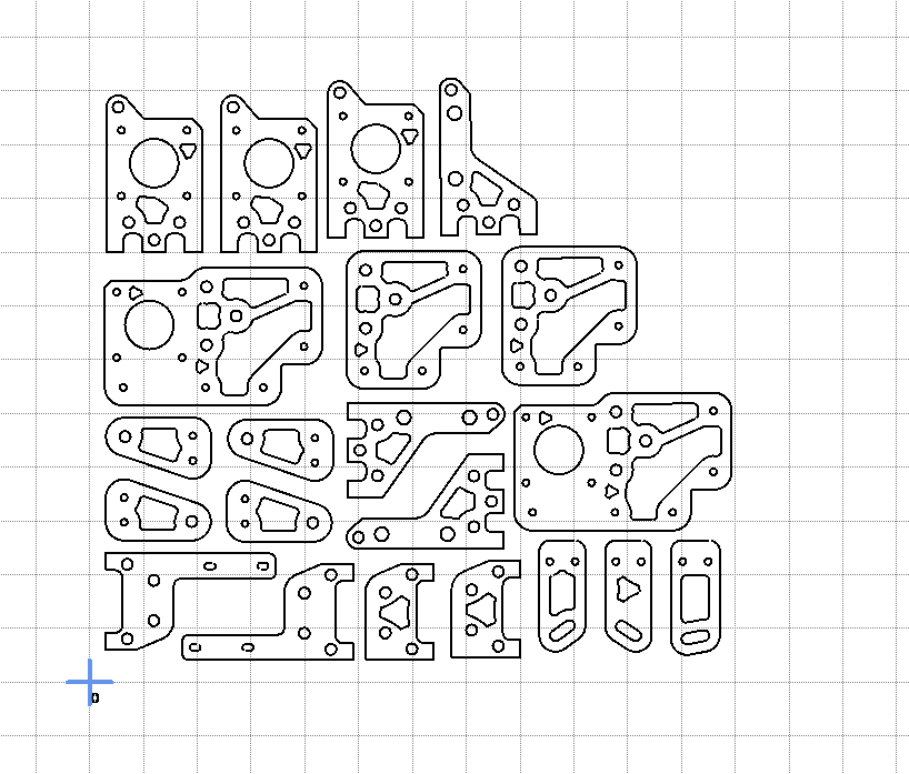
I had a CAD file with multiple elements in it, all situated where I needed them.
I wanted to add another element (just for testing) and I used the add function.
When I did that, the original file shot off to the left and down.
What I did then was to start over with my CAD program and I drew a bounding box around the elements of the first drawing, (added a line box) loaded it into Estlcam again and then proceeded to add the other element as before.
Once again the first CAD file shifted off to the lower left again, but this time I had a bounding box line that I could easily and accurately position the zero point at the lower left corner
I could then add and then shift the added element to where I wanted it within the original CAD drawing layout,
2 Likes
I allways draw a small cross to set the milling origin in the original drawing. this is because I often mill text into planks of uneven shape and use the center line as a reference. In combination with a good layer stucture it is not neccessary to add “elements”
I usually add a small circle to the centre of a CAD file for the same reason. Most times I use crosshair laser to position the tool for quick jobs that don’t need perfect accuracy, like for cutting a keyhole for hanging a plaque.
This small circle becomes my reference point that I can come back to if needed for setting up again. I physically draw a diagonal cross on the stock with a pencil to reference the crosshairs
1 Like
-
The New objects (and E12 paths) may not overlap the existing project elements at all. They can be optional and or customized components that are designed to register with the existing components (inside the initial bounding box). Retrieving the V11 e10 default requires manual measuring and two Moves (…selecting the paths and then using a D + click to include the drawing does it in 1) in V12.
-
What is “cumbersome” is a matter of perspective. The only use case where adding a new file some unknown distance to the right of the project origin is less cumbersome is if you don’t need that file to register with the project origin or to be located at some specific location relative to the project origin.
If the location of the added file is important, the easiest first step is to manually measure its location relative to the project origin and (…click the drawing with the D key pressed to Select it so you can) Move it to the project origin, i.e. to where V11 would have put it in the first place. The file is now where it needs to be or can now be moved to the desired coordinates. While moving the file directly from the default offset location to some desired X,Y distance from the project origin is possible, it requires some math and - at least in my case - is more error prone.
As others have covered, the file needs to include an origin marker (bounding box, L, circle, etc.) so that the measuring tool can be used to manually measure the distance Estlcam has chosen to offset the file origin from the project origin. With v11 that registration marker is the origin point embedded in the file (DXF or E10) or top-left of the page (SVG).
As others have noted, the V12 project origin can randomly change (even when all work is done in the default X+,Y+ quadrant) when adding files. Including an origin marker in all project files makes it easy to reset it (e.g. before adding another file).
This bit me a couple days ago, as I would not have expected my manually set Zero point to change by adding an additional drawing that is placed out to the right.
I was working for a long time with a file layout like this
After making a few cuts, I wanted to check the size of a new exported part against one that was already there. Adding that file caused my zero point to be completely recalculated.
That’s when I realized that (stupidly of me) I had not saved the file in a bit, and there is no undo to get it back to where it was.
My only recourse was to spend a bit of time, going out out to my machine and taking measurements on the stock and manually trying to place the zero point in a “close enough” spot to hopefully not cause an issue on the next piece I cut out.
It definitely feels to me like an Add operation should not change where the Zero point is in relation to all the drawings that already existed before the add.
3 Likes
He only added it because it was asked for and said it might be clunky. ![]()
![]()
That’s fine. Just offering feedback. That’s the only way software gets better for the users.
He can fix it or not, but it’s good for developers to see actual use-cases so they can understand the impact.
3 Likes
Hello,
the origin change when adding files is unintentional.
I’ll fix this with the next update.
Christian
5 Likes
Hello,
regarding the add function - the way I intended it is this:
- You have a file with some parts, and another file with other parts - and want to machine both in the same Estlcam project.
- You open file 1, then add file 2.
- File 2 will be placed to the right of file 1.
This location is unlikely to be the place you really want it to be - but is a place where it won’t interfere with anything from file 1 which would make selection difficult. - Now you can use the “Select” function, hold “F” key (“file selection”) pressed, click on a shape belonging to the second file - this will now select all shapes of the second file…
- Then switch to the move function…
- And now you can move the second files shapes to wherever you prefer.
Edit:
One of the main reasons to disregard drawing origins when adding files is that origins are sometimes really “f…ed up” - especially if the drawing is derived from a 3D model. Those are often “floating in space” at rather random locations. It is hard for Estlcam to decide if a far away object (sometimes in the range of several meters away from drawing origin) are placed there intentionally - or randomly. Such objects can become almost impossible to find after adding a file if they are small and if the file origin is kept.
This is also the reason why Estlcam begins by setting origin to the leftmost, front border when opening a new file - the origin in the drawing is often ridiculously far away if the file has been created by some 3D CAD programs.
Christian
3 Likes
If nobody else has no use for the offset, please, at least put the added file at a grid point so that it is at a known location and no manual measuring and by the numbers moving is needed to get it there (…or make the project origin offset settable).
Apparently undocumented: Drag area (paths) then D(rawing or F) key to select both the paths and drawing (.E12 Add or Tile).
Hello,
the origin change is now fixed.
Christian
3 Likes
That was fast!
1 Like
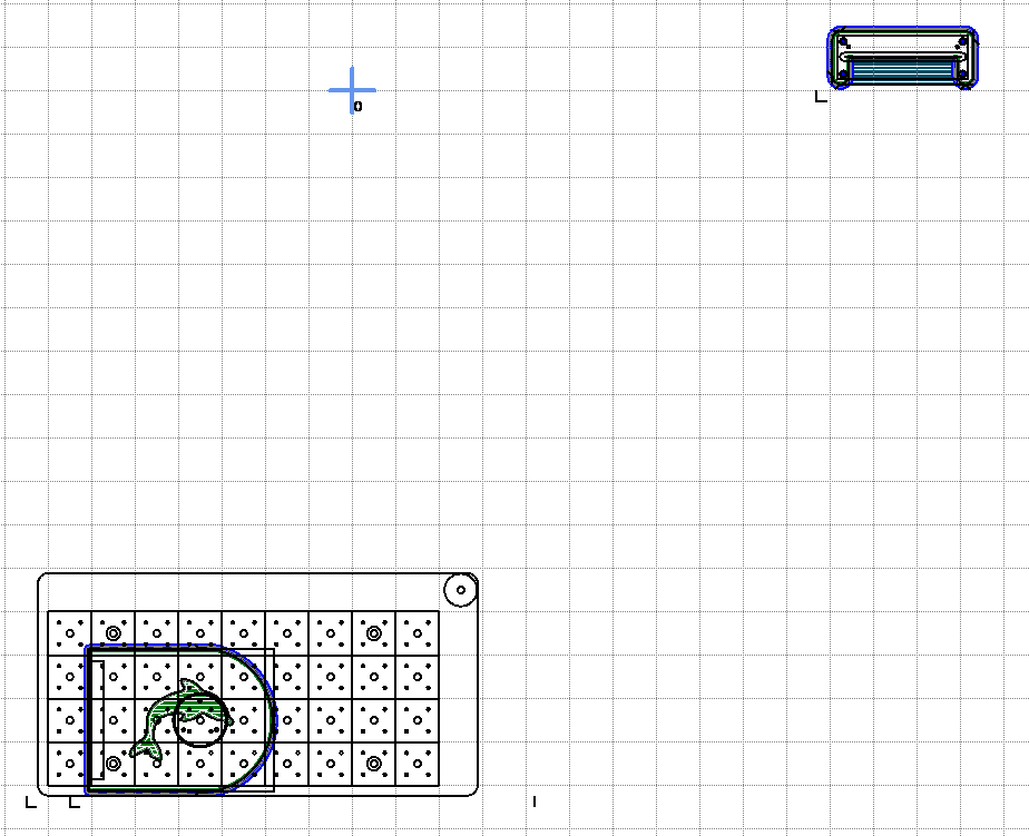
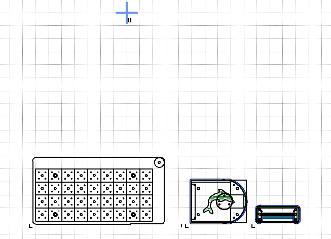
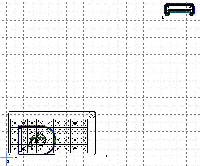
I just got the following w/ 064a (the first Add moved the origin from the bottom left and the second Add used that new origin point)… It’s repeatable in that a different first Add file moved the origin to (at least pretty close to) the same place… If I correct the origin after the first add, the second add shifts it back to that same offset… If I don’t Move the first add or reset the offset origin, the second add is positioned relative to the bottom-left (2nd image).
.
Hello Dave,
I missed that the same issue also exists for project files - not just drawings.
Will be fixed with the next update.
Edit: just uploaded a fix (but did not increase the version number - it is still 12.064)
Christian
1 Like
Re-posted, it wasn’t meant to be a new topic.
While the origin now appears stable, the second Add is still shifting up to the same position as before. This only happens when the first Add is moved from its default location before the second Add… and it only happens if the first Add is ‘Align to grid-point’ dragged into position (I really like that feature), numerical moving is fine.
Thank you Christian (@christian-knuell). I’m not sure why it worked fine today, should I have tried Alt+5 - when and how is that used?
…And the rest should have been a new topic (I’ll get it right one of these days).