My machine can now move much faster, over 200mm/sec in X and Y and over 40mm/sec in Z, thanks to being controlled by a Teensy 4.1 on the grblHAL breakout board by Phil Barrett. I upgraded it to 40 V powering the TB6600 stepper drivers.
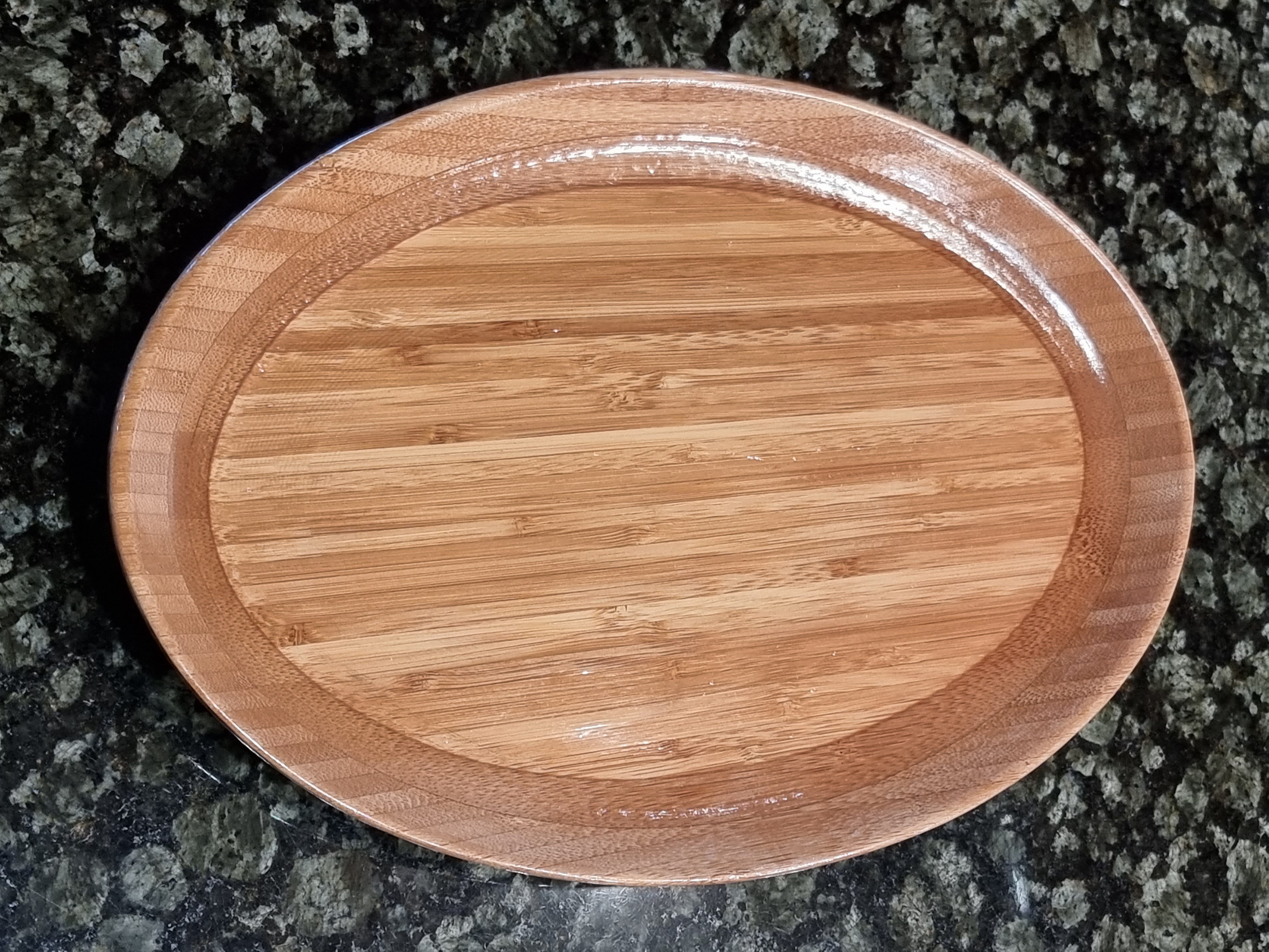
I designed this plate in VcarvePro using the moulding toolpath. This wood is much harder than my previous acacia dinner plate, but the MPCNC did not show any signs of being pushed too fast, even at 100mm/sec with 6.2mm depth of cut.
For those of you who enjoy watching the chips fly, I am sharing my project video album on Google Photos. The videos are not edited and are all playing at actual speed. You can find captions to the slide/video show if you click the i with a circle around it. Photos and videos of the whole carving process: https://photos.app.goo.gl/ZUGgq4PokTSQPeYD9
I am one of those who can’t not watch the video of a Cnc in action. Thanks for sharing! Like how you got the speed up for those passes with the ball end.
I did notice the rapid back and forth to home before each gcode, and it actually hit the stock once doing that. Do you know why your rig does that? Usually it is cam doing that, but grbl does have start and end gcode too. I got lucky early on when that happened as well and did not break a bit, but found out why and fixed it soon after as I imagined a clamp would be my next victim.
Good observation. I made sure rapids would clear the stock and screws, but not the wooden pegs. It went through one like air!
I have some setting to start and end at the origin in VcarvePro. I find it helpful to see if I have lost steps or forgot to home the machine properly before it starts cutting.
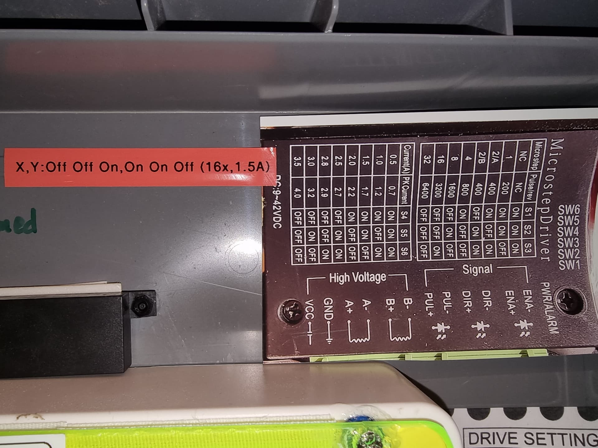
Yes, that would overheat them. I use 1.5A, On On Off, and bolted heatsinks to the top of the steppers.
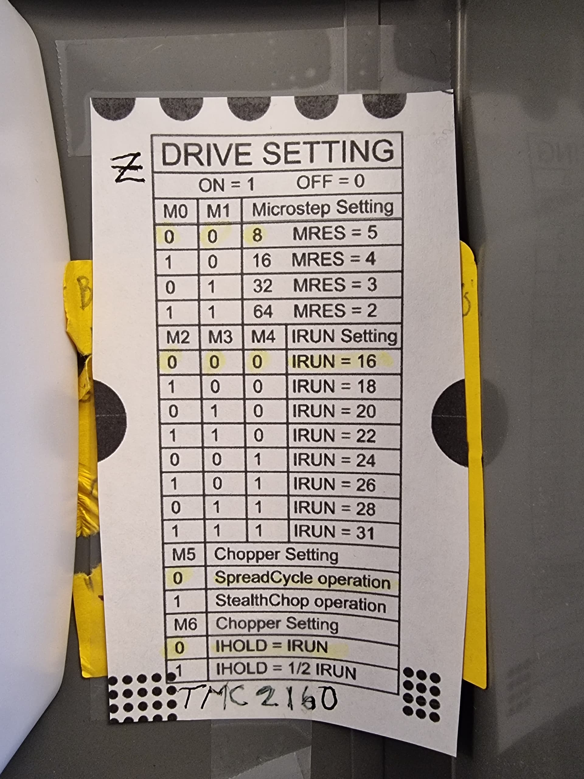
I am using a different controller for Z stepper, the TMC2160, which has more protections. This stepper has a water cooling heatsink strapped to it. (tapping into the spindle’s cooling system)
I think so but I am not sure. I use the lowest number of microsteps that makes sense. If a microstep is less than 10 micrometers, it seems pointless to me.
In more practical terms, you can go faster (in mm/s) by using fewer microsteps, if you are limited by the clock rate of your controller board sending out the pulses. If you are using an Arduino Mega (13MHz) this is a real issue. For the Teensy 4.1 or ESP32, it is probably a non-issue.
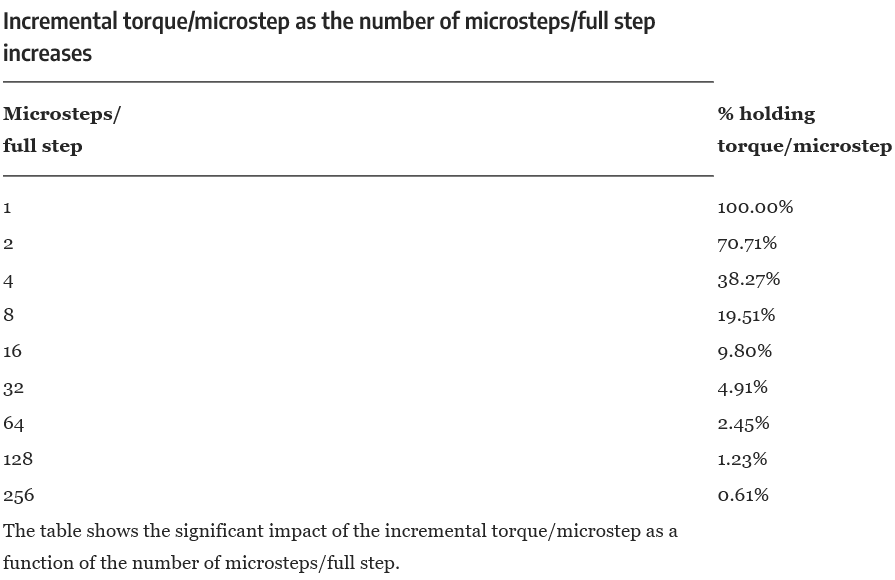
You might want to look up a torque test. Those charts are all over the place but real world tests seem to show otherwise. This comes up from time to time. I do believe what you are actually looking at is one step at that size, not real world use at that resolution.
Can you use less steps/mm, sure, but I doubt there is any real world significance in our case. We played with it and I did not see any reason to do so. I would jump all over a free upgrade.
Hmm, interesting and good to know. I ran my Primo with those settings for 2.5 years. When I tried to do 20 000mm/min the drivers skipped steps though and I was thinking it might not if I used 16x. I don’t know at all if that matters and I don’t want to use that speed regularly, I just thought about it and wanted to try to achieve it.
I now have the settings at 8000mm/min as max and movement with inertia dialed down to 40%, up from 3000 and 85%. This works well without the table shuddering when moving. I would just like to know where the limit is.
For that you can look up the RPM torque curve. What you just showed is a holding or possibly single step torque.
RPM drops off power significantly.
When doing rapid tests make sure at some point you touch the gantry while it is moving to see if there is any power left. I can fly mine around but any tiny slightest touch causes it to let go. So I dialed it back. I prefer reliability rather than save a few seconds with rapids.
That chart is completely misleading or misunderstood.
A whole step sends 100% of the max current through loop A, and 0% to loop B.
A half step does that same thing when it is on a full step. But at the half steps, it sends 70% of the max current through loop A and 70% through loop B (actually using more than the max current total).
A quarter step does that same thing at full and half steps. But it sends 38% to one loop and 92% to the other.
At 1/16th stepping, the first microstep away from whole is: 9.8% and 99.5% to the other.
The math is pretty simple:
Coil A Current = sin(90/microstep)
Coil B Current = cos(90/microstep)
This chart only shows coil A current. It doesn’t show you coil B current.
The actual chart should look like this:
microsteps
% max current in Loop A
% max current in Loop B
1
100.00%
0.00%
2
70.71%
70.71%
4
38.27%
92.39%
8
19.51%
98.08%
16
9.80%
99.52%
32
4.91%
99.88%
64
2.45%
99.97%
128
1.23%
99.992%
256
0.61%
99.998%
That still doesn’t tell the whole story though. Because as you are cycling through the microsteps, you are slowly moving between those values. So the 16 microsteps you would take between two whole steps look like this:
microstep
coil A
coil B
0
100.00%
0.00%
1
99.52%
9.80%
2
98.08%
19.51%
3
95.69%
29.03%
4
92.39%
38.27%
5
88.19%
47.14%
6
83.15%
55.56%
7
77.30%
63.44%
8
70.71%
70.71%
9
63.44%
77.30%
10
55.56%
83.15%
11
47.14%
88.19%
12
38.27%
92.39%
13
29.03%
95.69%
14
19.51%
98.08%
15
9.80%
99.52%
16
0.00%
100.00%
Half of those values are exactly the same as the 1/8th microsteps sequence. It is just trying to smoothly transition from being aligned with one magnet face to being aligned with the other. Newer drivers, like the TMC 2209s we use on the skr pro actually move at 1/256 microstep resolution, but only take 1/16 microsteps input. They are cycling fast enough to interpolate between the input steps, and generate even smoother transitions between the 1/16 microsteps without having to bog down the microcontroller.
You could argue that you won’t see the difference between 1/16th and 1/32nd microsteps. You could argue that the flex of the motor shaft (and the bit and everything else in between) cause errors much larger than 1/16th of a whole step. But arguing that you lose torque with higher resolution microstepping is a myth.