Wow, this is awesome! Thanks for the updates and info!
So a bit more incremental progress to report…
While I’ve been procrastinating (er, umm, I mean researching aluminum cutting feeds and speeds), I decided to do a bit of cleanup on a few items.
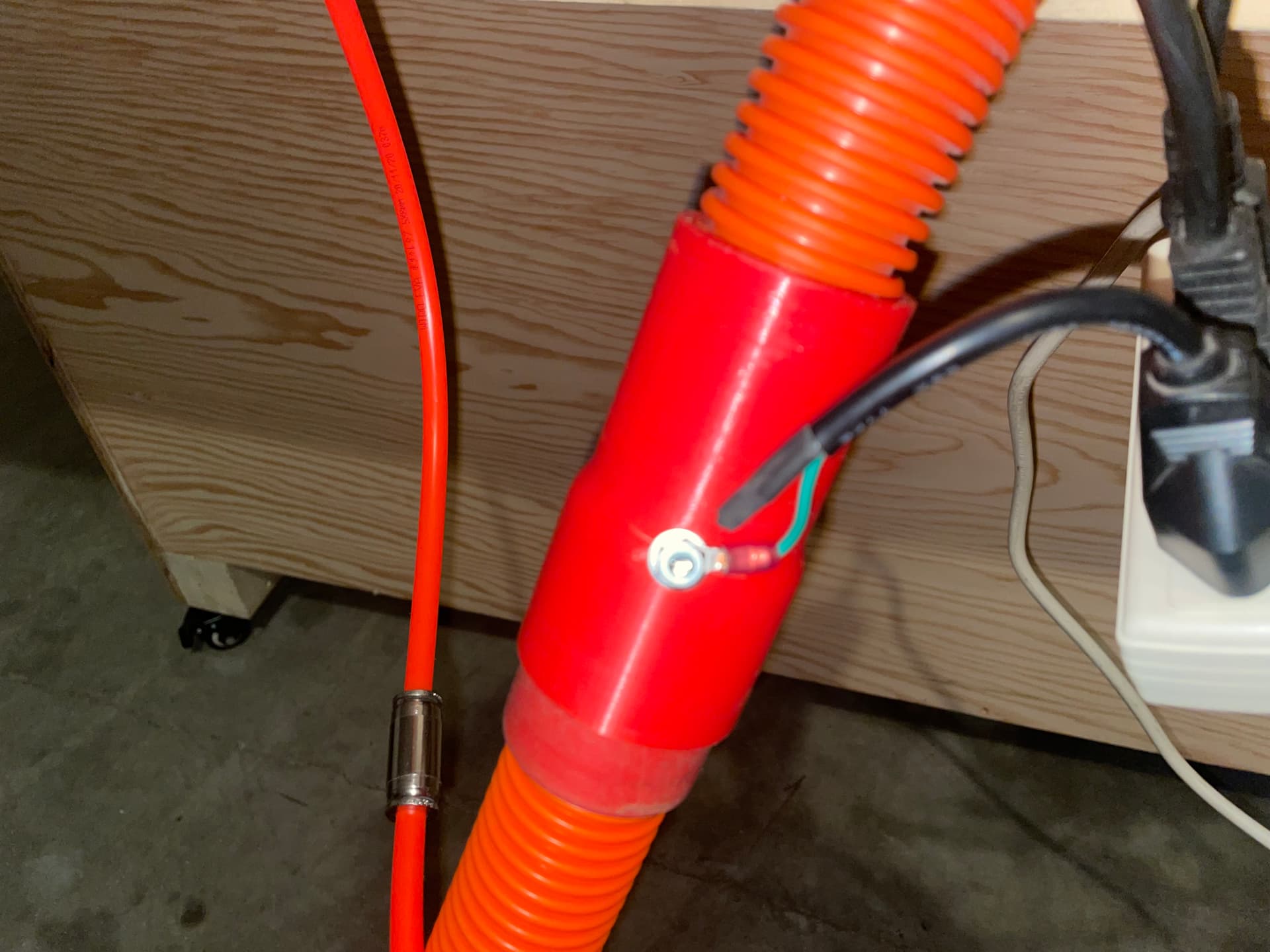
First of all I mounted a power bar with a kill switch, and a shutoff valve for the air supply to the mister assembly. I put it near the future Min X Min Y location (I’ll be converting from Portrait to Landscape shortly) so that it will be close by when starting cuts.
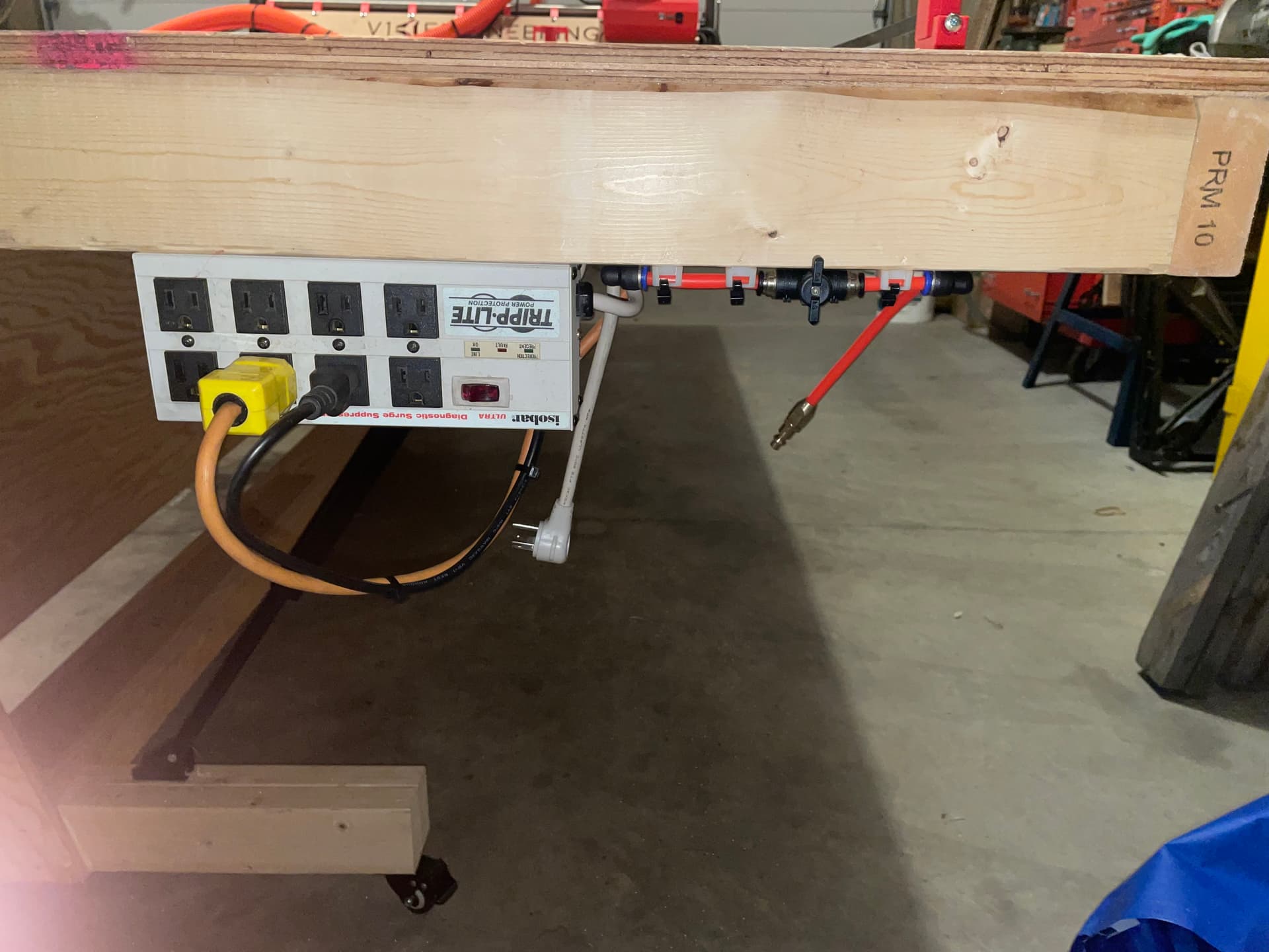
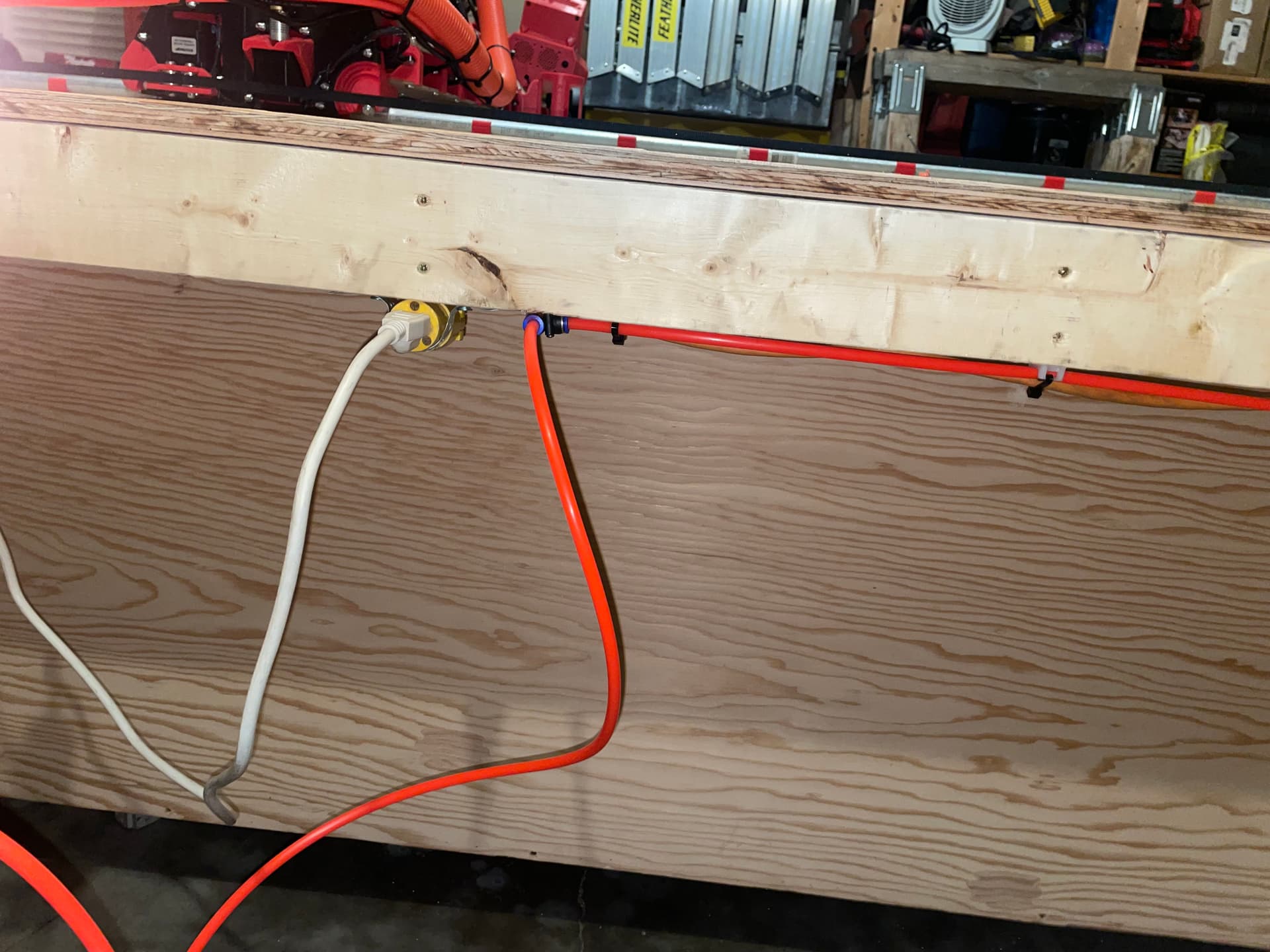
From there I ran some air hose and an extension cable to the midpoint of the rear of the table, and made it so that everything can be quickly disconnected.
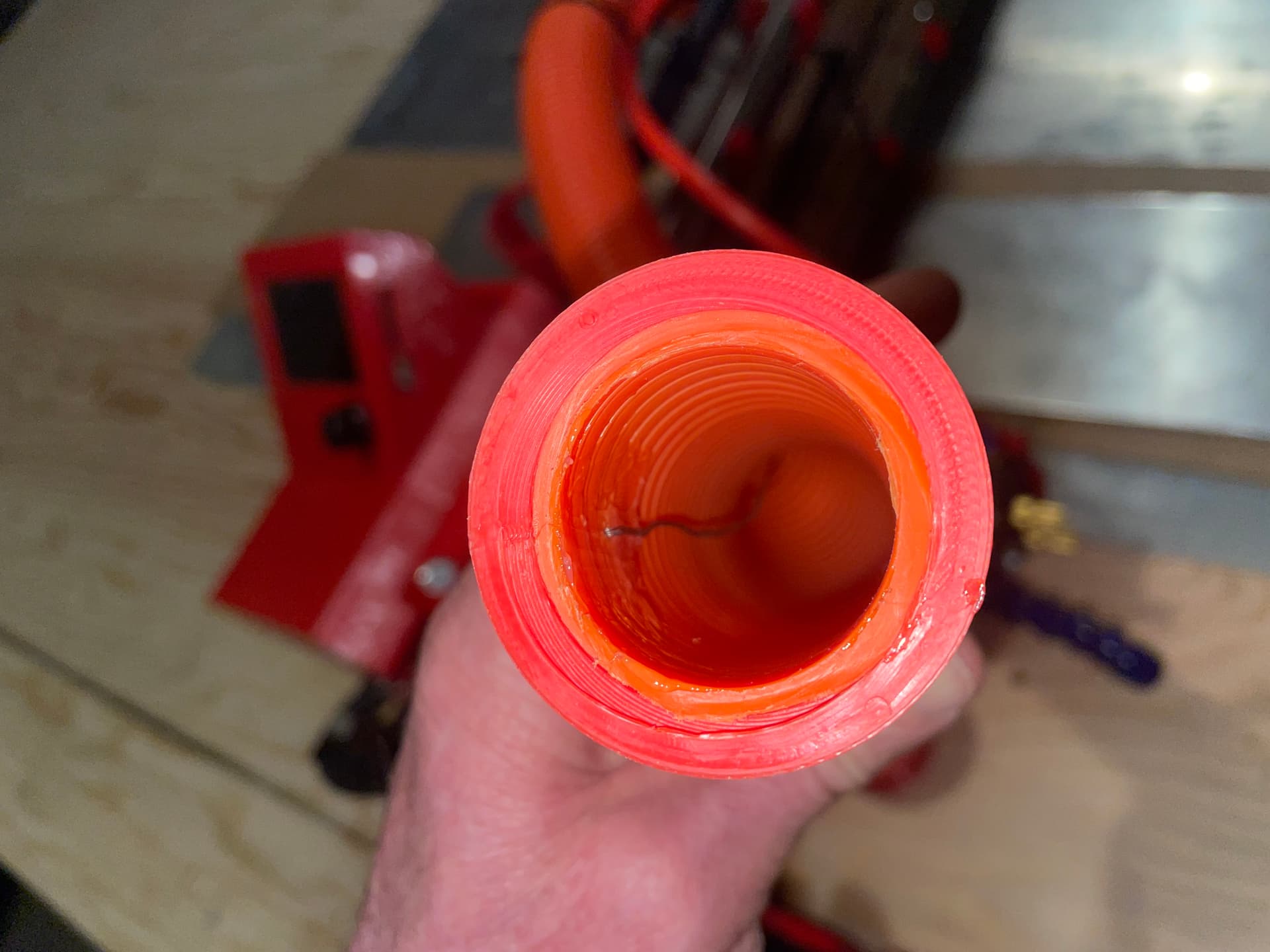
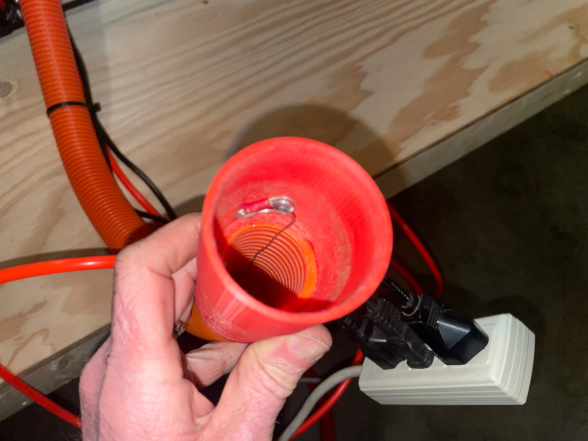
Next up I installed a “drain wire” inside the section of vacuum hose that connects to the LR3 for static grounding.
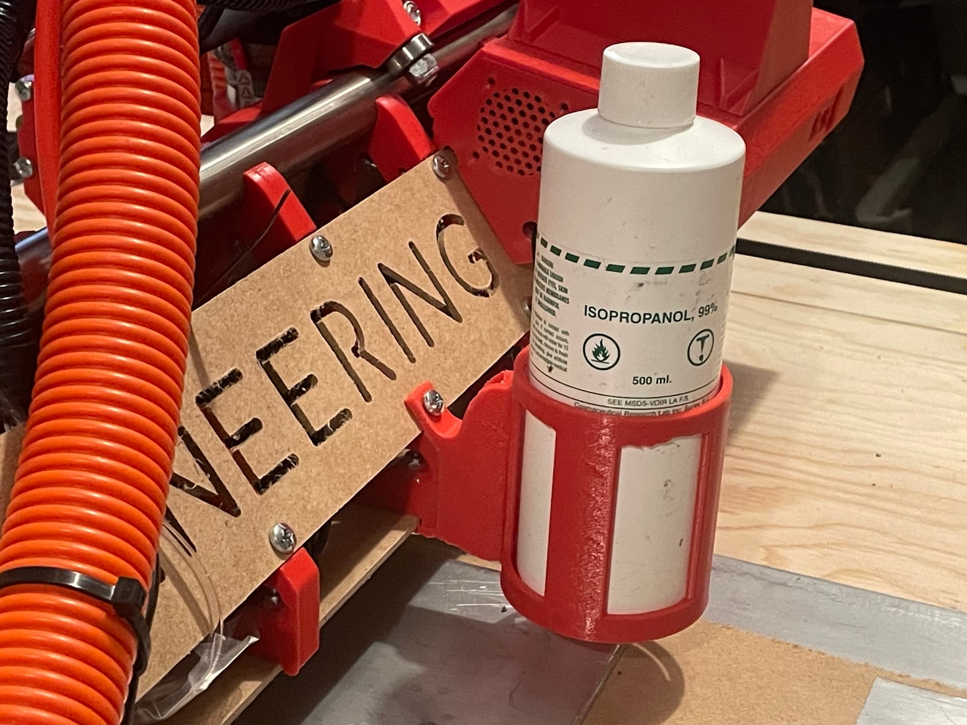
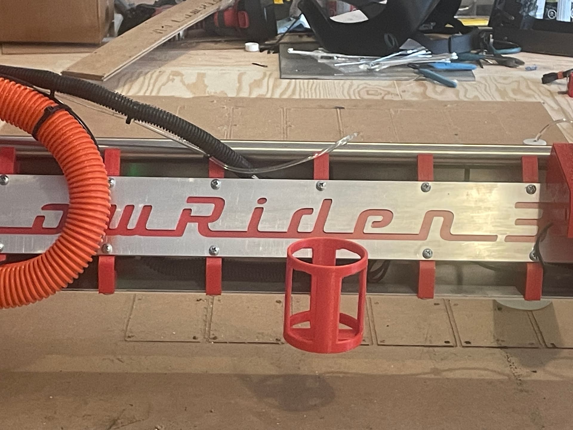
Also I designed and printed a bottle holder for the Iso-Propyl Alcohol (IPA) for the mister system.
Coming up, I really have to get off my a$$ and start cutting the aluminum struts, followed by new aluminum XZ and YZ Plates.
3 Likes
Progress!!
After a lot of procrastination (er, um…I mean research), I think I have sorted out the feeds and speeds for cutting my struts. I used G-Wizard (CNC Kitchen) to come up with the following suggested rates for 2.5mm DOC, Single Flute 1/8" mill, with 0.35mm finishing pass:
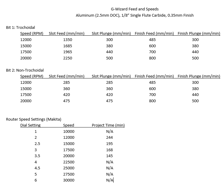
Any comments/sanity checks are more than welcome.
After a bit of a misadventure trying to figure out EstlCAM parameter sets, I managed to create and save the g-code for a variety of different speeds. Tomorrow (or at least this weekend) I hope to do some air-cuts to test for excessive vibration and shaking at different speeds, and then hopefully start making some aluminum chips!
2 Likes

Even at 2250 mm/min, there really doesn’t seem to be any concerns about vibration or shaking, at least with the air cut. I’ll try actual cutting as soon as I get a couple of hours free to devote to the project.
1350 mm/min @ 0:00
1685 mm/min @ 1:12
1965 mm/min @ 2:12
2250 mm/min @ 3:15
2 Likes
Great progress, then a great setback…
The day started out well, with the first cuts in aluminum. I went with the 20000 RPM settings, because it said that it would only take about 2.5 hours.
(turn down the volume for this video)

The chips looked really good, mostly smaller segments because of the Trochoidal milling, but some good spirals in there as well…

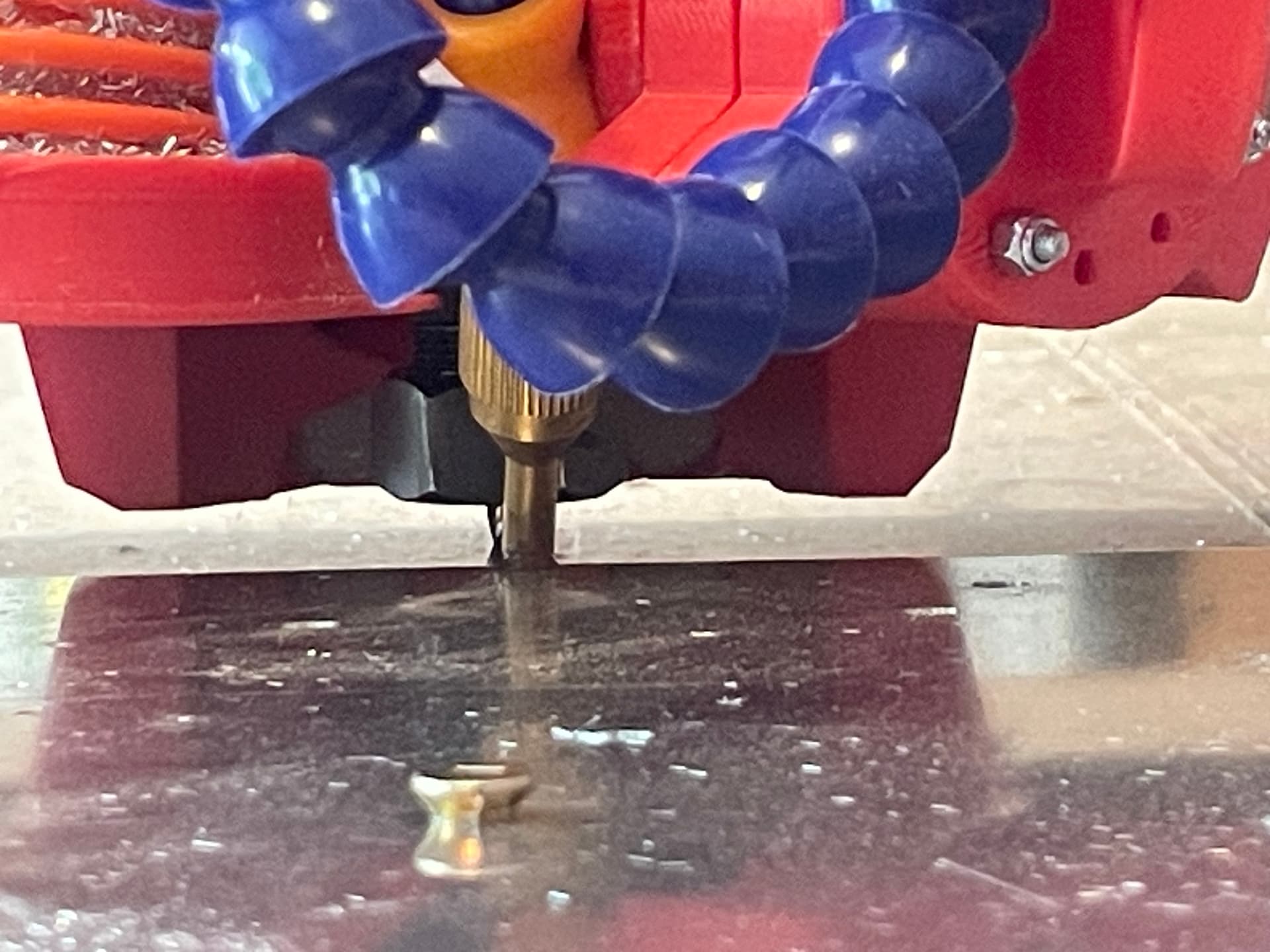
The AIr Mist system worked really well, and blew all of the chips out of the cutting path quite well.
I made it all the way through cutting all of the screw holes, as well as the first strut part, when disaster struck…
I put screws into several of the strut screw holes to secure the material to the spoil board during cutting. I had EstlCAM Clearance Plane set for 3mm.
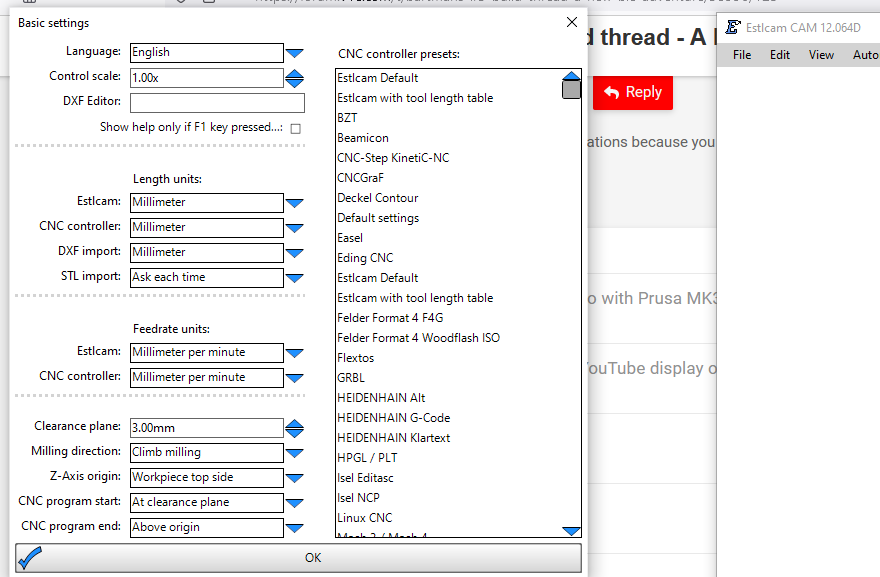
When the first part was finished, the gcode called for a rapid move to the next part. Unfortunately that path was right over (through) one of the screw holes that had a screw in it, and there was contact. I had used a mix of 1/2" and 1" screws, and fortunately the screw in question was one of the shorter ones, so it pulled out rather than snapping the end mill. However the resulting loss of steps caused the router to start cutting into the just-finished strut part.
So the next step now is to re-run EstlCAM to produce a new gcode with a 5mm Clearance Plane, use Notepad to remove everything up intil the start of the second strut part, re-home X & Y, reset Z using the touch plate, and try again.
I did notice a couple of issues during the initial cut:
- Every time my compressor kicked in (8-10 minute intervals), the ensuing voltage drop resulted in the router speed decreasing enough that I could hear a change in the cutting. The chips still seemed ok, but it sounded like it was struggling a bit.
- EstlCAM estimated that the whole thing should take 2.5 hours, but cutting the holes and one of six struts took over an hour, so the actual time is more likely going to be closer to 5-6 hours
More updates once they happen
2 Likes
If I’m not too late for a suggestion I would go higher with your clearance plane. Always better to have too much than not quite enough. I was using screws with 3D printed washers for the V5 parts and I believe I set mine at 10-15mm. Way more than I needed but never once did it get anywhere near a screw lol
1 Like
I was going to say the same as I was reading it. I keep mine at 10…for peace of mind
So I made the changes noted above (and increased the Clearance Plane a few more mm as recommended), and restarted the cut. Before doing that I checked the end mill and noticed a bit of aluminum welding to the cutting edge, so I changed out the end mill for a new one. Probably happened when the mill tore into the material and I had to hit the emergency stop.
It all went well for about 90 minutes, and then the mill snapped off. Kinda surprising, because the material was well secured (so no chatter), the air mist (IPA) was keeping the slot free of chip buildup, and the sound of the cutting was consistent with the previous 2.5 hours of cutting.
I may need to pick up a few more end mills before I start up again, and the program ran for a few minutes before I paused it, so I will probably have to figure out where in the gcode the mill broke, and edit to restart a few seconds before that point.
Only mildly annoying, and it is giving me a great opportunity to learn about editing gcode. Also gaining more experience with every hurdle. Pretty soon I might even have a clue about what I am doing! ![]()
4 Likes
Well where did those last six weeks go? Time seems to accelerate, and progress on the LR3 seems to creep along.
I ordered a few more end mills from V1E, then edited the g-code to resume the cutting where the previous effort left off. I managed to finish the cuts without breaking or welding aluminum to the new end mill, so I have no idea why the earlier one broke where it did.
The LR3 seemed to cut through the 2mm aluminum really easily. I used Trochoidal Milling for most of the cuts, and Regular Milling for the smaller text on one of the struts, and both worked great.
Feeds and Speeds:
Trochoidal: RPM 20000, DOC 2.75mm, FR 2250mm/min, Plunge 500mm/min, Plunge Angle 90, Trochoidal Stepover 7.9%, Trochoidal Width 35%, Finish 0.35mm
Regular: RPM 20000, DOC 2.75mm, FR 475mm/min, Plunge 475mm/min, Plunge Angle 90, Finish 0.35mm
Some video highlights of the non-trochoidal cut:

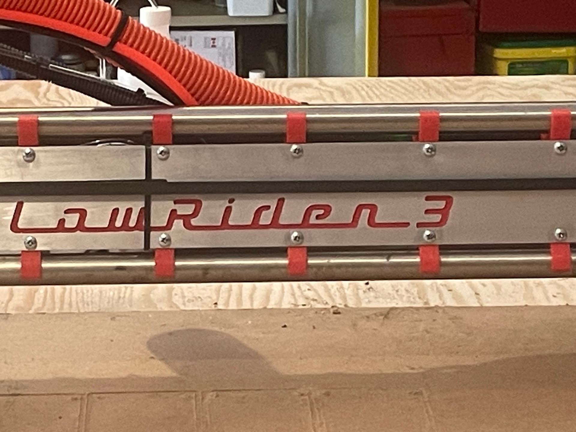
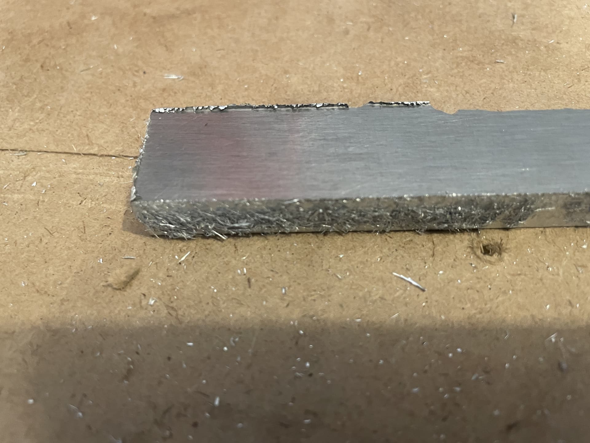
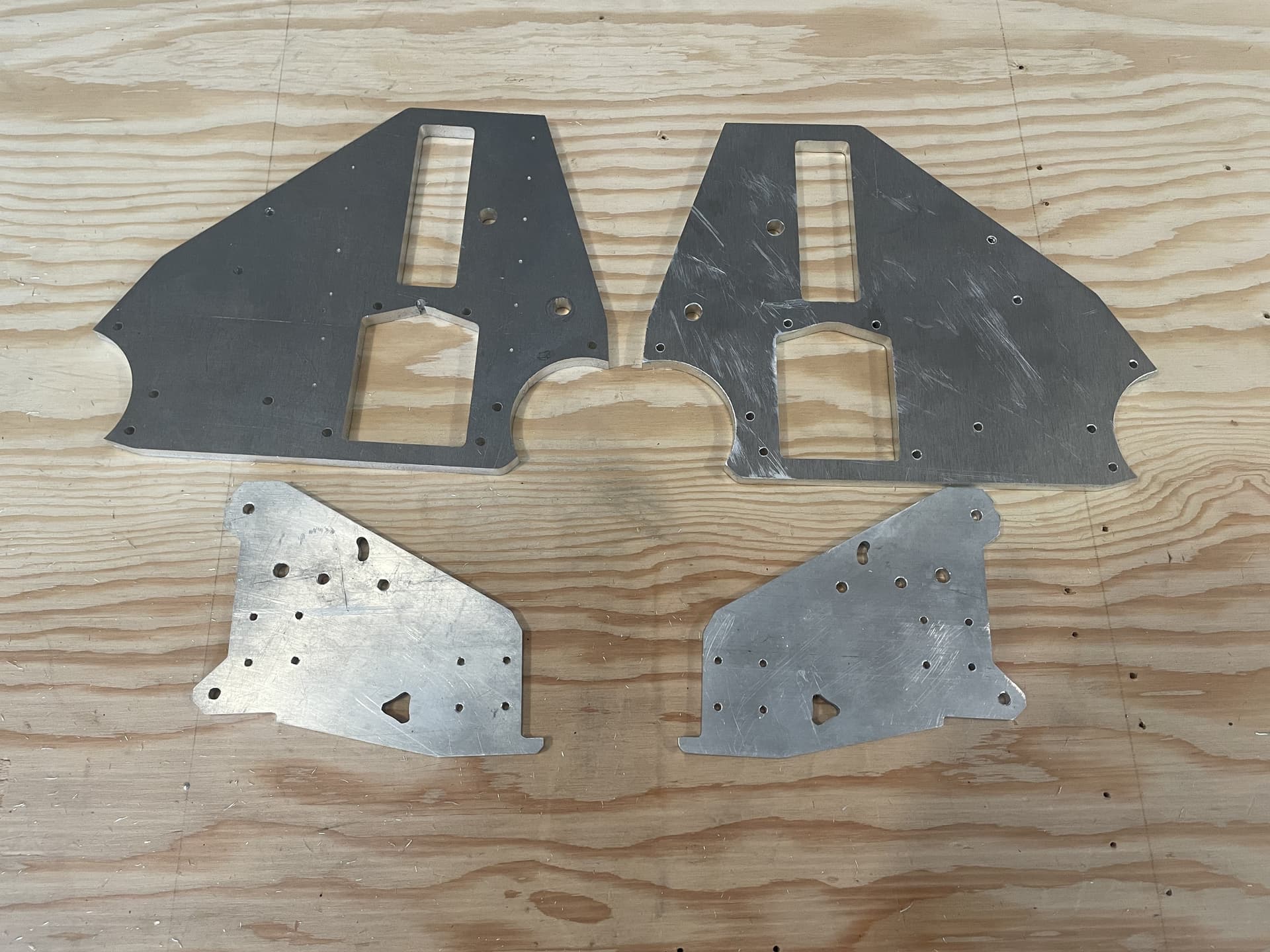
The 2mm aluminum seemed a little thin, and still had a bit of flex when cut to the 80mm width of the strut. So I cut a total of 6 struts, and doubled them up . Two of the struts had the Lowrider 3 logo cut out for the top layer of the front and back struts:

(The top two aren’t as shiny because I cleaned the others with IPA and a ScotchBrite before taking this picture, but hadn’t done the last two yet)
I painted the lower strut and then laid the upper strut on top, for a very nice contrast (at least IMO).


Next up is cutting of aluminum XZ plates (6mm) and YZ plates (9mm). Stay tuned…
9 Likes
very nice!
1 Like
A couple more notes from the strut cutting:
I’m using an old electric air compressor to supply the Air Mist system, and every time the compressor kicks in and runs (every 4-5 minutes for about 2 minutes) the router speed drops a bit, I bumped up the router speed setting about 1/2 a notch to compensate, and it seems to make pretty good chips at both the full and reduced (compressor loaded) speeds.
I also had a couple of issues with the cuts. As mentioned in post #126, I had cut all of my screw holes and just finished the first strut outline cut when the end mill hit a hold down screw and I had to restart the cut. I homed everything and restarted, but for some reason the following cuts were offset in the Y direction by about 1mm. Because of that, when I went to install the front struts, they were contacting and interfering with the XZ plate on one end, rather than having a bit of clearance. I ended up stacking up the last 5 struts and cutting a few mm from one end with a hacksaw.
The other issue was a bit of a goof on my part. My vacuum hose and air line routing was such that the hose assembly was very close to the core at one point on the travel, and when the cut reached the very last strut, the top bearing on the core got hung up on the hose, and it started skipping steps and jumping up and down. I restarted the cut at that point several times, with the same skipping steps and jumping, before I found out why. A quick reroute of the hose and a tie wrap to keep it in place, and the last cut went smoothly after that.
3 Likes
Wow! That looks great.
2 Likes
Re. Bartman's LR3 build thread - A New(bie) Adventure! - #130 by Bartman
You need to enter this in the V1E GO Maker Faire!
Hey, don’t forget to post at least one pic to your new entry, and probably also include the video.
Rather than posting just the link (which does not show pics or video), edit the code text for your earlier post, copy it, and then paste it into the Maker Faire entry post.
1 Like
Thanks Doug - entry post has been edited with a re-post of the above
1 Like
More progress, with some good success and some spectacular (well, at least notable) failure…
The success: the XZ plates came out very well (at least as far as I can tell). I used a V-bit to “dimple” the pilot position for the rail screw holes. and then used a 1/8" drill in a drill press to drill then through. The LR3 worked like a champ, with nice clean edges and round holes. I did find that the holes for the 5mm screws were about 0.05 mm too small, so I quickly hit them with the drill press and the screws go through nicely with just a tiny bit of play.
Now the failure part…
Having had great success cutting through 6.5mm aluminum on a single pass with no real issues, I thought that I would be able to do the same thing with 9.5mm aluminum. I was wrong!
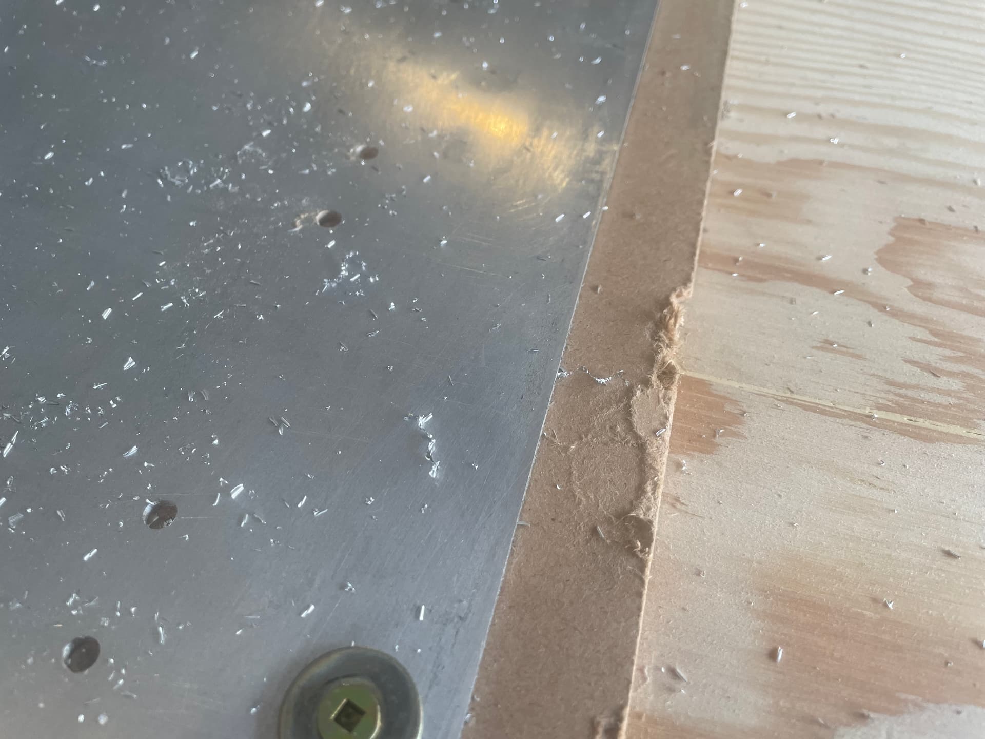
First of all, I noticed that all of the holes had a “groove” cut at one point (different locations on different holes. I first thought that it might be cutting an oval instead of a circle, but it actually seems that the end mill is rubbing against the hole edge when it is retracting. I think that this may be because of poor chip clearing (more on that later).
Later during the cut, everything went for a complete (poop). The LR3 had just finished cutting out the rectangular “hole” for the Z axis lead screw, and was starting its finish pass when the gantry started to buck and shake, and the router motor started to drag down (didn’t quite jam, but sounded like it might).
I hit the STOP button (this is why you never leave these things unattended), raised up the Z axis, and found out that the newly cut out section had shifted and got caught up in the end mill.
I looked closer at the cut out part, and found a lot of “welded” chips sticking to the side of the part. It looks like the chips weren’t being cleared at all, so they were jamming up the slot and getting re-cut.
So there are two things that I will try on the next attempt. First of all, I am going to cut the holes and parts in two passes, rather than one, and I am going to try to figure out if it is possible to move the gantry out of the way between passes so that I can get a vacuum in and clean out the chips. If not, then I might just stand there with an air nozzle and blast the chips out of the holes/slots in real time.
The second thing that I will do is open up the file in F360 and add some screw holes into each of the cut out sections, then screw everything down before cutting out those sections. That should prevent the sections from moving and jamming up the cutting tool.
Unfortunately this experience cost me a really nice 9" x 24" piece of 3/8" aluminum plate. It was a leftover piece from a local machine shop (still cost me $25 CDN), so hopefully I can find a similar sized piece for the next attempt. I’ll probably also try a test cut or two on the original piece, before destroying the new piece as well.
As they say, it is a learning experience!
1 Like
It might be as easy as the endmill you are using died. With metal if you have not got the cuts real perfect it can wear it out real quick.
1 Like
That was the third thing that I was going to do. After this last cut, the existing one is certainly toast.
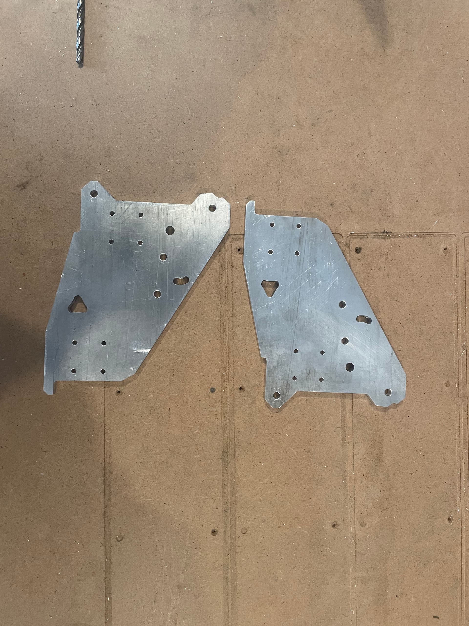
Hurray! I managed to cut the YZ Plates in 3/8" aluminum (and previously the XZ Plates in 1/4" aluminum).
It may not seem like a huge deal from a distance, but I am pretty stoked to reach this milestone!
From where I left off previously, I swapped out the end mill with a nice shiny, sharp one, added a few hold down screws to the sections that would be cut out, and dropped the feed-rate and router speed down just a tad. It cut through like butter on a single pass (well two, if you count the finishing pass), although there were a few issues. They say that we learn from our mistakes, and I must admit that there was a lot of learning and a lot of mistakes along the way…
Issue #1: Because of the thickness of the plate (3/8" or 9.5mm), the air mist nozzle couldn’t really reach the slot, so chips were getting stuck in the cutting area, packing in, and causing a lot of re-cutting. This seemed to be worsened a little bit by the IPA mist, which moistened the chips enough so they clumped together, rather than blow out individually.

To mitigate this somewhat, I added a splitter to my air hose system, and used a hand held air nozzle to intermittently (every few seconds) blow the chips out of the slot. This seemed to work okay, but I had to remove the vacuum dust shoe in order to reach the cutting area with the nozzle, so there were aluminum chips EVERYWHERE (and blown even more places by the air nozzle).
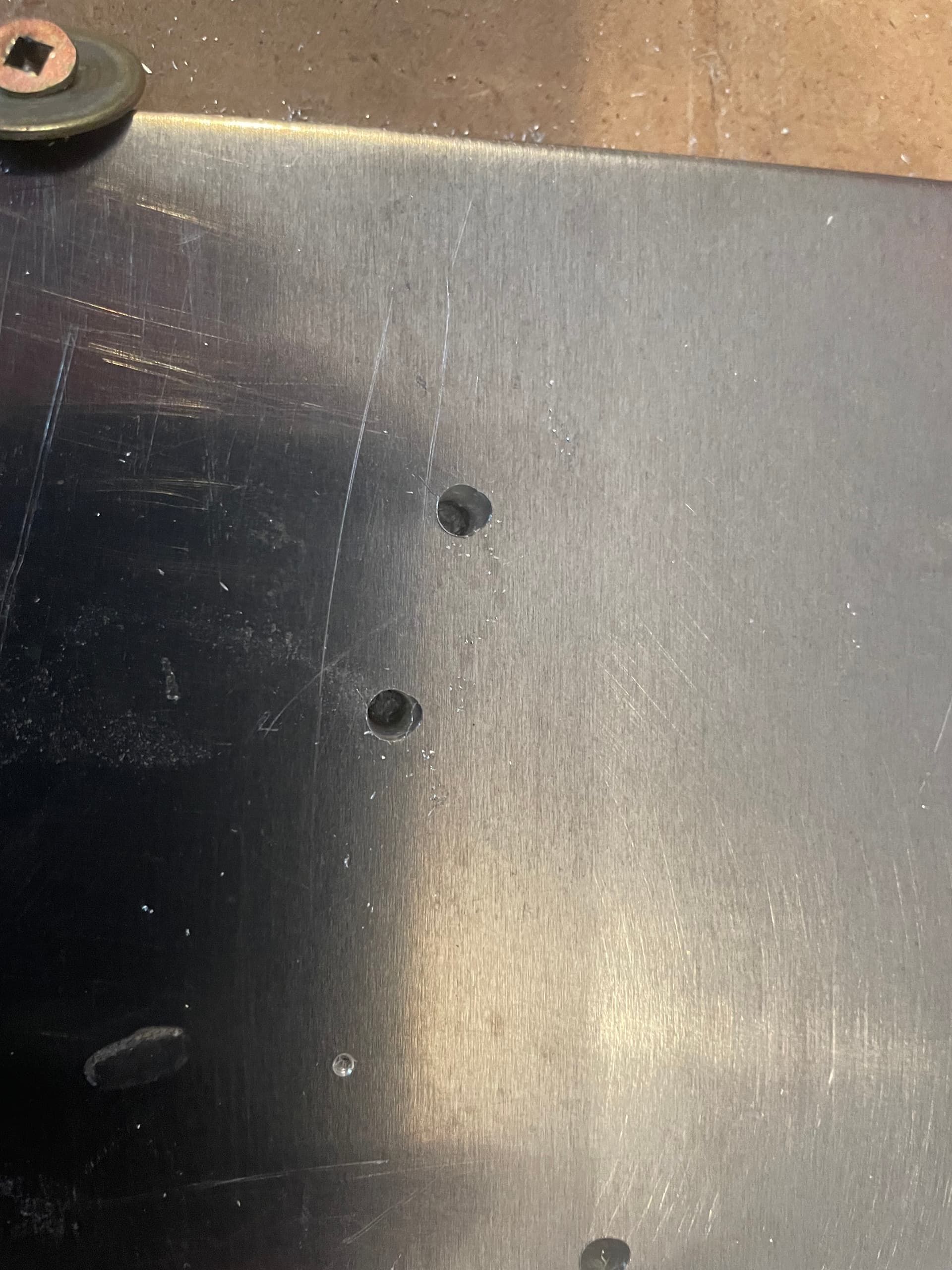
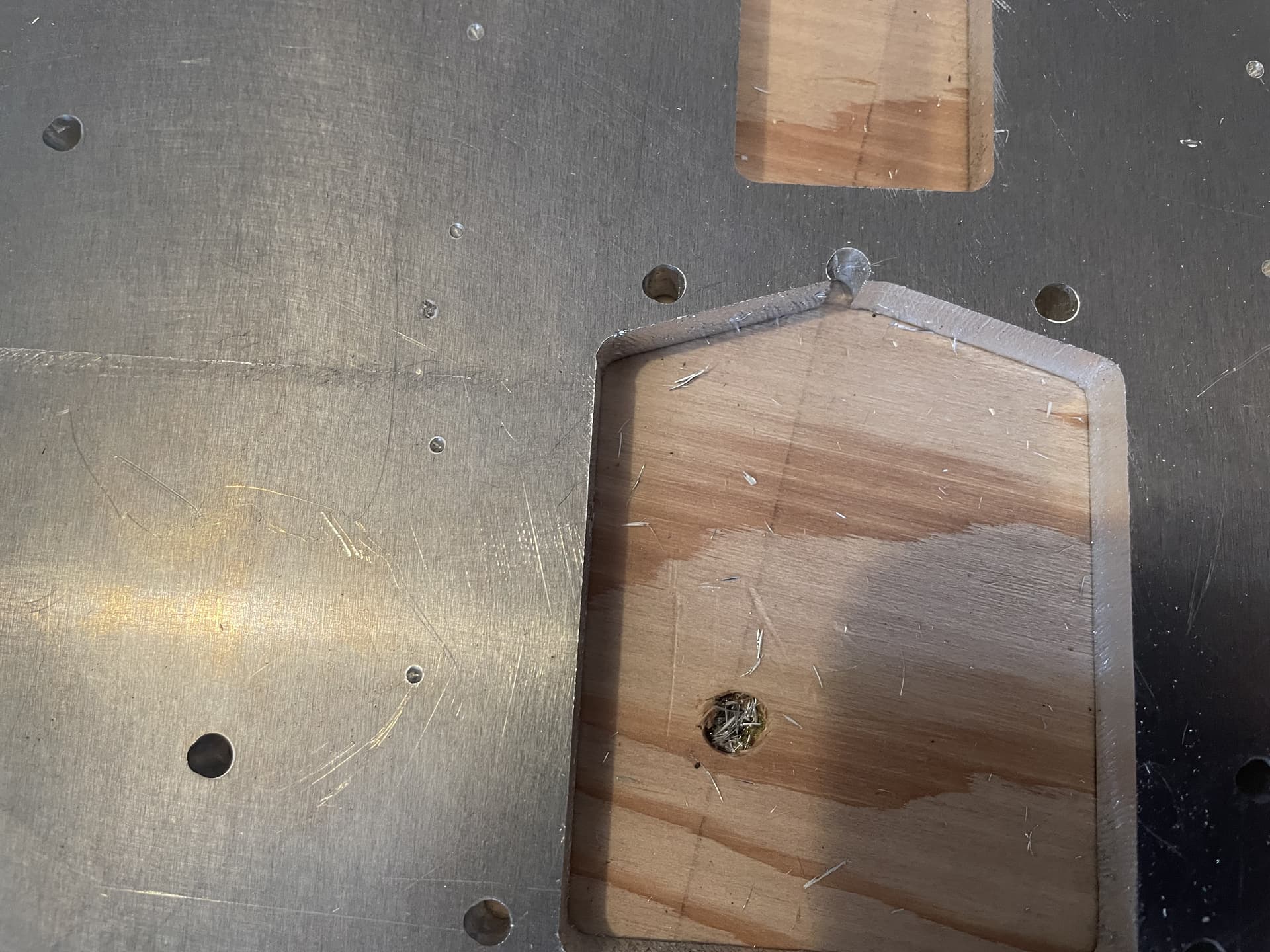
Issue #2: In an effort to reduce deflection, I “choked up” on the end mill so that there were only about 13mm sticking out. The problem was that this meant that the core was only about 1.5mm above the stock, and the previously mentioned hold down screws were sticking up about 2mm from there.
The results were somewhat predictable:
So to correct that I used a drill bit to chamfer the holes so that the screw heads were flush with the stock, and increased the stick-out length to around 17mm.
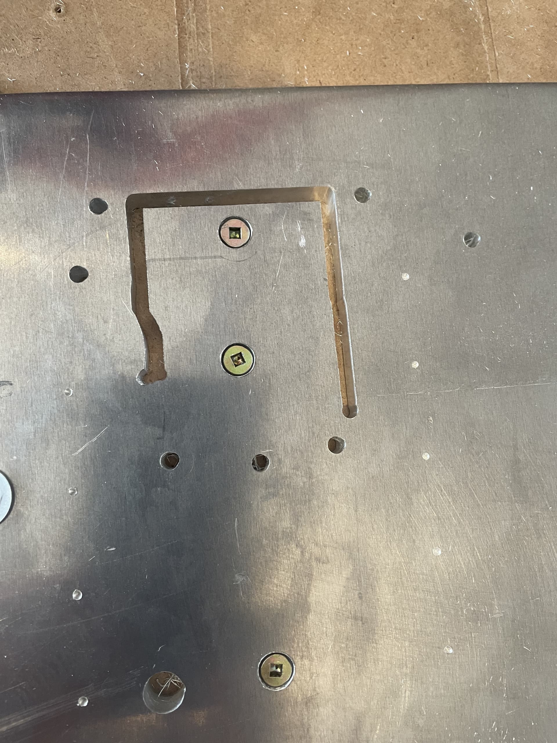
Issue #3: When I added additional holes for the hold down screws to the design in F360 (couldn’t find a way to add them in EstlCAM), I imported the new design into EstlCAM with a different orientation than the original project.
Original:
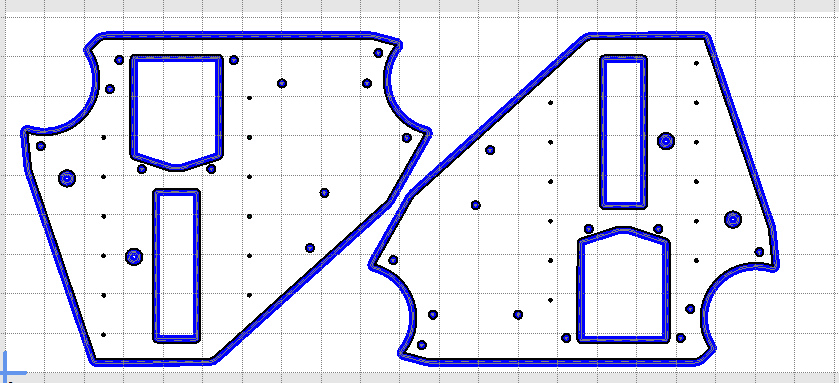
New:
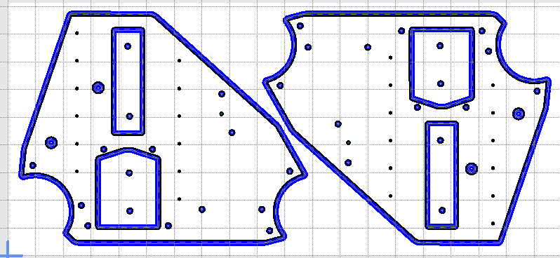
I was originally planning to redo the whole cut using a new piece of aluminum, but then decided to continue cutting the same piece, not realizing that I had flipped the design. I ended up only cutting one hole in a place that it shouldn’t have been before I noticed this and stopped.
I haven’t decided yet if I will re-cut both plates using new material, or live with the imperfection as a reminder to check things twice before restarting a cut. If I go the second route, I could probably use some metal epoxy to fill the gaping hole so that it doesn’t look quite so glaring.
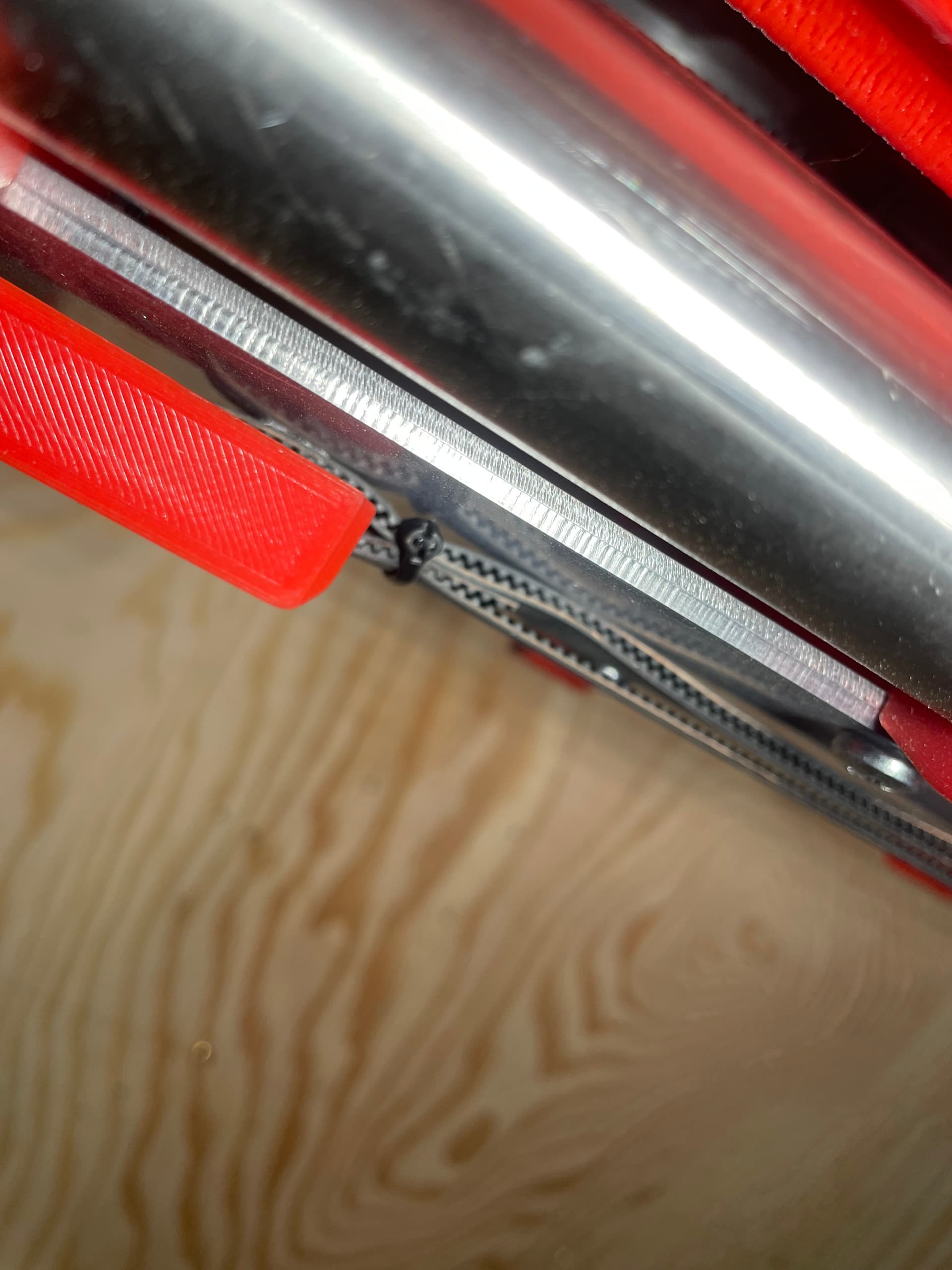
Issue #4: This iteration of the LR3 is a smaller, temporary stage on the way to a much wider build. Because I am a cheap bastard at heart, I decided to not cut the X belt to length, so that I could use it later for the larger build. I routed the slack along the front strut, but this meant that there wasn’t anything other than friction holding the belt from slipping. Well, the forces from cutting eventually overcame the friction forces, and the belt slipped in the middle of the cut. Fortunately I caught this fairly quickly (another reason to never leave the machine unattended), and there was no damage to the material. I had to reposition the belt a few times until the end-mill fit nicely into a marker hole that I had previously drilled into the spoil board at 0,0,0. Then I used a small tie wrap to secure the belt and the slack together, hopefully preventing any future slippage.
Issue #5: I noticed after pausing when the loose cut-out piece moved and jammed (post #137) that the holes nearest Home were nicely through cut, but the holes farthest away from Home on the X axis were not cut all the way through. I did a measurement of the gantry at each end with a telescoping gauge, and found that I somehow forgot to adjust the Z end-stops prior to now, and they were out by at least a couple of mm. I adjusted them and all of the subsequent cuts were pretty much even and all the way through.
So combined with the failure to secure the cut out pieces as mentioned in Post #137, that is pretty much an even half dozen issues overcome while cutting the 3/8" aluminum YZ Plates.
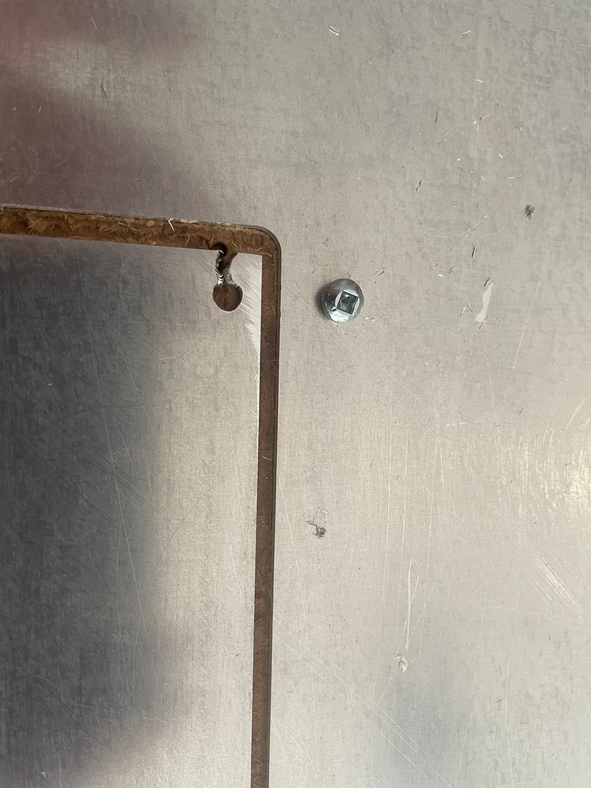
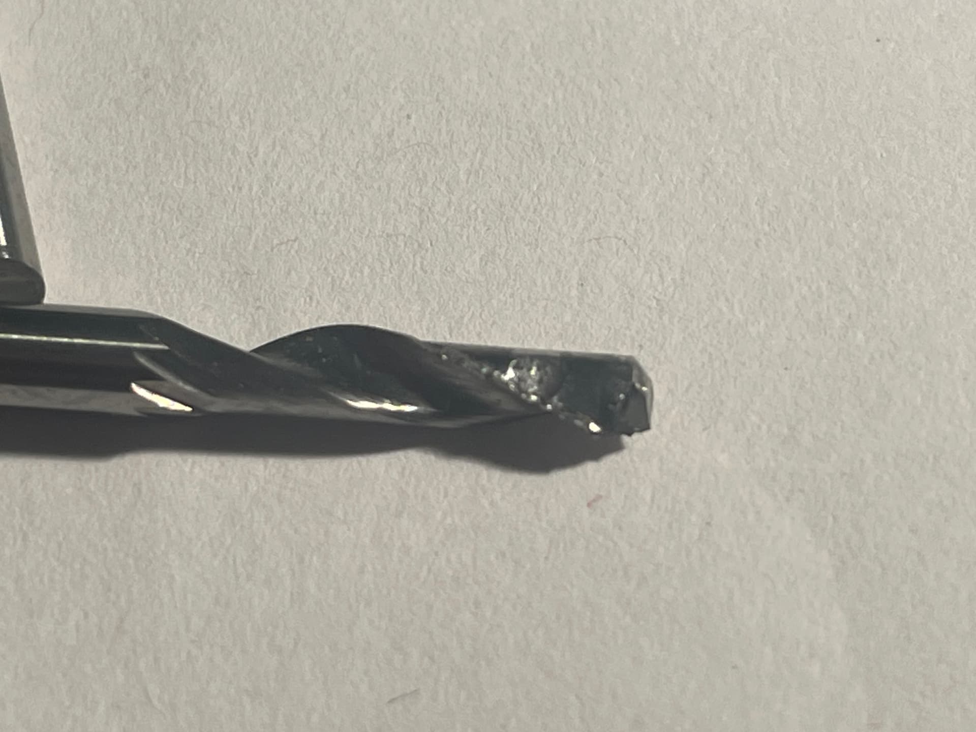
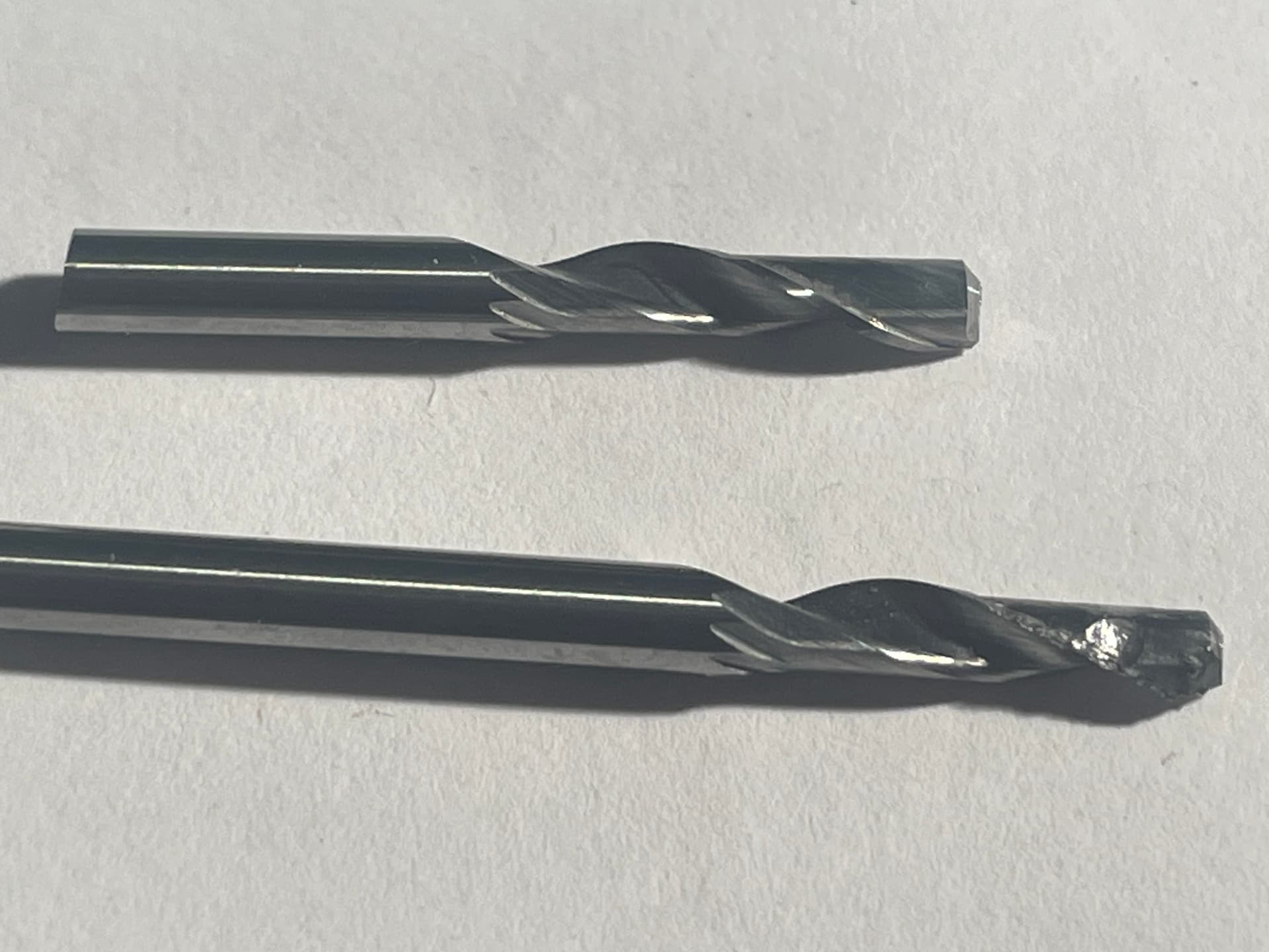
I’m getting quite a collection of broken and damaged end mills along the way.
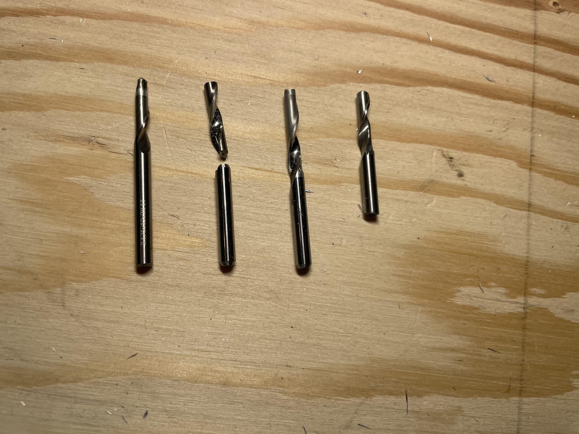
From left to right:
#1: Aluminum welded onto end of mill when insufficient clearance plane caused the mill to jam into 2mm plate during cutting of strut (Post #126)
#2: Mill broke when it jammed into material due to insufficient core clearance from hold down screw (this post).
#3: Dull and some minor aluminum welding after mill jammed into material after failing to secure cut out pieces (Post # 137)
#4: Mill broke when it struck a small rock chip embedded in the hardboard spoil board from the factory (Post 129, although I didn’t discover the cause until later, so it is not mentioned there).
So next up is to disassemble the current small LR3, and assemble the full size version. The more observant of you may have noticed the lack of a hole for the Y motor on the YZ Plates. That is because I intend to use @Fabien’s side mounted belt design (LR3 Side-mounted Y belt - #22 by Fabien).
That will throw a bit of complexity into the cutting of the rails and struts, as the width between the XZ plates now depends on placement of the side mounted belts, the thickness of the YZ Plate and the thickness of the XZ Plate. The LR3 Calculator isn’t able to factor in all of those variables, so I will probably have to partially assemble everything, then do some careful measurements while the parts are temporarily held in place.
Whew - seems like time for a beer break!
6 Likes