Solid milestone right there! Aluminum always teaches me something…
2 Likes
Very solid progress!
3 Likes
Great work! Point impressive steps to overcoming obstacles.
1 Like
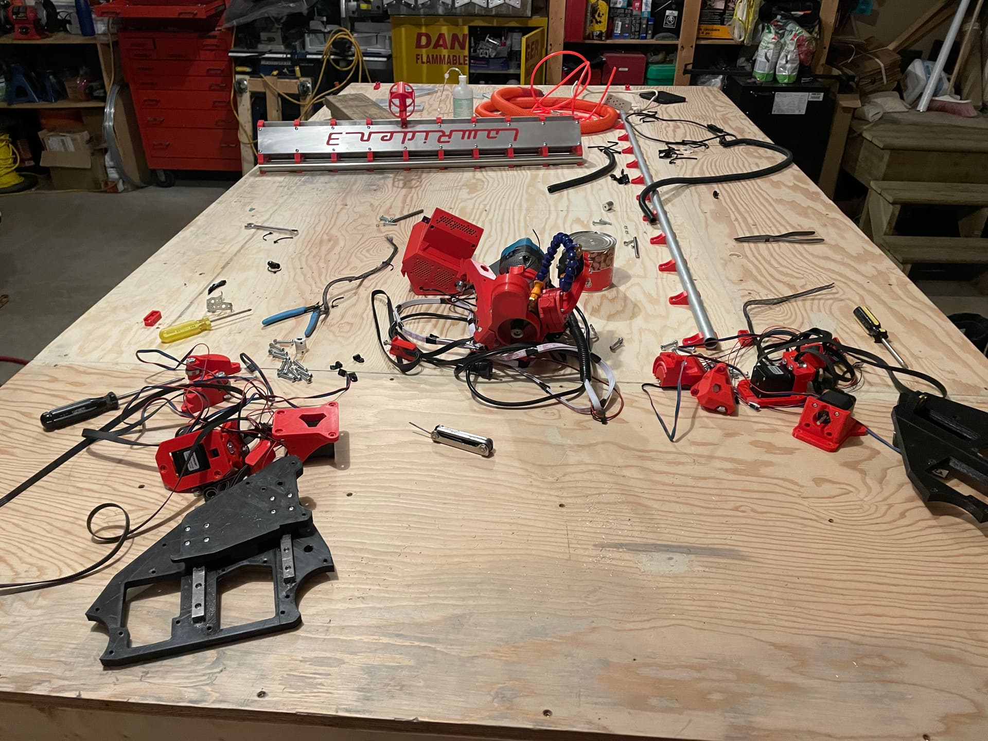
Well it is with much fondness and some slight nostalgia that I bid farewell to “Little Red” LR3.

I learned a ton putting this together and making my first cuts in hardboard and then aluminum. But it has served its purpose, and now it is time to move on to the next phase of the project.
“Little Red” is being dismantled to make way for “Big Red”. This will be a full size (63" x “120” table, approx 52" x 105" cutting area) build, with a few modifications from standard build:
- Side mounted belts (both sides) to increase cutting area, reduce possibility of snagging belts, and allow easier loading of material onto table
- Swapping of X & Y axis to make the table “landscape” rather than “portrait” (more details in an upcoming post)
Disassembly was fast, less than an hour to remove all of the motors and bearings from the YZ Plates (way faster than assembly, but that seems to be the way of things).
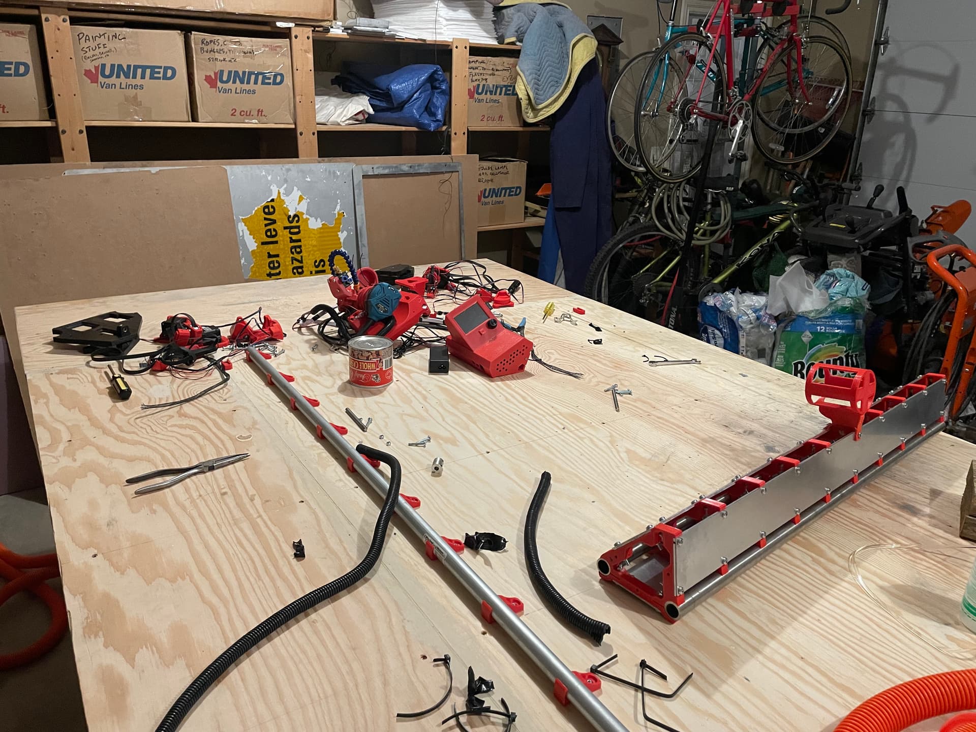
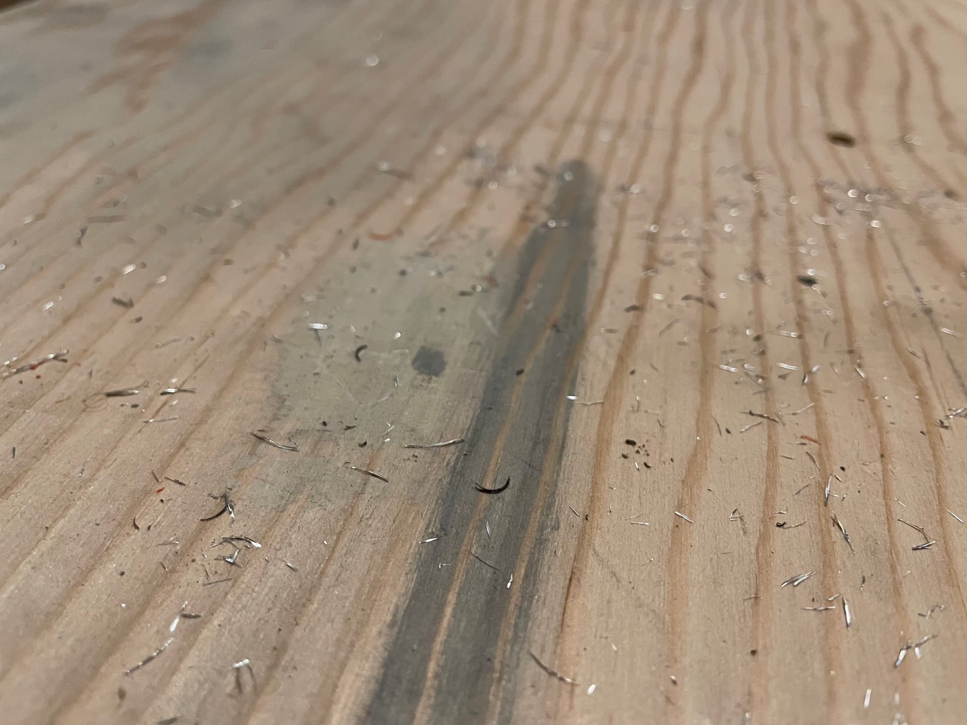
In the last post I mentioned that aluminum chips went EVERYWHERE! Well I found a bunch more during disassembly…
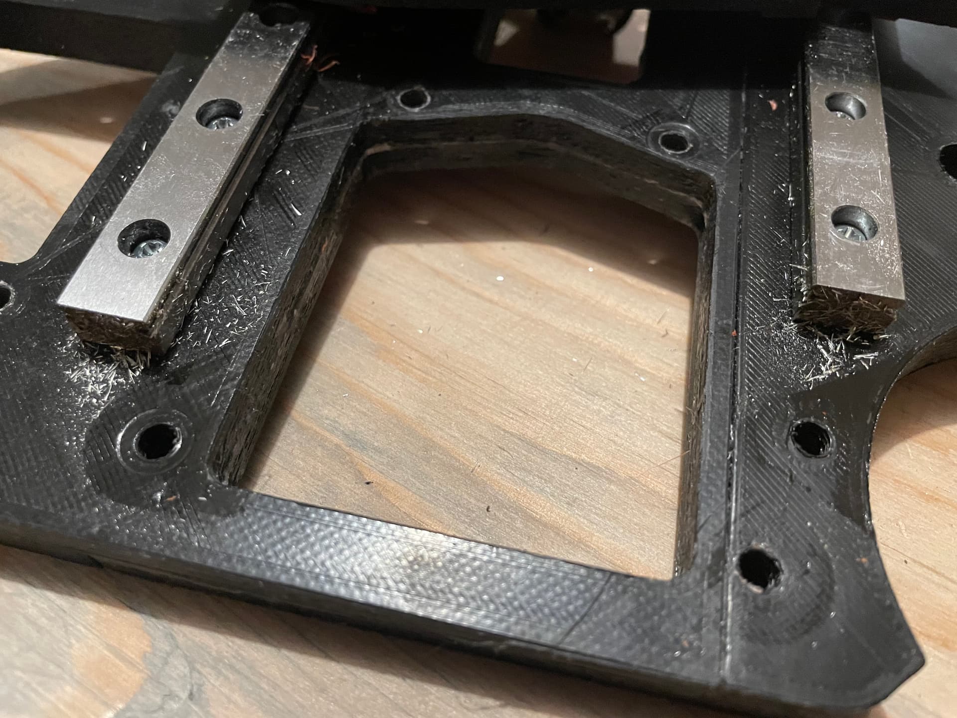
Tomorrow will be the start of re-assembly, starting with moving the linear rails from the printed XZ and YZ plates and onto the new aluminum plates. I’ll have to take a bit of time to work on wire/cable management as I put everything together, still haven’t decided whether to us shrink tubing on everything, or continue to use the mesh loom that I used for Little Red.
6 Likes
Congrats! Thanks for keeping us posted!
1 Like
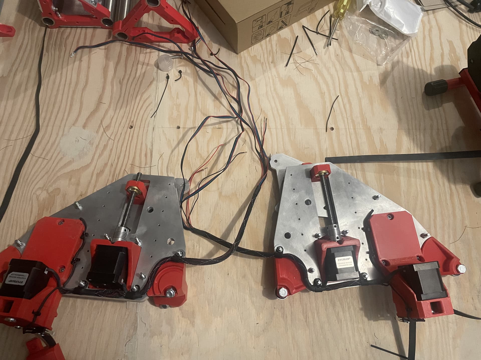
Some good progress today. Rebuilt both sides XZ and YZ Plates Assembly. Used threadlocker on all of the 3mm screws holding the linear rail to the plates, and on the Z axis grub screws (X axis and Y axis sprockets didn’t get disturbed, so didn’t re-do those ones).
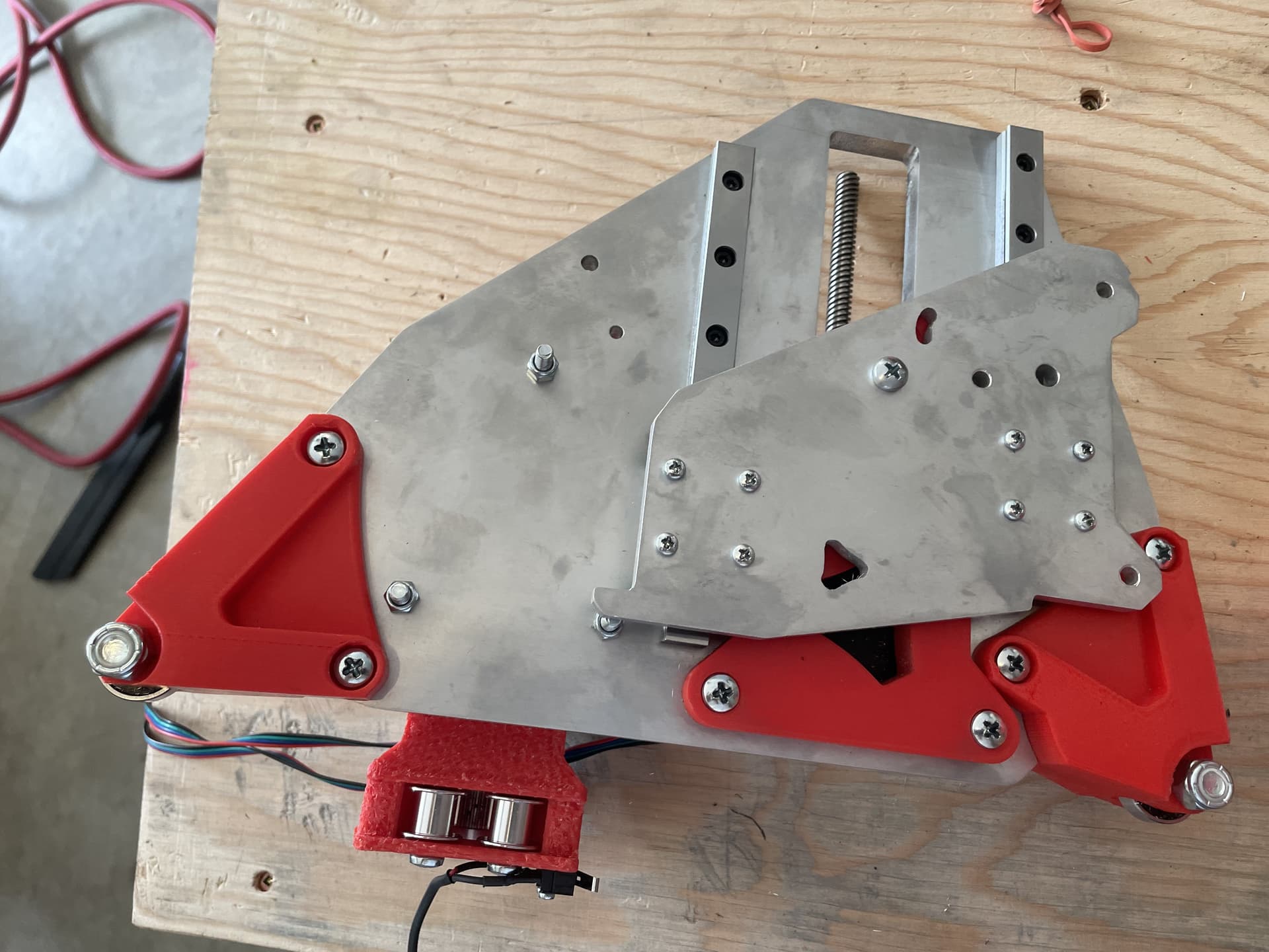
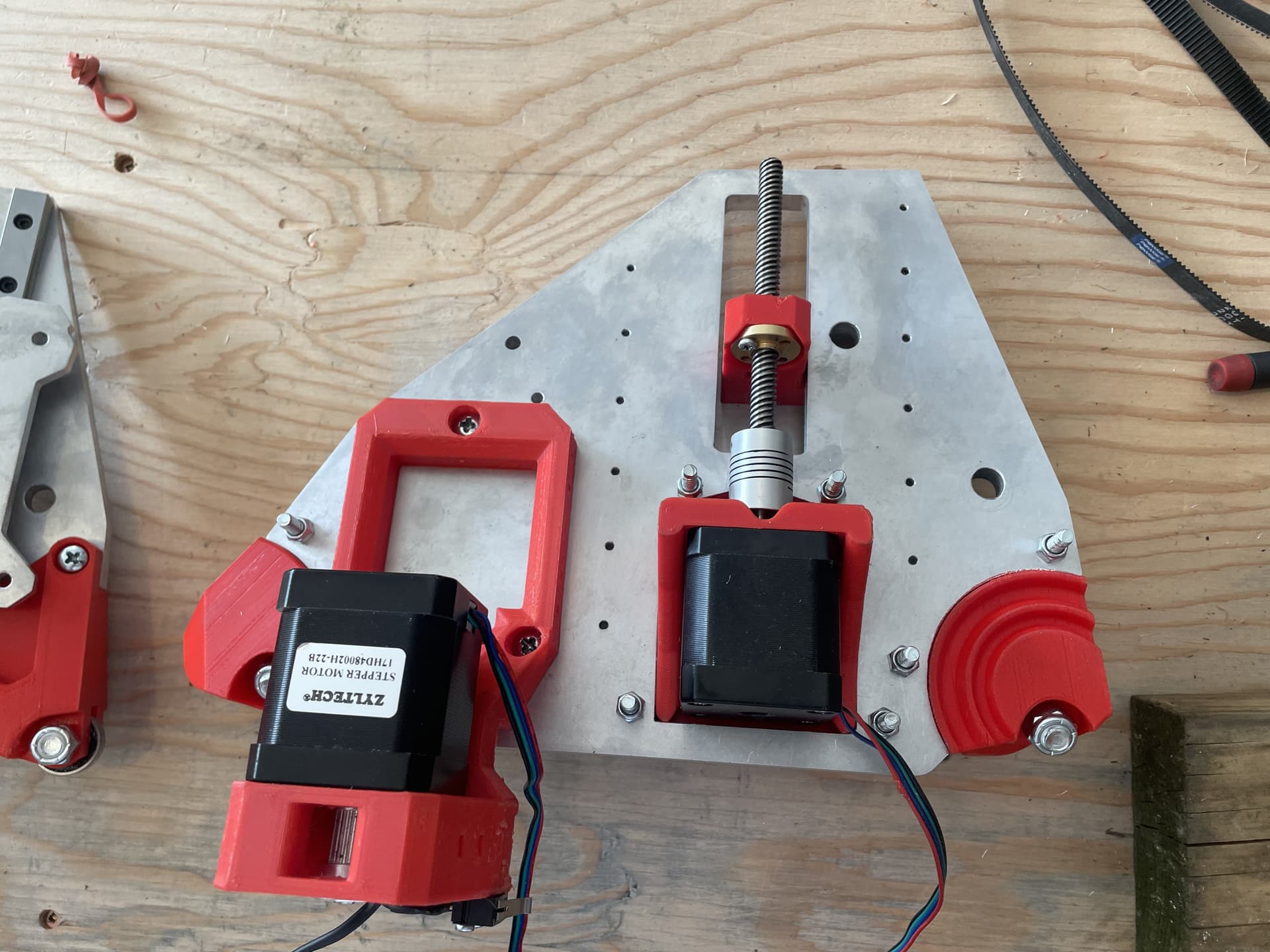
Everything went together really smoothly, except one of the Z motor mounts wouldn’t fit into the hole in the YZ Plate. I had to use a file to widen the hole by about 0.5mm. Not sure why, the other one fit perfectly, but it might have something to do with the restart after a failed cut on that hole…
I also replaced the short Y rail with the full size (10’) one. Still need to screw it to the table, but am waiting until I get the side mounted belt holders mounted to determine the exact distance from the table edge to place the rail.

3 Likes
Ran into a bit of a hiccup on the rebuild, which has put me on a bit of a diversion, and has delayed things a bit…
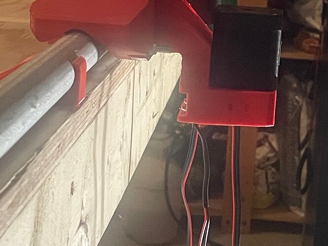
As mentioned several times above, my plan has been to use @Fabien’s truly cool (somewhat parametric) side mounted belt Y motor holder. It is designed for use on the non-rail side, and it worked great there…
However on the rail side, it sticks out a bit too much for my plans, which was to put the rail right at the edge of the table.
I looked into @Rob_W 's remix version, which sits a bit closer, but still was too far away for my plans.
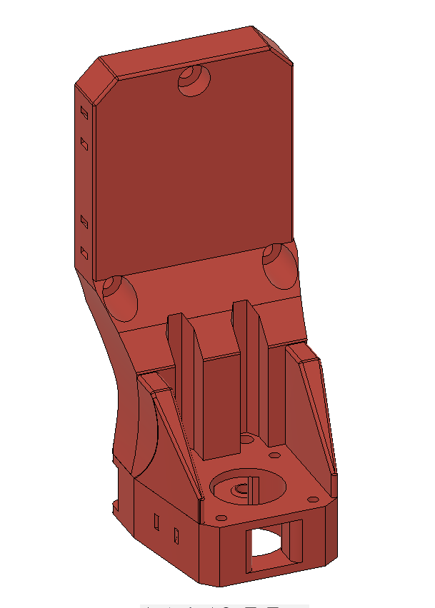
So I ended up doing my own remix of Rob’s remix, and made a version that allows for the Y rail to be right at the edge of the table:
I must admit that when I considered doing a remix with F360, I didn’t have a clue how to proceed or where to begin. However @Rob_W very patiently and helpfully gave me a few tips and pointers, and got me started on the journey. There is no way that I could have accomplished this without his help, so THANK YOU!!! Also kudos and many thanks to @Fabien for his valuable contributions to the discussion, and for creating the original design!
(More details about the process and the issues involved starting here…)
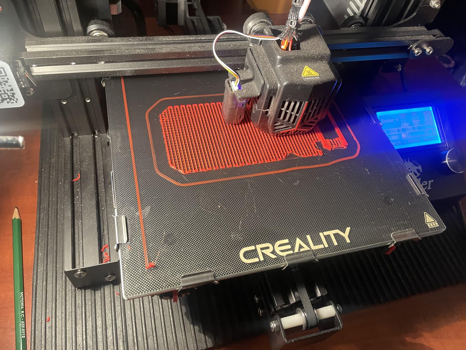
So now I just need to dust off the Ender 3, print out the new motor holder, then it is back on track!
3 Likes
Cool! Thanks for the updates!
1 Like
Looks great!
1 Like
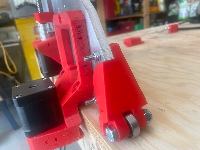
Well this has been a definite learning experience!
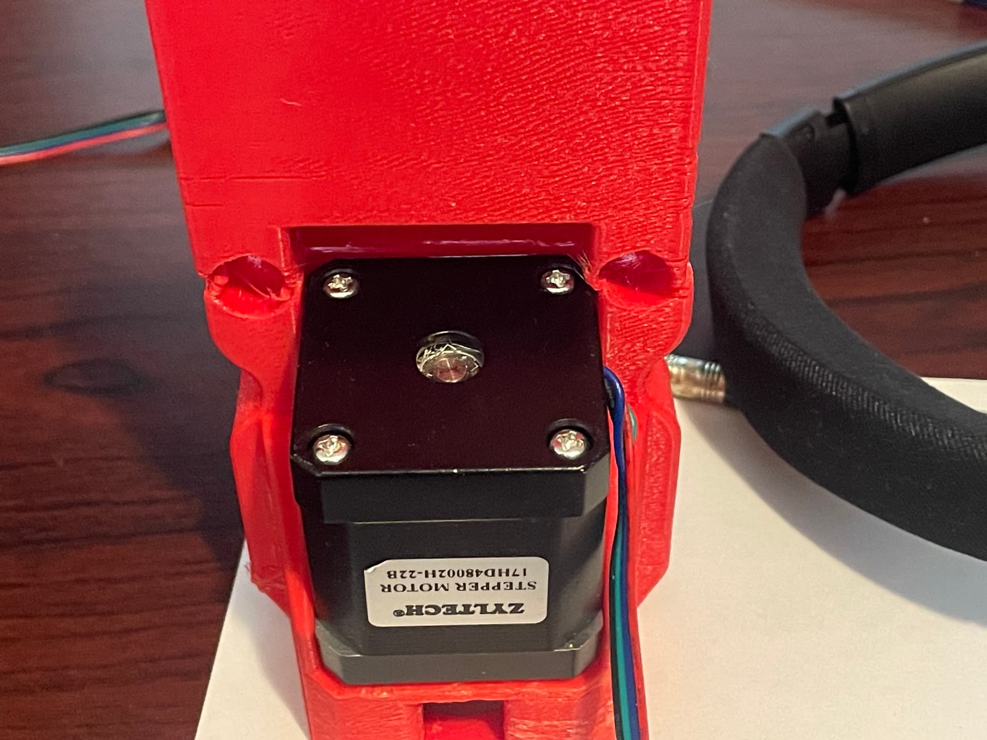
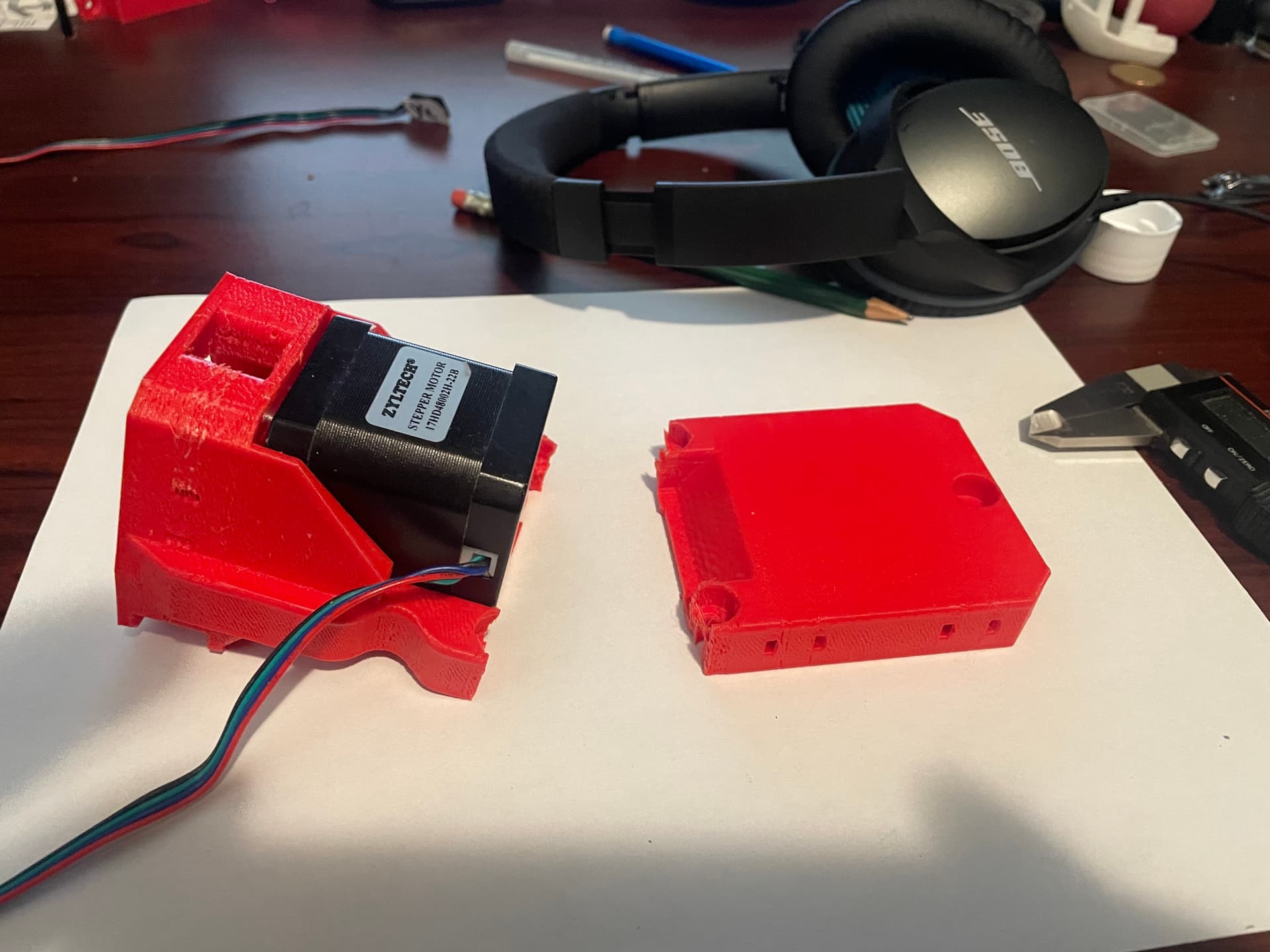
I printed my (first draft) modified side mounted Y motor mount, and ran into a bit of a problem…
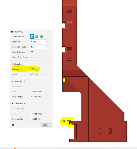
I had moved the motor as close to the Y plate as I could, and left about 3mm behind it to have some backing between the motor and the Y Plate. This meant that I had to leave an angled section to be able to fit the pulley end of the motor into the hole, then straighten the motor and push it all the way into the hole. It also meant that the area surrounding the lower Y Plate mounting holes had very little supporting material on either side.
Additionally, I printed it in a vertical (standing straight up) orientation, as I was concerned about the supports leaving a rough surface on the interface between the Y Plate and the mount.
In hindsight I should have been able to foresee the consequences:
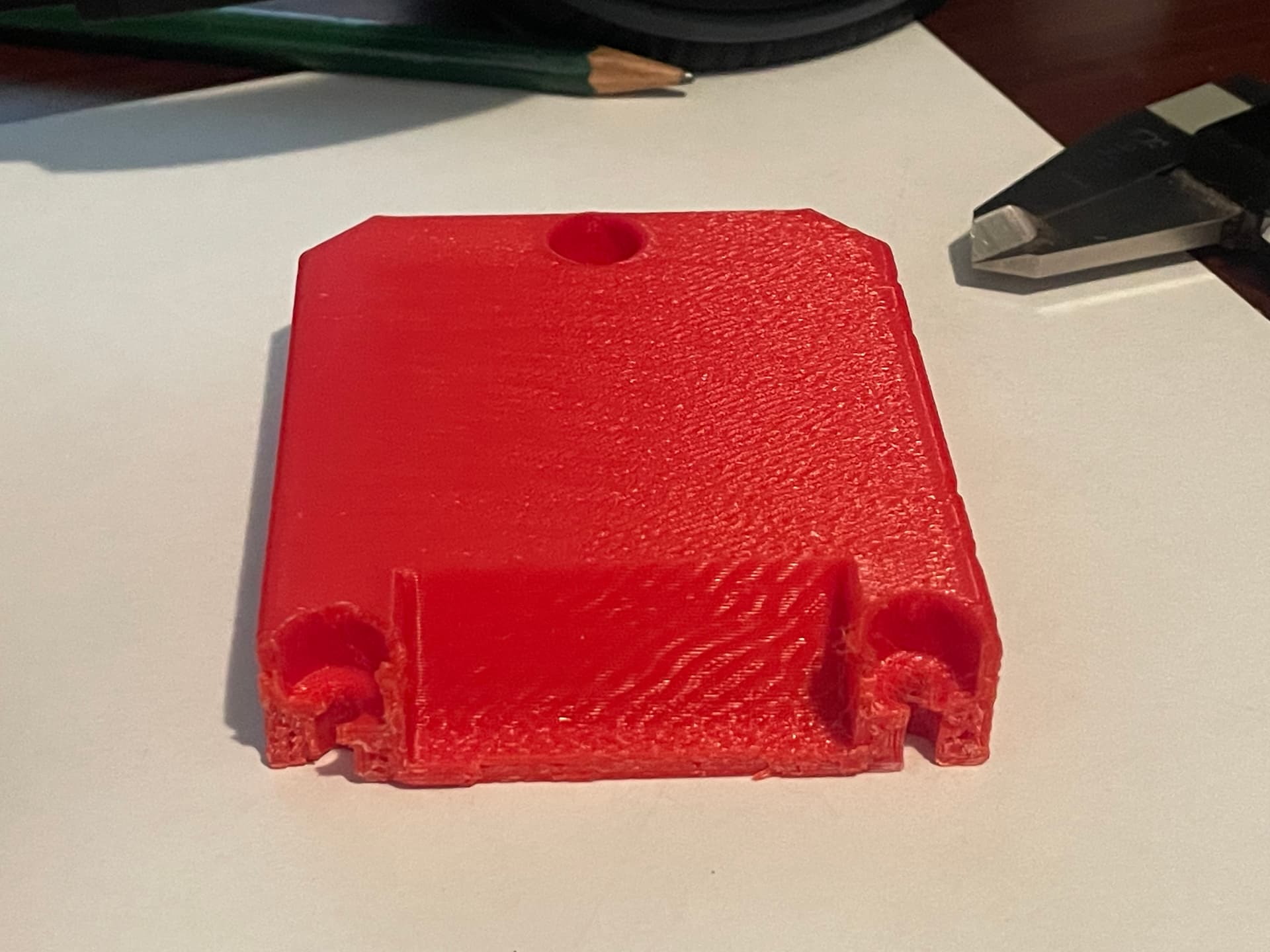
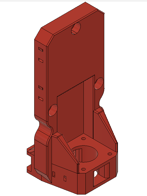
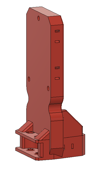
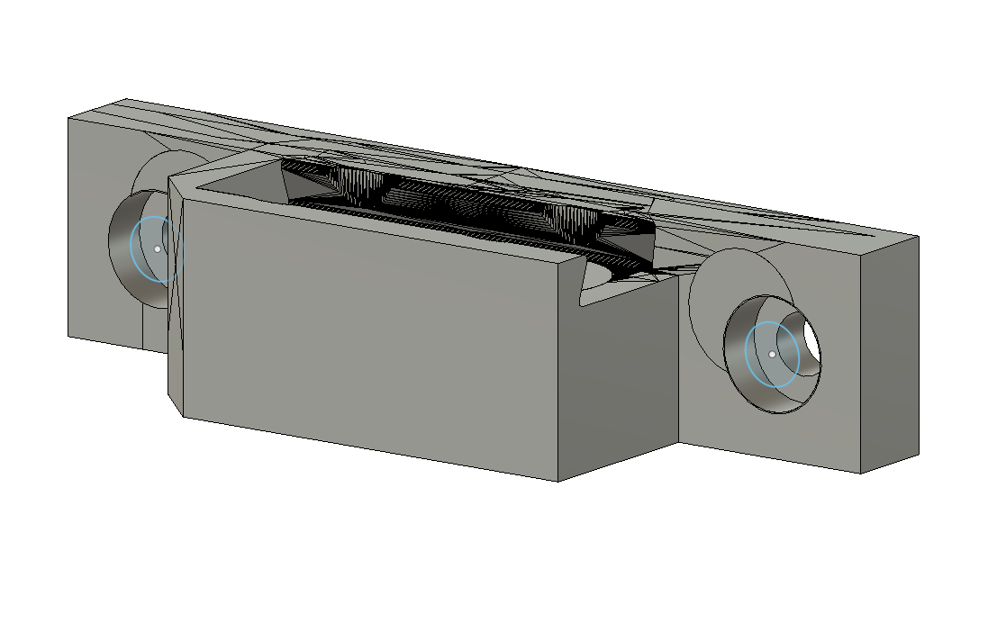
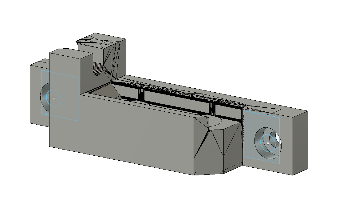
So I went back to the drafting board (screen) and came up with a second version that moves the motor further away from the Y Plate, and increases the backing thickness to full depth from top to bottom.
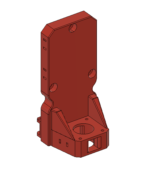
I changed the print orientation so that the layers are parallel to the Y Plate, which should hopefully provide some additional strength. Hopefully the support residue won’t be too messy
As I was putting the finishing touches on the design, I realized that my earlier print of the non-rail side was about 10mm shorter than the rail side, and I wanted the belt a bit lower on the side of the table, so I pulled out @Fabien’s parametric design file and increased the length. Not being able to leave well enough alone, I modified that side’s design as well. adding some additional reinforcement.
Hopefully I’ll be able to reassemble everything this weekend. I’ll post photos when I do.
5 Likes
We are all still learning. Setbacks like these are what builds us. Looks sweet though, hoping to see it on your machine soon!
2 Likes
All part of the prototype-design-print-test-repeat cycle. Happens to the best of us. Carry on! Fine work.
1 Like
Yup! Every time I print something, I see a way that I can “improve” on it. Somebody somewhere said that perfection is the enemy of good, so I usually draw the line at “it works, and it doeen’t look horrible”.
2 Likes
And hopefully I will be until the day I die!
I just received my one year “Anniversary Badge” on V1 Forum, and it is a good reminder that a year ago I hadn’t even heard of 3D printing, gcode, Fusion 360, EstlCAM, feeds & speeds, etc, and while I was familiar with the terms CNC, CAD & CAM, I really didn’t have a clue what it meant or how it worked.
Fast forward a year, and here I am cutting 3/8" aluminum with my own CNC machine, remixing and designing parts using F360, and printing those parts on my own 3D printer. Not bad for a rookie noob (IMO)!
8 Likes
It is amazing i started on this road because my dad said there must be a better way to drill all the holes in these cribbage boards and 7 years later im still shaving minutes off the time ![]()
![]()
5 Likes
So it seems that once I get rolling on a path, I tend to continue rolling down that same path for a while.
In that spirit, I remixed a couple more items.
I found that @Fabien’s side mount front bases and tensioner bases had the belt a little too close to the edge of the table for my liking, and the screw holes were tapered for flat head (countersunk) screws, while I am using pan head screws. I also found that the screw location on the front bases was interfering with sliding out the belt holder (it was okay if using flat head screws, but the pan heads were sitting proud and preventing the holder from sliding in or out).
Also, a couple of months ago I was reading a thread where one builder’s rails were a bit longer than the strut, so they were touching the XZ plates and causing the whole build to be a bit out of alignment.
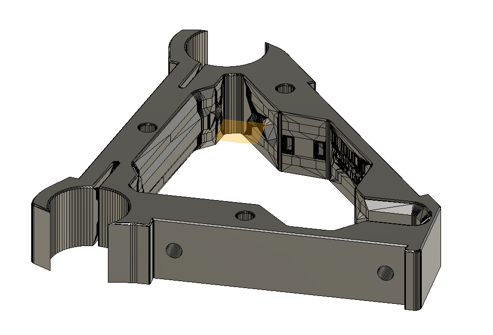
Because I have seen this happen a few times, I pondered in that thread about making the end braces a few mm wider than the other braces, to provide some extra space to prevent the rails from extending past, and to provide a bit more rigidity and a bit more clamping force.
So I went ahead and remixed the standard brace to be a bit wider, for use on the ends. (same printing instructions as normal end braces - mirrored and thicker infill)
Just waiting for the last item to finish printing and then re-assembly can proceed.
4 Likes
My work space exploded!
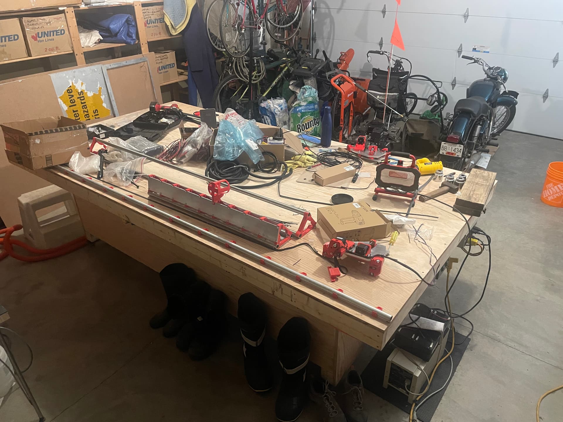
I got the wiring/cable management mostly done, and the belts threaded through the Y motors
With the thicker end braces, I need to get longer M5 machine screws to match. So another delay while I head to the hardware store.
3 Likes
late reply i know… but just to add some info for anyone running an ender 3 series printer on marlin that finds this on a google search like i did… “mriscoc professional firmware” is the droid you are looking for. its a bit complicated at first (or might appear that way if you arent used to github) but there is a lot more control in that version of marlin for the ender printers. if you want to go really far with it you can even run a dumbed down version of input shaping if you want … but even just running mrisoc’s firmware enables s-curve accelleration and if you pick the right version you get model predictive temp control . also pva (elmers purple cheap) glue stick on the glass and insulate the underside of your heated bed to eliminate uneven heating. and if you feel spendy a pei flex plate clipped to the glass don’t bother with the magnet because the glass is still useful for other materials. no more adhesion issues. the warping will never go away entirely, and stiff springs for tramming are a must… the bed tramming wizard in mriscoc firmware i think is better than stock creality marlin but i haven’t tried crealities newer versions maybe it already incorporates it. in case anyone else reads this and doesn’t already know tram and mesh your bed when its heated to printing temp. all this knowledge might be somewhat obsolete with newer enclosed klipper machines, but for bootstrapping your way up… as ryan is helping everyone do… you can still get an ender 3 v2 for not much more than a hundred bucks… lol. i started nursing right when paper charts were phased out to EHR so i had to learn the old way during the first 6 months, then computer charting after. doing marlin and ender 3 the way you and i did may be “the old way” but knowing it still gives a big advantage later like you say.
anyway i’m guessing you already know most of what i said… but just adding it for others… and google too so it finds this thread with lots of useful things bc i wished i’d known those specific things first when i was at the stage of learning you were at in this post. also ellis’s tuning guide… anytime i asked on reddit “go see ellis’s 3d print tuning guide”
finally congratulations your build looks very rad. shooting for something like what you and a few others i’ve seen on here … peter h others. that i can use as a router and drag knife cutter for fabric too.
2 Likes
Well it’s been a frustrating few weeks.
I got the new build mostly assembled, and found that the wiring for the end stop switches was too short to reach the controller box. I didn’t have all of the crimp terminals and tool to make plug in extension cords, so I cut the existing cables and soldered some wire in the middle. Unfortunately I didn’t notice that one of the spools of wire that I used was #24 solid, rather than stranded, and a couple of the solder joints kept failing. This resulted in intermittent “Triggered” states on a couple of the end stops. I ended up cutting out the original splices and inserting sections of twisted pair #24 wire, and things started looking up - for a while…
The next thing I found was that the changes to the wiring resulted in intermittent “pull up resistor” issues, especially with one end stop in particular. In some cases, everything would work as expected for initial homing, but after travelling to the far end of the table and back, the end stop would try to continue past the end stop block, even though the LED would assert. It was frustrating, because I couldn’t do the M119 command as it was grinding through the end stop block, and when I was able to do an M119 command after power cycling, it would mostly show as triggered. I ended up soldering on some 1.5 kOhm resistors to the underside of the board, and that seemed to fix the problem. Everything was going great until…
As I was sliding the controller box cover on for what I had hoped was the final time, I felt a bit of resistance, and then the LCD screen went black. When I removed the cover, I discovered that the 3.3V LED was not lit, and there was a dead short between 3.3VCC and GND. I rechecked the resistors that I soldered on, and there weren’t any obvious solder bridges, and I inspected the cabling, and even removed all of the connectors, and there was still a short circuit. I tried to remove F3 fuse from the board to isloate the section where the short was, but my SMT soldering skills weren’t up to the task, and I ended up desoldering a nearby resistor, and pretty much making a mess of the board.
After debating with myself whether to stick with the SKR board or go with a Jackpot, I decided to stick with what I knew, and ordered a replacement from the Biqu website, as there was free shipping to Canada. It arrived in the mail about 10 days later, and I installed it yesterday, thinking that I was finally on the home stretch. Until…
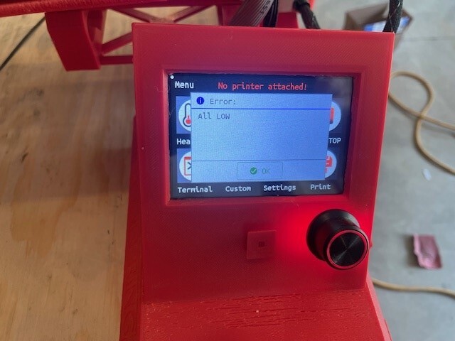
I pulled off all of the plastic JST connectors so that the Dupont cabling connectors would fit, removed all of the excess jumpers, swapped the drivers from the old board, wired everything up, flashed the firmware, and powered it up. Then I got the very disappointing “ERROR: ALL LOW” warning message on my screen.
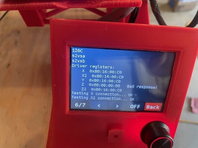
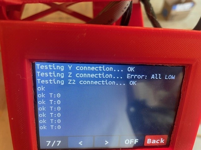
I swapped drivers, and then swapped motor wiring between Z and Z2, and in each case it stays with the port. The weird thing about the message is that it says that Z has the error, but it is actually Z2 that isn’t moving.
So I have opened a ticket with Biqu support. I’m hoping that this gets resolved without any drama or added cost. And I’m really hoping that this is the last in a string of unexpected problems .
2 Likes
AAARRRGGGHHH!
Just to add to the misery, when I was testing the motion on all of the axis while troubleshooting the failed port, I discovered that one of the TMC2209 drivers has gone wonky, and now will only move in one direction, regardless of whether I send a + or - movement command. Swapped the driver between a few different ports, and it definitely follows the driver.
Not sure what I did to cause this. During the troubleshooting of the failed port, I cut off (actually bent them back and forth until they broke) the previously bent pins on the bottom of each driver. That and removing/replacing the drivers once or twice. But I was pretty gentle with them, or so I thought.
So now I have one port that doesn’t work, and one failed driver. Still waiting to hear back from Biqu about the former, will probably have to buy another driver for the latter.
1 Like