EstlCAM 12 Parameter Sets - I Am Confused

I just switched from EstlCAM v11 to v12, and I am seriously struggling with setting up the parameter sets in the tool list.

I did try to follow the German language video along with the subtitles from @RegPye, but while I THINK that I grasp the basic concept, the details are eluding me.

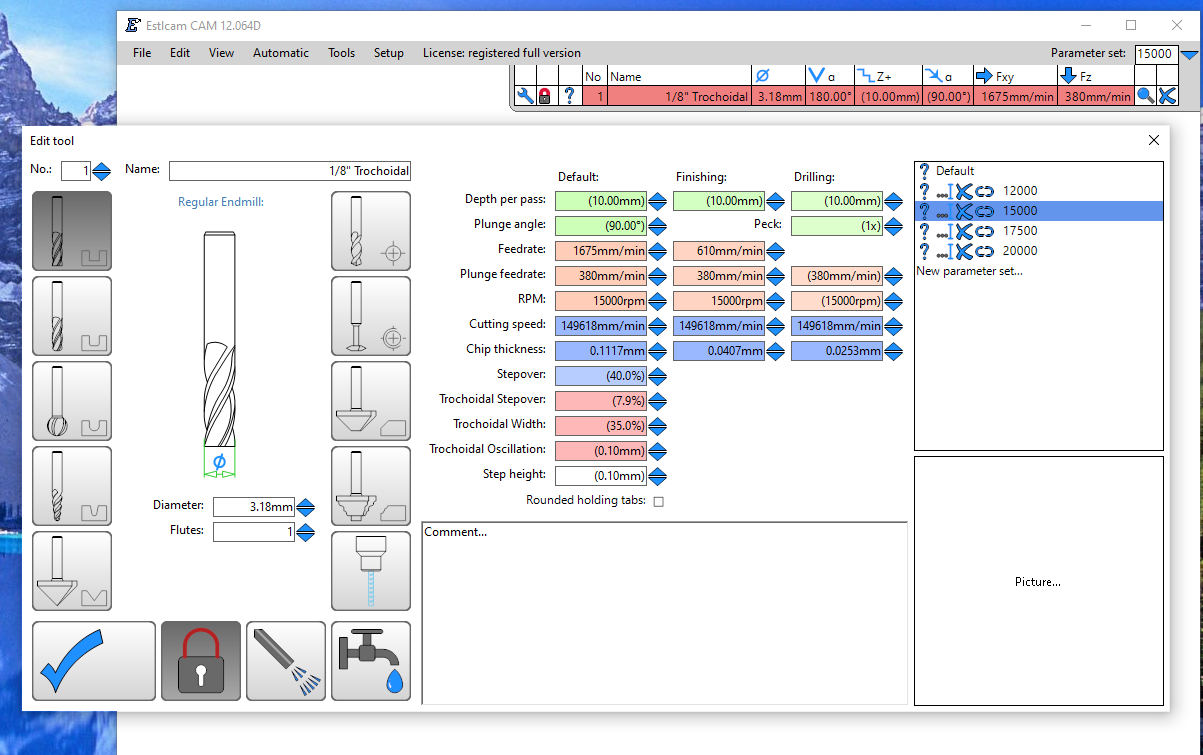
Please tell me if I am getting this wrong. I am using a 1/8" (3.175mm) single flute end mill, and I created a different tool for various RPMs (12000, 15,000, 17500, 20,000). I then created unique parameter sets for each tool (speed) for a variety of materials and milling types (Aluminum Trochoidal, Aluminum Non-Trochoidal, Plywood, etc.). Using G-Wizard to determine appropriate feed rates, I then filled in the various parameters for each parameter set in each tool (RPM).

So far, so good, but I have a couple of things that are confusing me…

The video and hover-over help message says that I can “indicate the tools suitability for this parameter set”

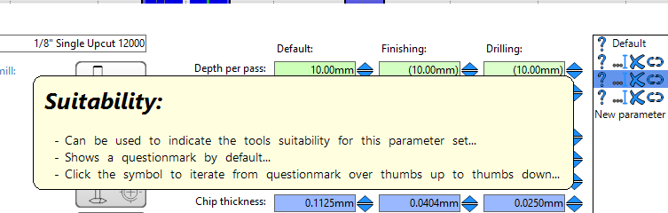
I don’t know what that means. Basically I set up the tool’s parameters so that it was suitable for the named material. So what exactly is the “thumbs up” or “thumbs down” trying to indicate? I’m obviously missing something here…

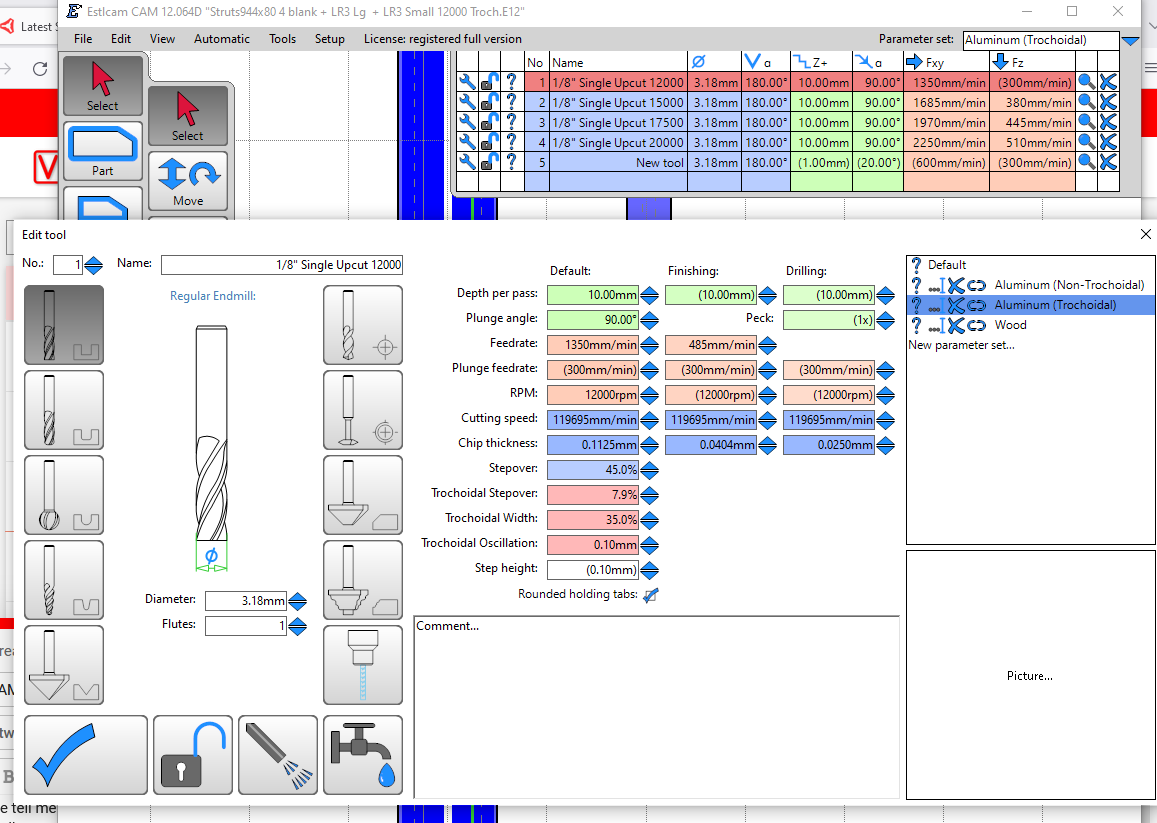
The next thing that is tripping me up is that I can’t seem to apply one parameter set from a given tool to some parts of the project, and another parameter set to a different part of the project. For example, I am cutting some aluminum struts, and I have applied Aluminum Trochoidal parameter set to all of the screw holes and parts, but the trochoidal milling is too wide for some finer text holes in one of the struts. So I chose Aluminum Non-Trochoidal parameter set using the same tool, but all of the toolpaths previously assigned to Trochoidal immediately change to non-trochoidal.

Another item I noticed is that in v11, you could select the "magnifying glass? icon, and all of the toolpaths for that tool would be highlighted in red. With V12, the toolpaths seem to follow the tool itself, rather than the parameter set within the tool. In other words, if you have set everything up to use one parameter set, then click on the magnifying glass icon with a different parameter set selected, then everything will change to that new parameter set (rather than only identifying which toolpaths use the selected parameter set)

Do I need to create a completely different tool of I want to use different parameters for the same project?

I think this is because parameter sets are made to go across all tools, so you can say, for instance, that your 1-1/2" Surfacing bit really shouldn’t be used with the Aluminum parameter set, even though it shows up for it.

I think this is still defeating the purpose of parameter sets. Each tool should be the definition of the physical tool, and the parameters change based on the parameter set.

First, the “Default” parameter set should be filled out with the most commonly used settings, so you don’t have to override all of them at each parameter set

This to me is the only drawback I have found so far, and I planned to make a write-up about it to ask @christian-knuell about it. I think Parameter Sets are awesome, but they would be much, much more powerful if I could override the parameter set at the individual toolpath settings window.

I had a few places when cutting my printer plates that I didn’t want to use trochoidal, but my only option was to break it up into different cut files…

Once was because I was trying to get around the drill pecking bug, but it could also because you have a shallower cut to make in one area, etc. Plenty of reasons I can think of to be able to override on the toolpath.

As far as I can tell, the selected parameter set on the tool list applies to all toolpaths.

2 Likes

OK, I sort of get what you are saying, but I plan to use the same tool (1/8" single flute upcut) for a bunch of different uses (trochoidal aluminum, non-trochoidal aluminum, plywood, MDF, etc), and in each use I wanted to have the ability to use a variety of different speeds to test out what the LR3 can handle.

I think with the limitation of not being able to assign different parameter sets to the same project, I will try setting up a series of “tools” using the same mill, but for different applications (1/8" single upcut Aluminum Trochoidal, 1/8" single upcut Aluminum Non-Trochoidal, 1/8" single upcut Plywood, 1/8" single upcut MDF, etc.), and then create a series of parameter sets within each tool for the different speed settings that I want to try out (12000, 15000, 17500, 20000, etc.). That way I can create a series of projects (and gcode files), each using different speeds (and feeds), and each using Trochoidal for the majority of the cuts and non-trochoidal (with a tool change in software, but not on the LR3) where needed.

Another question - when you select the finishing tool in the Properties Menu, how do you specify which of the many possible parameter sets that you want to use? Presumably if you are using the same tool, it will use the same parameter set as the roughing (or will it??), but what if the finishing tool is different than the roughing tool? If you select a different parameter set for the finishing tool, will it affect the already specified roughing parameters?

In that case, you really should have different parameter sets for the different speeds.

The way I look at Parameter Sets, is that the purpose of it was to stop having to create different tools in order to alter a parameter for cutting with it.

Unfortunately, due to the inability to override the parameter set on the toolpath currently, you do still have to resort to that. My comment was more so to point out that you “shouldn’t have to” to do that, but currently, you do.

You can’t, as far as I can tell. Whatever parameter set is selected on your tool list, is the parameter set that applies to all tool paths for all tools.

I really think what we are missing to make Parameter sets more useful is this

The ability to override them per toolpath.

If your parameter sets are set up correctly you shouldn’t need to specify them differently per operation (chamfering vs pocketing vs finishing) within the toolpath.

I know @christian-knuell reads the forums sometimes, but I don’t know what the proper way to ask about this is, so I’m hoping he reads this thread and understands the current limitations with only selecting a single Parameter Set for an entire program

1 Like

a few things i’ve learned lately.

  • Can create new parameter sets by opening an individual tool config/wrench and adding there. Took me a while to find.

  • Suitability icon. I have parameter sets by material. So default=wood, MOP(Mother of pearl), acrylic. These have various properties. so I override the default feed speeds only for needed tools. i.e. MOP is MUCH slower typically. A single flute works great in Acrylic, but MOP supposedly prefers 3 flutes. So for a single flute bit, A thumbs up in Acrylic but a thumbs down in MOP. So I am using the thuimbs up to remind of the approriate tools for the mats and only overriding the speeds and feeds from the defaults for those tools. But I have selected the WRONG tool and used the wrong feeds to cut. That did not go well. So I am hoping the thumbs up will help remind me

  • changing bits, I use the magnifying glass to select my bits. I just recently learned I can change bits for a selected cut if I click the NAME instead. Mind blown. I also just learned that the magnifying glass shows the cuts. Also mind blown. Lots of hidden things to learn.

  • 1 parameter set per JOB. Finishing passes are done by setting a finishing size (i.e. 0.15mm leave to cut small amount to make a final clean pass of that depth) and selecting a tool (can be the same as the original). These finishing passes seem to be set FASTER feed and it knows to use the finishing column speeds in the tool config. However, I need tolerances (a small gap so things fit) for some cuts. Tolerance is added by setting “Finishing” to + or - (i.e. 0.15mm) without selecting any tool. But I wanted both a tolerance and a finishing feed rate for clean edges. I tried to trick the tool by adding another parameter set. hardwood_FINISHING. But I could not find a way to use 2 parameter sets in a job.It looks like whatever parameter set I chose changed it for all jobs. I think your method of duplicating a bit within a parameter set might be a work around but it breaks the otherwise elegant design of this IMO. Instaed, I wish the software would separate finishing passes and tolerance logic so both can be accomplished together. Alrternately, could give a checkbox to use finishing pass speeds for the tolerance. I just checked and tolerance without a tool does not seem to use finishing feedrates.

My $0.02

1 Like

I love this forum for this exact reason!

I learned a few more things about EstlCAM parameter sets and Tool Lists over the last few days as well:

  • You can create and save multiple tool sets,. You can only have one Tool List open at a time. You can choose which of those saved lists will be your Default Tool List.

  • Each Tool List can have unique parameter sets, but you can also have common parameter sets across multiple Tool Lists.

  • When you open EstlCAM, it will load with the Default Tool List.

  • Any changes that you make to the Default Tool List (or to the active Tool List) won’t be saved when you exit the current project (or the program) unless you manually save to the Default (or active )Tool List.

  • The Tool List in use when you save a project will stay with that project. In other words, when you open a previously saved Project, it will load with the Tool List that was in use when the project was last saved, regardless of whether or not you saved the Tool List separately.

But you can Add other lists to the open one as needed. Something I haven’t played with the the saving/adding of individual tools.

Now that I understand the Tool Lists and Parameter Sets a little better, I found a way to accomplish my goal, even if it isn’t exactly how the system was meant to be used.

For background, I am using EstlCAM 12 to create the CAM (gcode) to mill my permanent LR3 struts from 2mm Aluminum. I will be using a 1/8" single flute end mill.

I planned to use Trochoidal Milling for all of the cuts, but I found that the hole size for some smaller text on the front strut prevented the tool from being able to use Trochoidal. Estlcam used the finishing pass for the smaller sections, but it ends up slotting those sections (3.175mm) at a feedrate meant for only 0.35mm, and I worried about possible tool breakage or welding the aluminum to the tool.

I originally tried to use parameter sets for the different feedrate requirements, with one set of parameters for the Trochoidal cuts, and a different set of parameters for the Non-Trochoidal cuts (with suitable feedrates for each set of parameters), but that’s not how Parameter Sets work. As mentioned above, you can only have one parameter set in use per project.

Another objective was to test out different router speeds on the aluminum. I used G-Wizard CNC Calculator from CNC Kitchen to come up with suggested feedrates for Trochoidal and Non-Trochoidal slotting, at a variety of speeds (ranging from 12000 - 20000 RPM). Initially I was going to create a separate tool for each speed setting, but the inability to use both Trochoidal and Non-Trochoidal parameter sets in the same project meant that approach wouldn’t work.

So I kind of reversed the process, and created two tools in the tool list, one for Trochoidal and a second tool (using the same physical end mill) for Non-Trochoidal. I then created a parameter set for each individual speed setting, and saved them to both tools. Each tool has it’s own feedrate setting for the common speeds, and I can assign multiple tools to the project as long as each one is using the same parameter set.

A bonus was that it was super easy to save the individual CNC Programs (gcode files) for each speed. Once the toolpaths were assigned to both tools for the first speed setting, all I had to do was change the parameter set on the top right corner, save the project under a different name (with the speed setting as the variable in the name) and then save the CNC Program using the same name as the newly saved project.

Cutting time ranged from over 4 hours at 12000 RPM to less than 2.5 hours at 20000 RPM. I plan to do an “air cut” at each speed first to see how much shaking and vibration there is at the higher speeds, and whether the LR3 can handle it.

I’ll post the feeds and speeds on my build page in the next few hours, along with the results once I do the air cuts and the actual cuts.

Now you are learning, and teaching at the same time. Well done

Check your drilling setting in the above screenshot.
I got caught on this one not long ago. I ended up doing a very fast deep drilling unexpectedly and stalling my machine, lucky I didn’t break anything.
I reduced my which was set to 7mm down to 0.5mm for the drilling, now it works ok.
Easy trap to get caught into.

Sorry, which setting did you reduce? (DPP, Peck or Feed Rate?)

I just ignored this column, because all of my toolpaths are either Holes or Parts. That leads me to question whether I should have used the Helical Drilling function instead of Holes for the 5mm screw holes in the LR3 slots.

But yes, I can see how leaving those settings untouched could be a trap for future operations. Thanks for the tip!


The Default setting is the same as Finishing and Drilling by default, so be careful to watch what to change before using or you may end up with a broken tool or even machine and most definitely your work piece.
I overlooked it the first time, just doing the same as you, cutting out a part, and then came the time when I needed to use the same size tool that I was using for trochoidal cuts for doing some drilling in the same job. The tool plunged down at high speed and down to the software default which was 7mm - big trap.
I should also go back and change the Drilling Plunge Rate, reducing that down a lot as well.

2 Likes