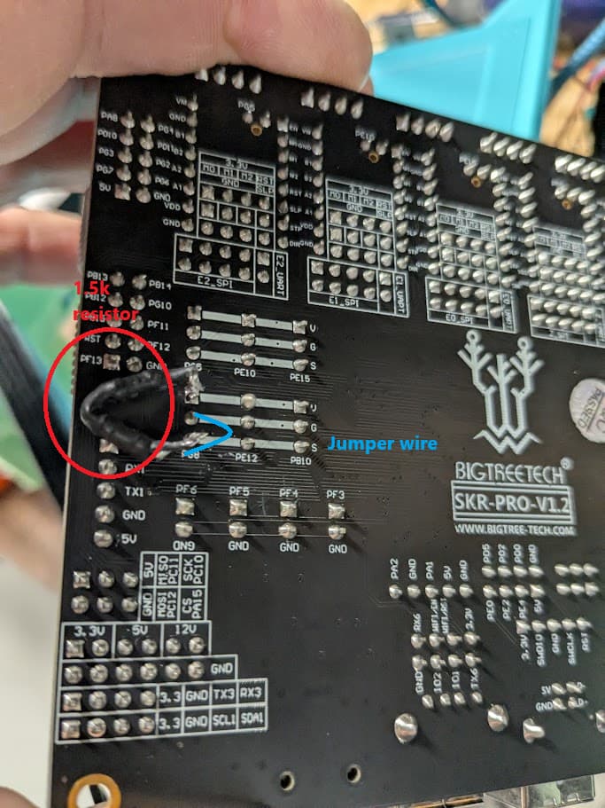
My ongoing saga of Z endstop not triggering on a stock MPCNC continues. I put together a pigtail and that didn’t work, so I ended up soldering the resistor from pin 1 to pin 3 on PG8, which corresponds to the Z endstop plug on an SKR Pro 1.2 build.
I’m still not getting any response when I close the circuit on my Z endstop. I have continuity on the wires for the endstop, I have 1.5k resistance when I test pin to pin, and I’m running freshly flashed stock firmware.
The only thing I can think of is that my 1.5k resistor is two resistors totaling 1.5k, and it doesn’t like that for some reason. Or maybe I’m misinterpreting where pins 1 and 3 are for the endstop plug.
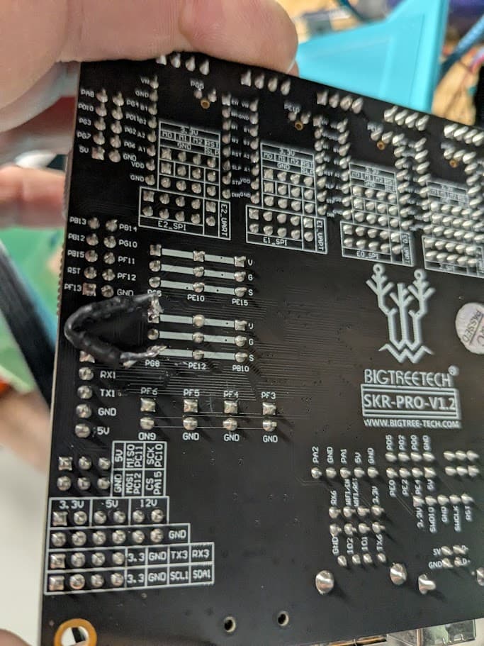
Here’s what my soldering job looks like. Can I get a final sanity check on everything I’ve done before I just give up and order another SKR from the V1 store? It’s not the prettiest soldering job but it is solid and like I said, it tests with 1.5k ohm from pin 1 to pin 3:
2x resistors in series to make 1.5K is no different to a single 1.5k resistor in this case.
Measuring from pin 1 to 3 you should see somewhat less than 1.5K, it should be closer to 1.1k, given that there’s already a 4.7K resistor there. What are the 2 resistors you added to get to 1.5K? I wouldn’t be too concerned here, measuring resistances in-circuit can be a bit difficult as you’re effectively measuring all possible paths through the circuit at that point.
Just to verify for sure, I would take a piece of wire and carefully connect pin 2 and 3 together now. You should see the Z trigger and the LED go out.
Another option would be to measure the voltage on pin 3 relative to pin 2 while the board is actually powered up.
How are you testing the endstops? By trying to home or by using the G-code command that returns the stop conditions?
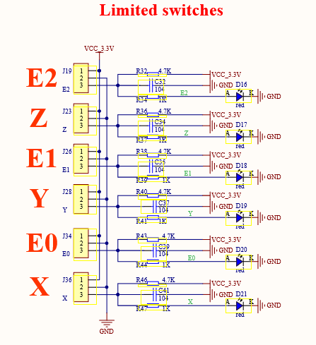
Oh, wtf, apparently I’ve never looked at the SKR Pro schematic that closely.
It actually seems to have the input to the chip measured off the anode of the LED?? Is that what I’m seeing? If so, that is some hot garbage and it’s no wonder there are so many issues with this, holy crap.
Before sending the board back, I would just entirely desolder the LED (or just clip it off with side cutters if you’re feeling particularly feral).
Ewwwww.
I can’t see what the part number on that LED is, but most red LEDs are in the 1.8V to 2.2V nominal range at 20mA forward current.
The STM32 is a VIHmin of around 1.8V ‘by design’ at 3.3V, but that could easily be 1.9-2V with a pin at the higher end of the leakage current range and with high Vcc.
The LEDs might be 2.0V at 20mA but are likely more like 1.8V at 5mA or even lower, so it’s no surprise there are some boards that just flat out do not work.
The actual solution here would either be to remove the LEDs or to lift one of their pins and add a resistor between the pin and the PCB, then fit a 0R in place of the existing series resistor. Jeez.
The board has been in my hands for a few months, so returning it is not an option. It was working normally for a month or two and I had no issues with the endstop, and then it just stopped working. My MPCNC has been dead in the water for about 3ish months if not more.
My tests were done by touching the alligator clip to the flat metal touch plate. The LED never goes on and Z keeps moving down until I kill the power or reset. I tested continuity with a multimeter, same for pin to pin. It totaled just about 1.5k.
With the power on I show 3.2v between pins 2 and 3. When I connect pins 2 and 3, nothing happens and the E2 LED stays on.
This is a bit odd. If the endstop doesn’t trigger when the pins are jumpered, that either means the board is faulty, or the programming is wrong.
Have you done any changes to the firmware? If so, it may be worthwhile to reflash the stock V1E bin file
If everything else is working properly, you could possibly still use the board if you use the 3D printing method of manually lowering the Z and using a “feeler gauge” method
Edit - as this is a MPCNC, and not a lowrider, you should have an extra endstop position available. You could edit the firmware to use the unused port…
I’m out of town without my computer, so cannot do my usual research to post an answer, but I believe there is an additional endstop plug you can use. You would need to make a reassignment in the firmware to use a different endstop plug for Z probing. It is possible the original pin is bad and the issue is not the usual SKR Pro issue.
How are you connecting them? Can you take some close-up photos of the board and those components on both sides?? That absolutely should not be happening.
Also, I wouldn’t rule that out. Doesn’t matter that it took you a few months to find out it doesn’t work. Nobody uses every feature of a product immediately, it’s perfectly reasonable for someone to discover a faulty product weeks, months or even years after purchase.
This is after a fresh flash (or what I believe is a fresh flash) of the stock firmware - I unzipped the SKR Pro dual endstop firmware to my PC, copied firmware.bin to a microSD card, put the card into the SKR, and booted. I didn’t get any indication of failure, and the gantry moves correctly on X/Y/Z. If I’m doing it wrong or using incorrect firmware I’ll happily try the correct one.
Regarding using another port, I took a shot at it some time ago and it didn’t work. Is this the correct method to change the plug from PG8 (the default one as far as I can tell) to PG5 (the unused port above PG8)? A lot of people have said “edit the firmware” but I haven’t really found any info on what exactly to edit, where to edit it, etc.
I’m connecting pins 2 and 3 by taking a regular Arduino style female to female jumper wire and plugging it in to pins 2 and 3 in the PG8 pin. I also tried touching both pins with my multimeter in continuity test mode. Also touching a male to male jumper wire from pin 2 to pin 3 on the back of the board. Other than soldering a wire to the pins I’m not sure if there’s a more comprehensive way to connect them.
The photo below is how it’s set up - the resistor I soldered in the other day, I’m just not in front of it right now to show how I’m touching the jumper wires to the pins.
I bought this from the V1E store and it’s quite literally been 8 months. I’ve soldered the resistor to it. I wouldn’t expect any retailer to replace the board unless it had an extremely generous warranty that doesn’t care if the end-user could have damaged it or futzed with it, and I sure wouldn’t ask a single-person operation to take a loss by doing so. I just want to make sure I’ve troubleshooted correctly before I cough up $50ish for another SKR, preferably one that isn’t affected by the original resistor issue.
They may not be making contact. Perhaps try with a pair of tweezers or something. I recall people saying to pull the plastic shroud off those connectors to make them work better with dupont style housings.
While the board was powered? I definitely wouldn’t do this. Continuity test mode isn’t a short through your multimeter, it applies a voltage to the board and measures the current through. The behaviour won’t be predictable or useful on a powered board.
And if you do that the LED stays lit?
My perspective is that there are only 3 connections to that part of the circuit. The pin, ground and the microcontroller. If you’re confident you’ve connected the pin to the ground and the LED stays lit then either the microcontroller pin is what’s lighting the LED, which is starting to get into ‘very, very unlikely’ territory.
Honestly at this point I wouldn’t touch another SKR with a 10’ pole, personally. Whoever put together that end-stop circuit needs to not be designing mass production electronics. If anything happens to mine I’ll be replacing it with a Jackpot, for sure.
There is no guarantee that a new board won’t have the endstop resistor issue. I purchased one in June 2024 directly from Biqu/BTT that had the issue, so it hasn’t been fixed yet (regardless of what some might tell you).
This is a quite advanced procedure, and I am using the Lowrider firmware, not the MPCNC firmware, so I can’t tell you the step a, step b, step c method. Sorry, but I don’t have the knowledge to say exactly what lines of code need to change.
I suggest that you start a new thread, asking specifically how to change the Z Probe from the current port (Z) to the unused port (E2)
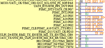
I’m not sure of the “right” way of editing the firmware, but if it was me, I’d likely just swap the pins in the pins file. The file you are looking for is:
Swap all the PG5 values for PG8 and change the PG8 value to a PG5. You would then have to recompile and reflash the board. Ryan provides instructions on how to do this using platformio.
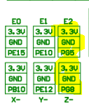
Then you would move your probe from Z- to E2 in this block on the SKR Pro board: